EP0860391A1 - Dispositif d'enroulement et procédé pour enrouler des bandes de papier ou similaire - Google Patents
Dispositif d'enroulement et procédé pour enrouler des bandes de papier ou similaire Download PDFInfo
- Publication number
- EP0860391A1 EP0860391A1 EP98660004A EP98660004A EP0860391A1 EP 0860391 A1 EP0860391 A1 EP 0860391A1 EP 98660004 A EP98660004 A EP 98660004A EP 98660004 A EP98660004 A EP 98660004A EP 0860391 A1 EP0860391 A1 EP 0860391A1
- Authority
- EP
- European Patent Office
- Prior art keywords
- reel
- reeling
- belt rolls
- belts
- equivalent
- Prior art date
- Legal status (The legal status is an assumption and is not a legal conclusion. Google has not performed a legal analysis and makes no representation as to the accuracy of the status listed.)
- Granted
Links
Images


Classifications
-
- B—PERFORMING OPERATIONS; TRANSPORTING
- B65—CONVEYING; PACKING; STORING; HANDLING THIN OR FILAMENTARY MATERIAL
- B65H—HANDLING THIN OR FILAMENTARY MATERIAL, e.g. SHEETS, WEBS, CABLES
- B65H18/00—Winding webs
-
- B—PERFORMING OPERATIONS; TRANSPORTING
- B65—CONVEYING; PACKING; STORING; HANDLING THIN OR FILAMENTARY MATERIAL
- B65H—HANDLING THIN OR FILAMENTARY MATERIAL, e.g. SHEETS, WEBS, CABLES
- B65H18/00—Winding webs
- B65H18/08—Web-winding mechanisms
- B65H18/26—Mechanisms for controlling contact pressure on winding-web package, e.g. for regulating the quantity of air between web layers
-
- B—PERFORMING OPERATIONS; TRANSPORTING
- B65—CONVEYING; PACKING; STORING; HANDLING THIN OR FILAMENTARY MATERIAL
- B65H—HANDLING THIN OR FILAMENTARY MATERIAL, e.g. SHEETS, WEBS, CABLES
- B65H18/00—Winding webs
- B65H18/08—Web-winding mechanisms
- B65H18/10—Mechanisms in which power is applied to web-roll spindle
-
- B—PERFORMING OPERATIONS; TRANSPORTING
- B65—CONVEYING; PACKING; STORING; HANDLING THIN OR FILAMENTARY MATERIAL
- B65H—HANDLING THIN OR FILAMENTARY MATERIAL, e.g. SHEETS, WEBS, CABLES
- B65H18/00—Winding webs
- B65H18/08—Web-winding mechanisms
- B65H18/14—Mechanisms in which power is applied to web roll, e.g. to effect continuous advancement of web
- B65H18/22—Mechanisms in which power is applied to web roll, e.g. to effect continuous advancement of web by friction band
-
- B—PERFORMING OPERATIONS; TRANSPORTING
- B65—CONVEYING; PACKING; STORING; HANDLING THIN OR FILAMENTARY MATERIAL
- B65H—HANDLING THIN OR FILAMENTARY MATERIAL, e.g. SHEETS, WEBS, CABLES
- B65H2301/00—Handling processes for sheets or webs
- B65H2301/40—Type of handling process
- B65H2301/41—Winding, unwinding
- B65H2301/414—Winding
- B65H2301/4146—Winding involving particular drive arrangement
- B65H2301/41466—Winding involving particular drive arrangement combinations of drives
Definitions
- the invention concerns a reeling device in accordance with the preamble of claim 1.
- the invention also concerns a method in accordance with the preamble of claim 13 in reeling of a paper web or equivalent.
- a traditional reel-up is based on loading of a reel drum and of a paper reel formed onto said reel drum against a reeling cylinder, and the construction of a prior-art reel-up is often complicated, and the reeling result achieved by means of said reel-up is also often inadequate.
- one of the factors for selecting the control has been the web tension that affects the quality of reeling, and in some prior-art solutions centre drive of the reel drum has also been employed in order to compensate for the linear load and for loads disadvantageous for the structure of the reel, which loads have mainly arisen from the mass of the reel increasing along with the progress of reeling.
- the present-day unwind stands are typically based on utilization of a centre drive coupled with the reel drum.
- the reel At the beginning of unwinding, the reel is accelerated by means of the centre drive, and at the running speed the drive performs a slight braking in order to maintain and to regulate the web tension.
- Problems of regulation are caused by the large mass of the roll and by possible non-roundness.
- the reel is supported on the reeling rails from the bearing housings of the reel drum only, which causes a disadvantageous loading in particular of the bottom layers of the reel, which arises from bending of the reel drum and from the mass of the reel and which increases the risk of formation of bottom broke.
- An increased diameter of the paper reel that is formed by means of the reel-up increases the efficiency of the reel-up and of the whole line of paper manufacture, provided that the loads that are produced by the increased reel mass and that are unfavourable for the structure of the reel can be controlled and kept at a sufficiently low level.
- the running of the process can be affected in a positive way if the control of the nip load can be influenced in an efficient way. Controlling of these loads is one of the most important objectives of the present invention.
- the reeling device in accordance with the invention is mainly characterized in what is stated in the characterizing part of claim 1.
- the controllability of the reeling nip is improved.
- belt support of the paper reel that is being formed which support is achieved by means of a set of belt rolls
- the nip pressures in the reeling nip remain considerably lower than with traditional reel-ups, because the nip is considerably longer and a belt as a material is softer than a reeling cylinder made of cast iron, in which case the loading profile of the nip effect is more even.
- the set of belt rolls is preferably composed of several separately adjustable parts, it is possible to utilize profiling of the nip load in the cross direction when the parts of the set of rolls are arranged so that they can be loaded independently.
- the belts that are used in the set of belt rolls are such that a sufficient/suitable friction between the belt and the web can be achieved.
- the belts can be both permeable or impermeable to air. In the set of belts, it is also possible to use both belt sorts as appropriately distributed.
- the reel drum is supported on rails and/or on a set of belt rolls so that the desired nip force is produced.
- the distribution of loading can vary within the range 0...100 %.
- the belt support in accordance with the invention is utilized in unwinding of a reel.
- the belt support may operate independently or together with centre drive.
- a support of the reel across the entire width and an extended nip of good hold qualities provided by the set of belts are achieved.
- the outlet angle of the web unwound from the reel can be made invariable, and thereby it is possible to attenuate variations of web tension arising, e.g., from non-roundness of the reel.
- the set of belts is preferably mounted so that, as viewed in the machine direction, its first end is stationary and the second end is displaceable in relation to the first end.
- a hydraulic cylinder or an equivalent actuator is used for regulation of the height of the second end.
- the loading of the set of belts can be controlled, for example, by means of a feedback of force or in compliance with measurement of the location of the set of belts by means of position regulation.
- the reeling device comprises measurement and/or control and/or storage members, which record and/or store information concerning the reeling process.
- Said information can be, among other things, information on the belt tension / on control of same, on a relief force / on control of same, on the mass of the reel and/or on non-roundness of the reel, on the position of the reeling carriages.
- the belt tension and the relief force are to be understood as a separate information/control related to a single unit of a set of belt rolls, a number of such units being possibly fitted in the cross direction of the web.
- the measurement data can also be some other reeling parameter.
- the measurement data can be used for controlling the reeling process during reeling, but the measurement data can also be transmitted further to other stages of the process as a control parameter.
- the data can also be stored specifically for each reel, in which case, for example, in unwinding it is possible to utilize the individual reel-up data of each machine reel, for example, in connection with its unwinding. In this way, favourably, in unwinding it is possible to take into account the cross-direction profile of the reel as a function of the reel diameter in unwinding, for example, by loading and/or relieving the reel by means of the set of belts so that the loading and/or the relief profile corresponds to that used in reeling up.
- a single set of belt rolls consists of one or several belts, in which case the operation of the reel-up does not necessarily depend on a single belt.
- the set of rolls is mounted preferably at the rear end, i.e. at the end next to the dry end, on the frame of the reel-up, and at the forward end there is a hydraulic cylinder or an equivalent actuator, by whose means the set of rolls can, among other things, be raised and lowered for passing a reel drum.
- the actuator it is also possible to regulate the position of the set of belt rolls in the vertical direction and the loading/relieving in compliance with the stage of reeling.
- Substitution for a reeling cylinder by a set of belt rolls in accordance with the invention also permits bringing of the stock of reel drums to the level of the reeling rails, which lowers the number of parts in the reel-up, increases the rigidity of the reel-up, and simplifies the sequence of operation of the reel-up and makes said sequence quicker. At the same time, the risks related to falling down in connection with lowering of reel drums are eliminated.
- the construction of the reel-up in accordance with the invention readily also permits connecting of the reel-up to the end of a paper or coating machine or some other finishing machine based on a supported web draw. If necessary, in connection with a set of belt rolls in accordance with the invention, it is possible to provide an air doctor or equivalent to keep the belts clean and to prevent winding of the web around the set of belt rolls.
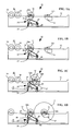
- Figures 1A...1D are schematic illustrations of a reel-up in accordance with the invention viewed in the longitudinal direction of the web in different stages of reeling,
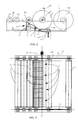
- Figure 2 is a schematic illustration of a second reel-up in accordance with the invention viewed in the longitudinal direction of the web
- FIG. 3 is a schematic illustration of a reel-up in accordance with the invention viewed from above
- Figure 4 is a schematic illustration of a mode in accordance with the invention for carrying out a reeling process in accordance with the invention
- FIG. 5 is a schematic illustration of the change process in a reeling device in accordance with the invention.
- Figure 6 is a schematic illustration of one mode in accordance with the invention for carrying out an unwind process in accordance with the invention.
- the paper web or equivalent is reeled into a paper reel 12 by means of the set of belt rolls 20 through the reeling nip N formed between the reel 12 that is formed and the set of belt rolls 20 onto the reel drum 31.
- the reel drum 31 is provided with centre drive 30a,30b.
- the reel drum 31 of the paper reel 12 is supported in the cross direction on reeling rails 13 or equivalent by means of reeling carriages 36,37 or equivalent.
- the reel-up 10 is in a stand-by stage.
- the reel drum 31 has been shifted to the reeling position, but the set of belt rolls 20 has not yet been raised to form the reeling nip N with the reel drum 31.
- the primary reeling sledge 36 has been fitted to support the reel drum 31, and the secondary reeling sledge 37 is still empty.
- the reel drum placed on the primary reeling sledge 36 can be coupled with the primary centre drive 30a, and the reel drum placed on the secondary reeling drum 37 can be coupled with the secondary centre drive 30b.
- the paper web or equivalent can be passed through the reeling nip N formed between the set of belt rolls 20 and the reel drum 31 to be reeled around the reel drum 31 into a paper reel.
- the reel 12 that is being completed is preferably in engagement with the secondary centre drive 30b and the new reel drum 31' in engagement with the primary centre drive 30a.
- a band change device or other solutions it is also possible to use a band change device or other solutions.
- the set of belt rolls 20 in accordance with the invention is provided with a tension regulation member 22, by whose means the nip pressure effective during reeling is regulated by regulating the tension of the belts 24.
- the set of belt rolls 20 is provided with a hydraulic cylinder 23 or with an equivalent actuator, by whose means the position of the set of belt rolls 20 in the direction of height can be regulated.
- the actuator 23 is connected to one end of the set of belt rolls 20, and the opposite end of the set of belt rolls is linked by means of an articulated joint 25 with the frame constructions or foundations of the reel-up 10.
- an air doctor 26 or equivalent is fitted, which keeps the belts 24 of the set of belt rolls clean and prevents winding of the web around the set of belt rolls 20.
- a second set of belt rolls 40 has been fitted.
- functions of its own can be assigned to each of the sets of belt rolls 20,40, for example, in relation to binding the surface of the web, initial acceleration, slowing down the complete machine reel, etc.
- two reeling nips N 2 and N 3 are produced at the same time for the same paper reel 12.
- the reel-up 10 is illustrated in a reeling situation substantially corresponding to Fig. 1D.
- the set of belt rolls 40 has been attached to the frame constructions or foundations of the reel-up 10, and it may comprise one or several belts in the cross direction of the web.
- a tension regulation member 42 for regulation of the tension of the belts, there is a tension regulation member 42.
- the set of belt rolls 40 can, if necessary, also be different from the set of rolls 20, for example provided with no actuator 23.
- the set of belt rolls 40 can also be provided with a drive.
- a blow device 38 is also shown, which will be described in more detail in relation to Fig. 5. This set of belts can also be provided with a doctor or equivalent.
- the set of belt rolls 20 is preferably composed of a number of modules 21 in the cross direction, in which case, either between the modules 21 or in place of a single belt 24 or at or below such a belt, it is possible to install a stationary lower blow pipe 38, by whose means the reel change and threading are carried out, preferably as of full width. If necessary, there may also be several pipes in the cross direction of the web.
- the medium that is blown is air, water or an adhesive or solid matter. An advantage of water is the effect of binding the surface sheets on a complete paper reel, in which case a rider device is not necessarily needed.
- a favourable change process in accordance with the invention is illustrated.
- the change can be carried out in a way in itself known, but preferably so that, by means of a blow pipe or equivalent 38 placed in connection with the set of belt rolls (herein just one pipe is shown, but there may also be several pipes in the cross direction), the web is cut off and/or a cut-off web is guided to around the new reel drum 31' and further into the nip N.
- the reel 12 that is being completed has been transferred into a position which permits the introduction of the new reel drum 31' into nip connection with the set of belt rolls 20.
- the new reel drum 31' has been accelerated to the web speed before it is brought into contact with the web.
- the change process is carried out preferably so that, at least substantially directly after the change, the initial reeling is carried out preferably against the roll R of the set of belts for a certain period of time.
- the blowing is carried out preferably so that the end W' of the cut-off web substantially maintains its speed and is guided in the direction of the face of the reel drum 31'.
- the change can also be carried out when the reel drum 31' forms a nip with the set of belts only, in which case the change blowing can be directed even more closely into the nip between the reel 31' and the set of belts substantially almost in the direction of the tangent of the roll.
- the blow pipe communicates with a source of blow medium through suitable ducts.
- each of the modules 21 in the set of belt rolls 20 comprises a number of belts 24, whose tension can be regulated either individually or jointly by means of the belt tension regulator 22.
- the belts used in the set of belt rolls 20 can be permeable 24' to air or impermeable 24.
- belts impermeable to air have been shown in the middle area of the set of belts, this is by no means supposed to confine the locations of the belts permeable and impermeable to air to that illustrated in the figure, but the illustration is just understood as an example. Under these circumstances, the properties of the belts in the set of belts and the positions of said belts in the cross direction are chosen in the way in compliance with the requirements imposed in each particular case.
- the primary reeling sledge 36 is placed at the front (in the wet end), and the secondary reeling sledge 37 is placed at the rear (in the dry end).
- a reel drum 34 is brought to the stock 35 and the holders are lowered and the reel drum 34 is passed to the stop position in the stock 35.
- the locking jaws of the primary reeling sledge 36 are closed, and the coupling of the primary-reel centre drive 30a is closed.
- the set of belt rolls 20 is lowered, and the primary reeling carriage 36 is passed to the reel-start position, Fig. 1A.
- the set of belt rolls 20 is raised, arrow S in Fig. 1B, by means of the hydraulic cylinder/cylinders 23 or an equivalent actuator(s), and a joint starting of the drives 30a and 25 is carried out (can also be started separately before the set of belt rolls 20 is raised).
- the web is widened to full width. If desired, a change blowing is blown, and initial reeling is carried out.
- the rear jaw of the secondary reeling sledge 37 is opened and the complete reel is delivered, after which the centre drive 30b is switched to running when the diameter of the reel is suitable.
- the secondary reeling sledge 37 is switched to loading, and the front jaw of the reeling sledge is raised (change of linear load).
- the coupling of the secondary centre drive 30b is closed (change of torque), and the coupling of the primary-reel centre drive 30a and the locking jaws of the primary-reel carriage are opened, and the primary-reel carriage 36 is shifted to the front to fetch an empty reel drum.
- the primary centre drive 30a is fitted at the tending side of the reeling device 10, and the secondary centre drive 30b at the driving side.
- a reel drum 34 is brought to the stock 35 if there is no drum as yet, and the holders are lowered, and the reel drum 34 is passed to the stop position in the stock 35.
- the reel drum 31 of the reel 12 that is being completed is in connection with the secondary reeling sledge 37, and the secondary centre drive 30b is in engagement, and the primary reeling sledge 36 is free to receive a new reel drum 31'.
- the locking jaws of the primary reeling carriage 36 and the coupling of the primary-reel centre drive 30a are closed early enough, and the primary-reel centre drive 30a is switched to running.
- the set of belt rolls 20 is lowered by means of the actuator 23, and the primary-reel carriage is shifted to the reel start position.
- the reel that is being completed is preferably all the time in nip contact with the set of belts.
- the set of belt rolls 20 is raised by means of the actuator 23, when the speeds are synchronized, the nip is closed and the change blowing is blown.
- the full reel is stopped, for example, with the aid of the centre drive under control while, for example, the set of belts 40 shown in Fig. 2 supports the reel.
- the secondary reeling sledge 37 can be shifted to the new reel that is being completed.
- the rear jaw of the secondary reeling sledge is raised, and the centre drive 30b is switched to running, and the secondary reeling sledge is switched to loading.
- the front jaw of the secondary reeling sledge is raised (change of linear load), and the coupling of the centre drive 30b is closed (change of torque).
- the coupling of the primary-reel centre drive 30a is opened, the locking jaws of the primary reeling carriage are opened, the primary reeling carriage is run to the front, etc.
- Fig. 4 shows a preferred embodiment of the invention, in which the reeling device in accordance with the invention comprises measurement and/or control and/or storage members 44, which record and/or store information on the reeling process.
- the information can be, among other things, information on the belt tension / on control of same A, on the relief force / control of same B, on the reel mass C, on the position of the reeling carriage D. Information can also be collected concerning other reeling parameters.
- the belt tension A and the relief force B should be understood as separate data/control for a single unit of set of belt rolls, a number of such units being possibly provided in the cross direction of the web.
- the measurement data can be used for controlling the reeling process during the reeling, but the measurement data can also be transmitted further to other stages of the process as a control parameter.
- the data can also be stored specifically for each reel, in which case, for example, in unwinding it is possible to make use of the measurement data.
- unwinding the cross-direction profile of the reel as a function of the reel diameter can be taken into account, for example, by loading and/or relieving the roll so that the loading/relief profile corresponds to that used in the reeling up.
- Fig. 6 is a schematic illustration of a mode in accordance with the invention for carrying out the unwind process in accordance with the invention. It comprises elements corresponding to those in a reel-up.
- the unwind stand 10b the paper web W or equivalent is unwound from a machine reel 12f by means of, and supported by, a set of belt rolls 20 through an unwind nip N formed between the reel 12f and the set of belt rolls 20 to be fed further into a process of treatment of the paper or equivalent, such as calendering or coating (not shown).
- a process of treatment of the paper or equivalent such as calendering or coating (not shown).
- the machine reel storage space 35 of the unwind stand 10b there are machine reels 12e in the waiting position.
- the reel drum 31" of the machine reel is provided with a centre drive 30c.
- the reel drum 31" of the paper reel 12f is supported in the cross direction on reeling rails 13 or equivalent by means of reeling carriages (not shown) or equivalent.
- the properties of the invention can be utilized substantially similarly to the reeling up described above.
Landscapes
- Replacement Of Web Rolls (AREA)
- Winding Of Webs (AREA)
- Machines For Manufacturing Corrugated Board In Mechanical Paper-Making Processes (AREA)
- Sanitary Thin Papers (AREA)
- Paper (AREA)
Applications Claiming Priority (2)
| Application Number | Priority Date | Filing Date | Title |
|---|---|---|---|
| FI970610 | 1997-02-13 | ||
| FI970610A FI106248B (fi) | 1997-02-13 | 1997-02-13 | Kiinnirullain ja menetelmä paperirainan tai vastaavan kiinnirullauksessa |
Publications (2)
| Publication Number | Publication Date |
|---|---|
| EP0860391A1 true EP0860391A1 (fr) | 1998-08-26 |
| EP0860391B1 EP0860391B1 (fr) | 2003-03-19 |
Family
ID=8548193
Family Applications (1)
| Application Number | Title | Priority Date | Filing Date |
|---|---|---|---|
| EP98660004A Expired - Lifetime EP0860391B1 (fr) | 1997-02-13 | 1998-01-28 | Dispositif d'enroulement et procédé pour enrouler des bandes de papier ou similaire |
Country Status (9)
| Country | Link |
|---|---|
| US (1) | US5918830A (fr) |
| EP (1) | EP0860391B1 (fr) |
| JP (1) | JPH10218443A (fr) |
| KR (1) | KR19980071352A (fr) |
| CN (1) | CN1093494C (fr) |
| AT (1) | ATE234784T1 (fr) |
| CA (1) | CA2229431C (fr) |
| DE (1) | DE69812196T2 (fr) |
| FI (1) | FI106248B (fr) |
Cited By (14)
| Publication number | Priority date | Publication date | Assignee | Title |
|---|---|---|---|---|
| EP1089931B1 (fr) * | 1998-06-10 | 2003-03-19 | The Goodyear Tire & Rubber Company | Enroulement de surface sur un enrouleur a structure en a |
| US6536702B1 (en) | 1998-06-10 | 2003-03-25 | The Goodyear Tire And Rubber Company | Surface winding on an a-frame winder |
| US6739544B2 (en) | 2001-03-29 | 2004-05-25 | Sumitomo Heavy Industries, Ltd. | Winding roll presser device and long material winding method |
| WO2004110909A1 (fr) * | 2003-06-17 | 2004-12-23 | Metso Paper, Inc. | Procede de rebobinage et bobine |
| WO2005026030A1 (fr) * | 2003-09-15 | 2005-03-24 | Metso Paper, Inc. | Bobineuse et procede associe |
| WO2005056446A1 (fr) * | 2003-12-15 | 2005-06-23 | Metso Paper, Inc | Procede et dispositif permettant de guider une bande |
| WO2005077796A2 (fr) * | 2004-02-12 | 2005-08-25 | Metso Paper, Inc. | Procede de bobinage et enrouleuse |
| WO2006003258A2 (fr) | 2004-06-30 | 2006-01-12 | Metso Paper, Inc | Procede dans une enrouleuse et enrouleuse |
| WO2006005804A1 (fr) * | 2004-06-30 | 2006-01-19 | Metso Paper, Inc | Procede et appareil de reglage du profil d'espacement d'un espacement d'enroulement |
| WO2006041385A1 (fr) * | 2004-10-11 | 2006-04-20 | Metso Paper, Inc. | Bobineuse et procede et unite de mesure presents dans une telle bobineuse |
| WO2007026324A1 (fr) * | 2005-08-31 | 2007-03-08 | The Procter & Gamble Company | Enrouleur hybride |
| EP1761448A1 (fr) * | 2004-07-01 | 2007-03-14 | Metso Paper, Inc. | Procede et systeme d'enroulement et appareil de mesure |
| DE102011085141A1 (de) | 2010-10-25 | 2012-04-26 | Metso Paper, Inc. | Verfahren beim Aufwickeln in einer Faserbahnmaschine und ein Aufwickelkonzept |
| IT201800009199A1 (it) * | 2018-10-05 | 2020-04-05 | Tecno Paper Srl | Ribobinatrice da cartiera con dispositivo di cambio bobina in continuo |
Families Citing this family (31)
| Publication number | Priority date | Publication date | Assignee | Title |
|---|---|---|---|---|
| FI112678B (fi) * | 2001-08-22 | 2003-12-31 | Metso Paper Inc | Menetelmä ja laitteisto päänvientinauhan viemiseksi vapaavälin yli |
| FI106248B (fi) * | 1997-02-13 | 2000-12-29 | Valmet Corp | Kiinnirullain ja menetelmä paperirainan tai vastaavan kiinnirullauksessa |
| FI108429B (fi) * | 1997-12-22 | 2002-01-31 | Metso Paper Inc | Painotelarullain |
| FI104161B1 (fi) * | 1998-02-17 | 1999-11-30 | Valmet Corp | Menetelmä ja laitteisto rainan rullauksessa |
| FI105467B (fi) * | 1998-10-16 | 2000-08-31 | Valmet Corp | Menetelmä konerullan pysäyttämiseksi |
| US6427938B1 (en) * | 1998-10-22 | 2002-08-06 | Voith Sulzer Papiertechnik Patent Gmbh | Process and apparatus for cutting a running material web |
| DE19848815A1 (de) * | 1998-10-22 | 2000-04-27 | Voith Sulzer Papiertech Patent | Wickelmaschine |
| US6749723B2 (en) * | 2000-06-28 | 2004-06-15 | Metso Paper Karlstad Ab | Measuring arrangements in a shortened dry end of a tissue machine |
| US6669818B2 (en) | 2000-06-28 | 2003-12-30 | Metso Paper Karlstad Ab | Shortened layout from dryer to reel in tissue machine |
| US6729572B2 (en) * | 2001-10-31 | 2004-05-04 | Kimberly-Clark Worldwide, Inc. | Mandrelless center/surface rewinder and winder |
| US7001487B2 (en) * | 2001-12-19 | 2006-02-21 | Kimberly-Clark Worldwide, Inc. | Method and apparatus for transporting a sheet from a dryer to a reel |
| US8042761B2 (en) * | 2002-02-28 | 2011-10-25 | Kimberly-Clark Worldwide, Inc. | Center/surface rewinder and winder |
| US8757533B2 (en) * | 2002-02-28 | 2014-06-24 | Kimberly-Clark Worldwide, Inc. | Center/surface rewinder and winder |
| US8210462B2 (en) | 2002-02-28 | 2012-07-03 | Kimberly-Clark Worldwide, Inc. | Center/surface rewinder and winder |
| US7909282B2 (en) * | 2002-02-28 | 2011-03-22 | Kimberly-Clark Worldwide, Inc. | Center/surface rewinder and winder |
| DE102004051235A1 (de) * | 2004-10-20 | 2006-05-04 | Albrecht Bäumer GmbH & Co.KG Spezialmaschinenfabrik | Wicklereinheit |
| FI121229B (fi) * | 2005-07-08 | 2010-08-31 | Metso Paper Inc | Menetelmä hihnarullaimessa ja hihnarullain |
| US7661622B2 (en) | 2005-09-30 | 2010-02-16 | Kimberly-Clark Worldwide, Inc. | Apparatus and method for winding and transporting paper |
| FI120443B (fi) | 2006-02-02 | 2009-10-30 | Metso Paper Inc | Menetelmä kuiturainakoneen kiinnirullaimen yhteydessä |
| US7789338B2 (en) * | 2006-02-27 | 2010-09-07 | A. Celli Nonwovens S.P.A. | Winding rod for winding reels of weblike material, and machine that uses said rod |
| FI120729B (fi) * | 2008-07-31 | 2010-02-15 | Metso Paper Inc | Kuiturainan valmistuslinja ja menetelmä |
| US8535780B2 (en) | 2009-10-06 | 2013-09-17 | Kimberly-Clark Worldwide, Inc. | Coreless tissue rolls and method of making the same |
| US8714472B2 (en) | 2010-03-30 | 2014-05-06 | Kimberly-Clark Worldwide, Inc. | Winder registration and inspection system |
| US8364290B2 (en) | 2010-03-30 | 2013-01-29 | Kimberly-Clark Worldwide, Inc. | Asynchronous control of machine motion |
| ES2393006B1 (es) | 2011-06-01 | 2013-12-12 | Comexi Group Industries Sau | Bobinadora tipo revolver para material en banda. |
| CN103569707A (zh) * | 2013-10-18 | 2014-02-12 | 安徽华印机电股份有限公司 | 一种除尘复卷装置 |
| CN104772994B (zh) * | 2014-01-09 | 2018-01-19 | 精工爱普生株式会社 | 卷筒纸输送控制方法、卷筒纸输送装置以及打印机 |
| US9352921B2 (en) | 2014-03-26 | 2016-05-31 | Kimberly-Clark Worldwide, Inc. | Method and apparatus for applying adhesive to a moving web being wound into a roll |
| KR20160029562A (ko) | 2014-09-05 | 2016-03-15 | 남강제지주식회사 | 코팅된 제지용 권취 장치 |
| CN105034549B (zh) * | 2015-08-24 | 2018-09-18 | 福建东南艺术纸品股份有限公司 | 一种进纸机构改进的柔印机 |
| JP7006938B2 (ja) * | 2018-12-21 | 2022-01-24 | 株式会社ミヤコシ | 連続ラベル用紙の抜き粕巻取り装置 |
Citations (4)
| Publication number | Priority date | Publication date | Assignee | Title |
|---|---|---|---|---|
| US4283023A (en) * | 1978-03-22 | 1981-08-11 | Escher Wyss Gmbh | Winder apparatus for a paper machine |
| US4830304A (en) * | 1987-01-26 | 1989-05-16 | Kabushiki Kaisha Kaneda Kikai Seisakusho | Automatic device for treating unusable paper used in device for preparing rolls for web pasting |
| US5150850A (en) * | 1991-05-10 | 1992-09-29 | Beloit Corporation | Method for winding a traveling web on a belted two drum wound web roll winder |
| US5393008A (en) * | 1991-09-18 | 1995-02-28 | Valmet-Karlstad | Reel-up with separately acting actuators for influencing linear pressure |
Family Cites Families (17)
| Publication number | Priority date | Publication date | Assignee | Title |
|---|---|---|---|---|
| US3098619A (en) * | 1960-12-23 | 1963-07-23 | Beloit Iron Works | Winder drum arrangement |
| US3471097A (en) * | 1967-11-06 | 1969-10-07 | Black Clawson Co | Method and apparatus for stopping the rotation of a fully wound roll of web material |
| US3698658A (en) * | 1969-11-25 | 1972-10-17 | Inge Skei | Recording apparatus for sonar and echo sounding systems |
| US3687388A (en) * | 1969-12-12 | 1972-08-29 | Beloit Corp | Measuring and controlling wound-in tension for web winding machines |
| US4034928A (en) * | 1976-06-29 | 1977-07-12 | Union Carbide Corporation | Method and apparatus for producing coreless roll assemblies of separable bags |
| AT355417B (de) * | 1977-04-26 | 1980-03-10 | Escher Wyss Gmbh | Wickelvorrichtung fuer papiermaschinen |
| IT1100423B (it) * | 1978-11-29 | 1985-09-28 | Alberto Pietro | Macchina automatica per la realizzazione in continuo di rotoli di tessuto |
| AT379566B (de) * | 1982-12-22 | 1986-01-27 | Fehrer Textilmasch | Vorrichtung zum abwickeln von vliesrollen |
| FI74260C (fi) * | 1985-11-20 | 1988-01-11 | Valmet Paper Machinery Inc | Upprullningsanordning. |
| JPS6376751U (fr) * | 1986-11-04 | 1988-05-21 | ||
| US5058820A (en) * | 1987-01-30 | 1991-10-22 | Canon Kabushiki Kaisha | Strip-like member take-up device |
| FI81768C (fi) * | 1987-05-20 | 1990-12-10 | Valmet Paper Machinery Inc | Foerfarande och anordning vid rullning av papper. |
| FI81770C (fi) * | 1987-05-20 | 1990-12-10 | Valmet Paper Machinery Inc | Foerfarande vid styrning av pappers rullstol. |
| IT1247127B (it) * | 1991-03-04 | 1994-12-12 | Colines Srl | Apparecchio di avvolgimento per nastro di materiale a foglio |
| FI94231C (fi) * | 1993-12-16 | 1995-08-10 | Valmet Paper Machinery Inc | Menetelmä ja laite paperi- tai kartonkirainan kiinnirullauksessa pope-rullaimessa tai vastaavassa |
| FI99278C (fi) * | 1996-06-10 | 1998-04-27 | Valmet Corp | Säätömenetelmä rullauksessa |
| FI106248B (fi) * | 1997-02-13 | 2000-12-29 | Valmet Corp | Kiinnirullain ja menetelmä paperirainan tai vastaavan kiinnirullauksessa |
-
1997
- 1997-02-13 FI FI970610A patent/FI106248B/fi not_active IP Right Cessation
-
1998
- 1998-01-28 EP EP98660004A patent/EP0860391B1/fr not_active Expired - Lifetime
- 1998-01-28 DE DE69812196T patent/DE69812196T2/de not_active Expired - Lifetime
- 1998-01-28 AT AT98660004T patent/ATE234784T1/de active
- 1998-02-12 CN CN98103737A patent/CN1093494C/zh not_active Expired - Fee Related
- 1998-02-13 KR KR1019980004427A patent/KR19980071352A/ko not_active Application Discontinuation
- 1998-02-13 CA CA002229431A patent/CA2229431C/fr not_active Expired - Fee Related
- 1998-02-13 JP JP10046372A patent/JPH10218443A/ja active Pending
- 1998-02-13 US US09/023,988 patent/US5918830A/en not_active Expired - Lifetime
Patent Citations (4)
| Publication number | Priority date | Publication date | Assignee | Title |
|---|---|---|---|---|
| US4283023A (en) * | 1978-03-22 | 1981-08-11 | Escher Wyss Gmbh | Winder apparatus for a paper machine |
| US4830304A (en) * | 1987-01-26 | 1989-05-16 | Kabushiki Kaisha Kaneda Kikai Seisakusho | Automatic device for treating unusable paper used in device for preparing rolls for web pasting |
| US5150850A (en) * | 1991-05-10 | 1992-09-29 | Beloit Corporation | Method for winding a traveling web on a belted two drum wound web roll winder |
| US5393008A (en) * | 1991-09-18 | 1995-02-28 | Valmet-Karlstad | Reel-up with separately acting actuators for influencing linear pressure |
Cited By (23)
| Publication number | Priority date | Publication date | Assignee | Title |
|---|---|---|---|---|
| EP1089931B1 (fr) * | 1998-06-10 | 2003-03-19 | The Goodyear Tire & Rubber Company | Enroulement de surface sur un enrouleur a structure en a |
| US6536702B1 (en) | 1998-06-10 | 2003-03-25 | The Goodyear Tire And Rubber Company | Surface winding on an a-frame winder |
| US6739544B2 (en) | 2001-03-29 | 2004-05-25 | Sumitomo Heavy Industries, Ltd. | Winding roll presser device and long material winding method |
| DE10213841B4 (de) * | 2001-03-29 | 2008-11-27 | Sumitomo Heavy Industries, Ltd. | Wickelrollenanpressvorrichtung zum Aufwickeln von langen Materialien |
| WO2004110909A1 (fr) * | 2003-06-17 | 2004-12-23 | Metso Paper, Inc. | Procede de rebobinage et bobine |
| WO2005026030A1 (fr) * | 2003-09-15 | 2005-03-24 | Metso Paper, Inc. | Bobineuse et procede associe |
| WO2005056446A1 (fr) * | 2003-12-15 | 2005-06-23 | Metso Paper, Inc | Procede et dispositif permettant de guider une bande |
| WO2005077796A2 (fr) * | 2004-02-12 | 2005-08-25 | Metso Paper, Inc. | Procede de bobinage et enrouleuse |
| WO2005077796A3 (fr) * | 2004-02-12 | 2005-10-06 | Metso Paper Inc | Procede de bobinage et enrouleuse |
| WO2006003258A3 (fr) * | 2004-06-30 | 2006-04-13 | Metso Paper Inc | Procede dans une enrouleuse et enrouleuse |
| WO2006003258A2 (fr) | 2004-06-30 | 2006-01-12 | Metso Paper, Inc | Procede dans une enrouleuse et enrouleuse |
| EP2256074A1 (fr) | 2004-06-30 | 2010-12-01 | Metso Paper Inc. | Procédé dans une enrouleuse et enrouleuse |
| US7832677B2 (en) | 2004-06-30 | 2010-11-16 | Metso Paper, Inc. | Method and an apparatus for controlling a nip profile of a reeling nip |
| WO2006005804A1 (fr) * | 2004-06-30 | 2006-01-19 | Metso Paper, Inc | Procede et appareil de reglage du profil d'espacement d'un espacement d'enroulement |
| EP1761448A1 (fr) * | 2004-07-01 | 2007-03-14 | Metso Paper, Inc. | Procede et systeme d'enroulement et appareil de mesure |
| EP1761448A4 (fr) * | 2004-07-01 | 2013-11-06 | Metso Paper Inc | Procede et systeme d'enroulement et appareil de mesure |
| WO2006041385A1 (fr) * | 2004-10-11 | 2006-04-20 | Metso Paper, Inc. | Bobineuse et procede et unite de mesure presents dans une telle bobineuse |
| US7845592B2 (en) | 2004-10-11 | 2010-12-07 | Metso Paper, Inc. | Reel-up and also a method and measuring unit in such a reel-up |
| WO2007026324A1 (fr) * | 2005-08-31 | 2007-03-08 | The Procter & Gamble Company | Enrouleur hybride |
| DE102011085141A1 (de) | 2010-10-25 | 2012-04-26 | Metso Paper, Inc. | Verfahren beim Aufwickeln in einer Faserbahnmaschine und ein Aufwickelkonzept |
| IT201800009199A1 (it) * | 2018-10-05 | 2020-04-05 | Tecno Paper Srl | Ribobinatrice da cartiera con dispositivo di cambio bobina in continuo |
| WO2020070765A1 (fr) * | 2018-10-05 | 2020-04-09 | Tecno Paper Srl | Rebobineuse de papeterie avec dispositif de changement de bobine en continu |
| US11866278B2 (en) | 2018-10-05 | 2024-01-09 | Tecno Paper Srl | Paper mill rewinder with continuous reel change device |
Also Published As
| Publication number | Publication date |
|---|---|
| DE69812196T2 (de) | 2003-10-23 |
| ATE234784T1 (de) | 2003-04-15 |
| EP0860391B1 (fr) | 2003-03-19 |
| CA2229431A1 (fr) | 1998-08-13 |
| FI970610A0 (fi) | 1997-02-13 |
| FI970610A (fi) | 1998-08-14 |
| KR19980071352A (ko) | 1998-10-26 |
| CN1093494C (zh) | 2002-10-30 |
| CA2229431C (fr) | 2003-09-09 |
| US5918830A (en) | 1999-07-06 |
| FI106248B (fi) | 2000-12-29 |
| CN1190638A (zh) | 1998-08-19 |
| JPH10218443A (ja) | 1998-08-18 |
| DE69812196D1 (de) | 2003-04-24 |
Similar Documents
| Publication | Publication Date | Title |
|---|---|---|
| EP0860391B1 (fr) | Dispositif d'enroulement et procédé pour enrouler des bandes de papier ou similaire | |
| KR100365120B1 (ko) | 드럼 릴-업(drum reel-up)등에 종이 및 판지웨브를 권취하는 방법 및 장치 | |
| US5560566A (en) | Winder with elevated spool support rail | |
| US6629659B1 (en) | Method and apparatus for measuring web tension profile to control the reeling of a web | |
| US6038789A (en) | Method for controlling the curl of paper and a paper or board machine line that applies the method | |
| JPH09124198A (ja) | 紙ウエブまたは板紙ウエブの巻取り方法および装置 | |
| EP1928770B1 (fr) | Appareil et methode pour enrouler et transporter du papier | |
| CA2054250C (fr) | Enrouleuse et methode de regulation de la pression au point de pincage dans une enrouleuse | |
| CA2328189A1 (fr) | Procede et appareil pour enrouler une bande de papier en mouvement | |
| JP2002518272A (ja) | ウェブの巻取機及び巻取方法 | |
| US6604703B2 (en) | Method and winder for continuous winding of a material web | |
| US20080029237A1 (en) | Wet/dry crepe swing paper machinery | |
| EP1285126B1 (fr) | Procede et dispositif de fabrication d'une bande de papier ou de carton dans lesquels le dispositif de finition peut etre derive | |
| FI120086B (fi) | Menetelmä rullauksessa ja kiinnirullain | |
| FI100003B (fi) | Sovitelma off-machine-paperinkäsittelylinjan aukirullaimen puoleisessa päässä |
Legal Events
| Date | Code | Title | Description |
|---|---|---|---|
| PUAI | Public reference made under article 153(3) epc to a published international application that has entered the european phase |
Free format text: ORIGINAL CODE: 0009012 |
|
| AK | Designated contracting states |
Kind code of ref document: A1 Designated state(s): AT DE FI FR GB IT SE |
|
| AX | Request for extension of the european patent |
Free format text: AL;LT;LV;MK;RO;SI |
|
| 17P | Request for examination filed |
Effective date: 19980813 |
|
| AKX | Designation fees paid |
Free format text: AT DE FI FR GB IT SE |
|
| RBV | Designated contracting states (corrected) |
Designated state(s): AT DE FI FR GB IT SE |
|
| 17Q | First examination report despatched |
Effective date: 20000817 |
|
| RAP1 | Party data changed (applicant data changed or rights of an application transferred) |
Owner name: VALMET CORPORATION(REG.NO.763281) |
|
| RAP1 | Party data changed (applicant data changed or rights of an application transferred) |
Owner name: METSO PAPER, INC. |
|
| RAP1 | Party data changed (applicant data changed or rights of an application transferred) |
Owner name: METSO PAPER, INC. |
|
| GRAH | Despatch of communication of intention to grant a patent |
Free format text: ORIGINAL CODE: EPIDOS IGRA |
|
| GRAH | Despatch of communication of intention to grant a patent |
Free format text: ORIGINAL CODE: EPIDOS IGRA |
|
| GRAA | (expected) grant |
Free format text: ORIGINAL CODE: 0009210 |
|
| AK | Designated contracting states |
Designated state(s): AT DE FI FR GB IT SE |
|
| PG25 | Lapsed in a contracting state [announced via postgrant information from national office to epo] |
Ref country code: FI Free format text: LAPSE BECAUSE OF FAILURE TO SUBMIT A TRANSLATION OF THE DESCRIPTION OR TO PAY THE FEE WITHIN THE PRESCRIBED TIME-LIMIT Effective date: 20030319 |
|
| REG | Reference to a national code |
Ref country code: GB Ref legal event code: FG4D |
|
| REF | Corresponds to: |
Ref document number: 69812196 Country of ref document: DE Date of ref document: 20030424 Kind code of ref document: P |
|
| REG | Reference to a national code |
Ref country code: SE Ref legal event code: TRGR |
|
| ET | Fr: translation filed | ||
| PLBE | No opposition filed within time limit |
Free format text: ORIGINAL CODE: 0009261 |
|
| STAA | Information on the status of an ep patent application or granted ep patent |
Free format text: STATUS: NO OPPOSITION FILED WITHIN TIME LIMIT |
|
| 26N | No opposition filed |
Effective date: 20031222 |
|
| GBPC | Gb: european patent ceased through non-payment of renewal fee |
Effective date: 20070128 |
|
| PG25 | Lapsed in a contracting state [announced via postgrant information from national office to epo] |
Ref country code: GB Free format text: LAPSE BECAUSE OF NON-PAYMENT OF DUE FEES Effective date: 20070128 |
|
| PGFP | Annual fee paid to national office [announced via postgrant information from national office to epo] |
Ref country code: GB Payment date: 20060120 Year of fee payment: 9 |
|
| PGFP | Annual fee paid to national office [announced via postgrant information from national office to epo] |
Ref country code: FR Payment date: 20120206 Year of fee payment: 15 |
|
| PGFP | Annual fee paid to national office [announced via postgrant information from national office to epo] |
Ref country code: SE Payment date: 20120120 Year of fee payment: 15 Ref country code: IT Payment date: 20120126 Year of fee payment: 15 |
|
| PGFP | Annual fee paid to national office [announced via postgrant information from national office to epo] |
Ref country code: DE Payment date: 20130122 Year of fee payment: 16 |
|
| PGFP | Annual fee paid to national office [announced via postgrant information from national office to epo] |
Ref country code: AT Payment date: 20130111 Year of fee payment: 16 |
|
| REG | Reference to a national code |
Ref country code: SE Ref legal event code: EUG |
|
| REG | Reference to a national code |
Ref country code: FR Ref legal event code: ST Effective date: 20130930 |
|
| PG25 | Lapsed in a contracting state [announced via postgrant information from national office to epo] |
Ref country code: SE Free format text: LAPSE BECAUSE OF NON-PAYMENT OF DUE FEES Effective date: 20130129 |
|
| PG25 | Lapsed in a contracting state [announced via postgrant information from national office to epo] |
Ref country code: FR Free format text: LAPSE BECAUSE OF NON-PAYMENT OF DUE FEES Effective date: 20130131 |
|
| REG | Reference to a national code |
Ref country code: DE Ref legal event code: R119 Ref document number: 69812196 Country of ref document: DE |
|
| REG | Reference to a national code |
Ref country code: AT Ref legal event code: MM01 Ref document number: 234784 Country of ref document: AT Kind code of ref document: T Effective date: 20140128 |
|
| REG | Reference to a national code |
Ref country code: DE Ref legal event code: R119 Ref document number: 69812196 Country of ref document: DE Effective date: 20140801 |
|
| PG25 | Lapsed in a contracting state [announced via postgrant information from national office to epo] |
Ref country code: DE Free format text: LAPSE BECAUSE OF NON-PAYMENT OF DUE FEES Effective date: 20140801 |
|
| PG25 | Lapsed in a contracting state [announced via postgrant information from national office to epo] |
Ref country code: AT Free format text: LAPSE BECAUSE OF NON-PAYMENT OF DUE FEES Effective date: 20140128 |
|
| PG25 | Lapsed in a contracting state [announced via postgrant information from national office to epo] |
Ref country code: IT Free format text: LAPSE BECAUSE OF NON-PAYMENT OF DUE FEES Effective date: 20140128 |