EP0859518B1 - Reduction of noise generated by a digital picture coder/decoder which operates in blocks - Google Patents
Reduction of noise generated by a digital picture coder/decoder which operates in blocks Download PDFInfo
- Publication number
- EP0859518B1 EP0859518B1 EP19980300812 EP98300812A EP0859518B1 EP 0859518 B1 EP0859518 B1 EP 0859518B1 EP 19980300812 EP19980300812 EP 19980300812 EP 98300812 A EP98300812 A EP 98300812A EP 0859518 B1 EP0859518 B1 EP 0859518B1
- Authority
- EP
- European Patent Office
- Prior art keywords
- picture
- noise
- signals
- block
- encoding
- Prior art date
- Legal status (The legal status is an assumption and is not a legal conclusion. Google has not performed a legal analysis and makes no representation as to the accuracy of the status listed.)
- Expired - Lifetime
Links
Images


Classifications
-
- H—ELECTRICITY
- H04—ELECTRIC COMMUNICATION TECHNIQUE
- H04N—PICTORIAL COMMUNICATION, e.g. TELEVISION
- H04N19/00—Methods or arrangements for coding, decoding, compressing or decompressing digital video signals
- H04N19/85—Methods or arrangements for coding, decoding, compressing or decompressing digital video signals using pre-processing or post-processing specially adapted for video compression
- H04N19/86—Methods or arrangements for coding, decoding, compressing or decompressing digital video signals using pre-processing or post-processing specially adapted for video compression involving reduction of coding artifacts, e.g. of blockiness
-
- H—ELECTRICITY
- H04—ELECTRIC COMMUNICATION TECHNIQUE
- H04N—PICTORIAL COMMUNICATION, e.g. TELEVISION
- H04N19/00—Methods or arrangements for coding, decoding, compressing or decompressing digital video signals
- H04N19/10—Methods or arrangements for coding, decoding, compressing or decompressing digital video signals using adaptive coding
- H04N19/102—Methods or arrangements for coding, decoding, compressing or decompressing digital video signals using adaptive coding characterised by the element, parameter or selection affected or controlled by the adaptive coding
- H04N19/117—Filters, e.g. for pre-processing or post-processing
-
- H—ELECTRICITY
- H04—ELECTRIC COMMUNICATION TECHNIQUE
- H04N—PICTORIAL COMMUNICATION, e.g. TELEVISION
- H04N19/00—Methods or arrangements for coding, decoding, compressing or decompressing digital video signals
- H04N19/10—Methods or arrangements for coding, decoding, compressing or decompressing digital video signals using adaptive coding
- H04N19/134—Methods or arrangements for coding, decoding, compressing or decompressing digital video signals using adaptive coding characterised by the element, parameter or criterion affecting or controlling the adaptive coding
- H04N19/136—Incoming video signal characteristics or properties
- H04N19/137—Motion inside a coding unit, e.g. average field, frame or block difference
-
- H—ELECTRICITY
- H04—ELECTRIC COMMUNICATION TECHNIQUE
- H04N—PICTORIAL COMMUNICATION, e.g. TELEVISION
- H04N19/00—Methods or arrangements for coding, decoding, compressing or decompressing digital video signals
- H04N19/10—Methods or arrangements for coding, decoding, compressing or decompressing digital video signals using adaptive coding
- H04N19/134—Methods or arrangements for coding, decoding, compressing or decompressing digital video signals using adaptive coding characterised by the element, parameter or criterion affecting or controlling the adaptive coding
- H04N19/136—Incoming video signal characteristics or properties
- H04N19/14—Coding unit complexity, e.g. amount of activity or edge presence estimation
-
- H—ELECTRICITY
- H04—ELECTRIC COMMUNICATION TECHNIQUE
- H04N—PICTORIAL COMMUNICATION, e.g. TELEVISION
- H04N19/00—Methods or arrangements for coding, decoding, compressing or decompressing digital video signals
- H04N19/10—Methods or arrangements for coding, decoding, compressing or decompressing digital video signals using adaptive coding
- H04N19/169—Methods or arrangements for coding, decoding, compressing or decompressing digital video signals using adaptive coding characterised by the coding unit, i.e. the structural portion or semantic portion of the video signal being the object or the subject of the adaptive coding
- H04N19/17—Methods or arrangements for coding, decoding, compressing or decompressing digital video signals using adaptive coding characterised by the coding unit, i.e. the structural portion or semantic portion of the video signal being the object or the subject of the adaptive coding the unit being an image region, e.g. an object
- H04N19/176—Methods or arrangements for coding, decoding, compressing or decompressing digital video signals using adaptive coding characterised by the coding unit, i.e. the structural portion or semantic portion of the video signal being the object or the subject of the adaptive coding the unit being an image region, e.g. an object the region being a block, e.g. a macroblock
-
- H—ELECTRICITY
- H04—ELECTRIC COMMUNICATION TECHNIQUE
- H04N—PICTORIAL COMMUNICATION, e.g. TELEVISION
- H04N19/00—Methods or arrangements for coding, decoding, compressing or decompressing digital video signals
- H04N19/50—Methods or arrangements for coding, decoding, compressing or decompressing digital video signals using predictive coding
- H04N19/503—Methods or arrangements for coding, decoding, compressing or decompressing digital video signals using predictive coding involving temporal prediction
- H04N19/51—Motion estimation or motion compensation
- H04N19/527—Global motion vector estimation
-
- H—ELECTRICITY
- H04—ELECTRIC COMMUNICATION TECHNIQUE
- H04N—PICTORIAL COMMUNICATION, e.g. TELEVISION
- H04N19/00—Methods or arrangements for coding, decoding, compressing or decompressing digital video signals
- H04N19/60—Methods or arrangements for coding, decoding, compressing or decompressing digital video signals using transform coding
- H04N19/61—Methods or arrangements for coding, decoding, compressing or decompressing digital video signals using transform coding in combination with predictive coding
Definitions
- This invention relates to picture signal processing methods and apparatus.
- block encoding such as block DCT (discrete cosine transform) encoding.
- block distortion (block noise) tends to be produced, such that, the higher the compression factor, the larger becomes the distortion.
- This block distortion is produced by the fact that DCT is executed in a closed space in a block without taking account of the correlation beyond the block boundary. Thus, continuity cannot be maintained in the block boundaries, so that the deviation in the playback data value at the boundary area to the neighboring blocks is perceived as noise.
- the block distortion, produced on block encoding picture data exhibits certain periodicity and hence is perceived more readily than the usual random noise so that it proves to be a significant factor in producing picture quality deterioration.
- the mosquito noise means a ringing output picture distortion produced by high frequency components in the quantization error.
- picture quality correction such as by contour enhancement
- picture quality correction is effected at the time of picture compression/expansion accompanying block encoding, the above-mentioned block distortion or mosquito noise is emphasized to render it difficult to improve the picture quality sufficiently.
- a so-called video CD player there is proposed a structure in which the noise is removed by a field recursive type noise filter, periodic signals are appended by a NTSC encoder, the resulting signal is converted by a D/A converter into analog signals and the resulting analog signals are processed by a contour enhancement circuit for improving the picture definition.
- the block distortion or the mosquito noise, not removed by a field recursive type noise reducer is also amplified by the contour enhancement circuit to render it difficult to achieve sufficient improvement in the picture quality.
- the present invention provides a picture signal processing apparatus according to claim 1 hereof and a picture signal processing method according to claim 6 hereof.
- Embodiments of the invention can provide a picture signal processing method and apparatus whereby reduction in the block distortion of the mosquito noise at the time of block encoding, such as DCT, and correction of the picture quality, such as contour enhancement, can be realized effectively.
- the decoded picture signals are reduced in noise and subsequently the noise-reduced picture signals are corrected for picture quality.
- picture quality correction such as contour enhancement
- the quantization distortion or noise such as block distortion or mosquito noise
- picture quality compansion such as block DCT encoding
- picture quality correction such as contour enhancement
- the noise in the frame of the picture quality is first reduced, and subsequently the noise generated between the frames is reduced, thus effectively removing the distortion occurring in a frame and the distortion or noise occurring between the frames.
- Fig.1 is a schematic block diagram showing a structure of a picture signal processing device according to the present invention.
- Fig.2 is a block diagram showing an illustrative structure of a noise reducing circuit according to the present invention.
- Figs. 3a to 3c illustrate decimation and interpolation in the structure of Fig. 2.
- Fig.4 is a schematic block diagram showing the structure of a picture data block distortion reducing circuit according to the present invention.
- Fig.5 shows pixels in the vicinity of a block boundary for correcting block distortion.
- Fig.6 shows an example of the relation between the quantization step as the encoding information and the threshold value for block distortion discrimination.
- Figs. 7a and 7b illustrate the operation of correcting the step difference in the block boundary.
- Fig.8 is a block diagram showing an example of a field recursive type noise reducing circuit.
- Fig.9 is a schematic block diagram showing the structure of an example of a contour enhancement circuit as picture quality correction means.
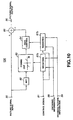
- Fig.10 is a block diagram showing another illustrative example of the contour enhancement circuit.
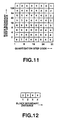
- Fig.11 shows typical quantization step weighting coefficients for the step difference in the block boundary and the quantization step code.
- Fig.12 shows an illustrative example of the boundary separation weighting coefficients for the block boundary separation.
- Fig. 13 shows coring weighting coefficients for the quantization step codes and the block boundary step difference.
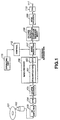
- Fig. 1 is a schematic block diagram showing a structure of an overall system in case a picture signal processing device according to the present invention is applied to a video CD player
- RF signals read from a disc 101 such as a video CD or a CD-ROM, by an optical pickup 102, are entered to a RF amplifier 103.
- the amplified RF signals are demodulated by an eight-to-fourteen (EFM) demodulation circuit 104 so as to enter a disc recording format decoder, such as a CD-ROM decoder 105, as serial data.
- EFM eight-to-fourteen
- the CD-ROM decoder 105 converts the serial data into, for example, a MPEG bitstream signal, which is sent to a MPEG decoder 106.
- MPEG is an abbreviation of Moving Picture Experts Group for compression encoding of moving pictures of ISO/IEC JTC1/SC29 (International Organization for Standardization/International Electrotechnical Commission, Joint Technical Committee 1/Sub-Committee 29.
- ISO11172 and IS013818 are standardized under an item of multimedia multiplexing
- IS011172-2 and IS013333818-2 are standardized under an item of video
- ISO11172-3 and ISO13818-3 are standardized under an item of audio.
- picture signals are compression-encoded on the picture basis (on the frame or field basis) by exploiting the temporal and spatial picture correlation.
- the block DCT encoding is used by way of exploiting the correlation in the spatial direction.
- decoding is carried out in accordance with the MPEG1 format.
- dequantization by a dequantizer 161 inverse DCT processing by an inverse DCT circuit 162 and interpolation or the like processing, if need be, are carried out in this order before outputting.
- the picture signals, outputted by the MPEG decoder 106, are entered to a block distortion reducing circuit 107 as a noise reducer. Since these signals contain the block distortion due to compansion by MPEG1 or the mosquito noise, these noises are removed by the noise reducing circuit 107.
- the noise reducing circuit 107 will be explained in detail subsequently.
- the signals are corrected as to picture quality, such as by contour enhancement, by a picture quality correction circuit 108, before being sent to a NTSC encoder 109.
- the NTSC encoder 109 performs appendage of synchronization signals and modulation of color signals to generate NTSC video signals which are outputted via a D/A converter 110 at an output terminal 111.
- a control circuit 112 employing, for example, a micro-computer. To this control circuit 112 are supplied control signals from an operating unit 113.
- the operating unit 113 is provided with a control switch for noise reduction, for example, for reduction of block distortion, and performs on/off switching for noise reduction, such as reduction of block distortion.
- the operating unit 113 is also provided with a control switch for correcting the picture quality, such as contour enhancement, by way of controlling the magnitude of the effect of picture quality correction, such as contour enhancement.
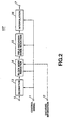
- Fig.2 shows a block diagram showing an example of the noise reducing circuit 107 in the entire structure of Fig.1.
- a decimation circuit 13 is fed e.g., the information on the frame size (resolution) as a control signal from the control circuit 112 comprised of a micro-computer or the like shown in Fig.1.
- the frame size is the standard one of, for example, 352 pixels by 240 lines according to the NTSC system
- a picture signal output of the MPEG decoder 106 of Fig.1 is as shown in Fig.3A, wherein odd-numbered pixels P1, P3, P5, ... are interpolated with even-numbered pixels P0, P2, P4, ...
- An output signal of the decimation circuit 13 is sent to the block distortion reducing circuit 14 for reducing the block distortion produced by performing the decoding operation which is a counterpart operation of the block DCT encoding described above.
- the picture signals from the block distortion reducing circuit 14 are sent to a field recursive type noise reducing circuit 15 for removing the noise, such as block distortion, generated between neighboring fields.
- An output signal of the field recursive type noise reducing circuit 15 is sent to an interpolation circuit 16 so that, if the frame size is of the above-mentioned standard size, the interpolation processing shown at B and C in Fig.3 is executed.
- the resulting interpolated signal is outputted at an output terminal 17.
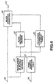
- the block distortion reducing circuit 14 is configured as shown for example in Fig.4.
- picture data processed with compression coding such as block coding
- subsequently decoded for example, picture signals outputted by the MPEG decoder 106 of Fig.1 and obtained via decimation circuit 13 of Fig.2.
- This information processing system is sent to an activity and block step difference calculating circuit 21 and to a block distortion correction circuit 24.
- the activity and block step difference calculating circuit 21 of Fig.4 calculates activity act , as an average value of differences between neighboring pixels in the vicinity of the block boundary, and the block step difference ⁇ b, as a difference between neighboring pixels in the block boundary, and routes these to a block distortion decision circuit 22.
- the block distortion decision circuit 22 performs condition decision, as later explained, using the activity act and the block step difference ⁇ b, for judging whether or not the block distortion exists. If the block distortion is found not to exist, the block distortion correction circuit 24 is responsive to a control signal from the block distortion decision circuit 22 to omit processing of input data entering the terminal 20 and to directly output the data entering the terminal 20 at a terminal 25.
- the activity and block step difference calculating circuit 21 of Fig.4 finds, from the pixel data p supplied to the terminal 20, the activity act , as an average value of differences between neighboring pixels in the vicinity of the block boundary, and the block step difference ⁇ b, as a difference between neighboring pixels in the block boundary.
- the block distortion decision circuit 22 judges the block distortion to have occurred if the condition: act ⁇
- Th denotes a threshold value.
- the magnitude of the block distortion is predicted from the noise quantity prediction table 27, depending on the encoding information from a terminal 26, for example, the value of the quantization step, for varying the threshold value Th.
- Fig.6 shows a graph showing an example of the threshold value Th relative to the quantization step as the encoding information in the noise quantity prediction table 27. The example of Fig.6 exploits characteristics that the rougher the quantization step, the larger becomes the generated noise.
- the block distortion correction circuit 24 directly outputs the input data at the terminal 20 without processing the data.
- the block distortion correction circuit 24 corrects the pixels neighboring to the block boundary and the neighboring pixels for block distortion in accordance with the equations (6) to (13) for removing the block distortion.
- Fig.7 shows an example of the step difference of the block boundary.
- a and B denote the pre-correction state and the post-correction state, respectively.
- the ordinate and the abscissa denote the amplitude, that is pixel data values, and the ordinate denotes the pixel position in the horizontal (H) direction and the vertical (V) direction.
- the step difference ⁇ b of the block boundary of Fig.7A is corrected to the step difference act of the block boundary of Fig.7B.
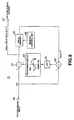
- FIG.8 To an input terminal 60 of Fig.8 are entered picture signals from the block distortion reducing circuit 14 of Fig.2. These input picture signals V in are sent to subtractors 61, 64. An output signal of the subtractor 61 is outputted at an output terminal 67 and written in a field memory 65.
- a memory controller 66 provided in association with the field memory 65, is used for controlling the write and readout operations in or from the field memory 65, such that readout data of the field memory 65 is delayed one field with respect to the write data. That is, if the output signal is denoted V out and the field delay is denoted as F -1 , an output signal of the field memory 65 becomes V out ⁇ F -1 .
- This field-delay output signal is supplied to the subtractor 64, which then subtracts the field-delay output signal V out ⁇ F -1 from the information processing system V in to output the resulting difference signal.
- An output signal of the subtractor 64 is sent via band-limiting low-pass filter (LPF) 63 to a non-linear circuit 62.
- the non-linear circuit 62 is used for multiplying the output signal with a feedback coefficient K depending on the level of an output signal from the LPF 63 (input signal to the non-linear circuit 62).
- This non-linear circuit 62 has input/output characteristics of outputting a field difference of a small range as a noise component and of reducing the large field difference to a zero output on the assumption that such large field difference is derived from movement. That is, the non-linear circuit 62 extracts the noise component by exploiting the characteristics that the noise component has only small field-to-field correlation and has a small amplitude.
- An output signal L ⁇ (V in - V out -F -1 ) of the non-linear circuit 62 is sent to the subtractor 61 so as to be subtracted from the input picture signals V in . This is tantamount to subtracting the noise component extracted by the subtractor 61 from the input picture signals V in for producing the noise-reduced output picture signals V out .
- V out V in - K ⁇ (V in - V out ⁇ F -1 )
- V out ⁇ (1 - K ⁇ F -1 ) V in ⁇ (1-K)
- a contour enhancement circuit as an illustrative example of the picture quality correction circuit 108 of Fig.1, but not in accordance with the invention, is explained with reference to Fig.9.
- Fig.9 shows an illustrative structure of a contour enhancement circuit as the picture quality correction circuit 108.
- an output signal of the noise reducing circuit 107 of Fig.1 is fed to an input terminal 80.
- An input signal from the terminal 80 is sent to a BPF (band-pass filter) 82 and to an adder 85.
- the BPF 82 extracts the mid to high frequency components, such as picture contour components.
- the extracted contour components are sent to a coring circuit 83 so as to be subjected to non-linear processing (coring processing) for removing noise components corresponding to small-amplitude signals.
- the resulting signals are sent to a gain control circuit 84 for controlling a correction amount.
- the resulting signal is sent as a correction signal to an adder 85.
- control signals from a control circuit 112, such as a micro-computer of Fig.1.
- This control signals is sent to the coring circuit 83 and to the gain control circuit 84.
- the operating unit 113 of Fig.1 has a control switch, such as a switch for contour enhancement. The magnitude of the effect of contour enhancement can be controlled by actuating this switch.
- adaptive processing is performed using the weighted encoding information, in the post-processing, carried out in e.g., a contour accentuating circuit.
- the weighted encoding information is used for effecting adaptive processing for contour enhancement.
- Fig.10 shows, in a block diagram, the structure of the contour enhancement circuit in the present modification.
- the control signal supplied from the control circuit 112 via terminal 81 is weighted by a weighting circuit 87b by the value of the quantization step as the encoding information from a terminal 88, and the value of the step difference of the block boundary and the distance from the block boundary as the decoding picture information from a terminal 89.
- G G st ⁇ (K Q /8) ⁇ (L W /4)
- K Q is the weighting coefficient of the quantization step
- L W is the weighting coefficient of the boundary distance
- 1/8, 1/4 are divisors for normalization.
- Fig.11 shows the quantization step weighting coefficients for the quantization step code and the block boundary step difference
- Fig.12 shows the boundary distance weighting coefficients for the block boundary distance.
- the quantization step code and the block boundary step difference are given, such that, from the table of Fig.11, the quantization step weighting coefficient is 4, and the distance from the block boundary is given to the table of Fig.12 to give a value 2 of the boundary distance weighting coefficient.
- the parameter as the control signals supplied from the terminal 81 is weighted by the weighting circuit 87a with the value of the quantization step as the encoding information from the terminal 88 and with the distance from the block boundary and the value of the step difference of the block boundary as the decoding picture information from the terminal 89.
- Fig.13 shows the coring weighting coefficients for the quantization step codes and the block boundary step difference.
- Figs.10 to 13 are merely exemplary and are not intended for limiting the invention.
- the quantization step is varied on the macro-block basis. Therefore, the quantization step difference may be added to the block boundary under consideration.
- the present technique is not limited to the above-described embodiments.
- the foregoing description is directed to the processing in the horizontal (H) direction
- the present invention may similarly be applied to processing in the vertical (V) direction.
- the present technique may be applied not only to processing of luminance signals, but to processing of chroma signals.
Landscapes
- Engineering & Computer Science (AREA)
- Multimedia (AREA)
- Signal Processing (AREA)
- Compression Or Coding Systems Of Tv Signals (AREA)
- Compression, Expansion, Code Conversion, And Decoders (AREA)
- Image Processing (AREA)
- Picture Signal Circuits (AREA)
- Television Signal Processing For Recording (AREA)
- Processing Of Color Television Signals (AREA)
Applications Claiming Priority (3)
| Application Number | Priority Date | Filing Date | Title |
|---|---|---|---|
| JP29391/97 | 1997-02-13 | ||
| JP2939197A JP3800704B2 (ja) | 1997-02-13 | 1997-02-13 | 映像信号処理装置及び方法 |
| JP2939197 | 1997-02-13 |
Publications (2)
| Publication Number | Publication Date |
|---|---|
| EP0859518A1 EP0859518A1 (en) | 1998-08-19 |
| EP0859518B1 true EP0859518B1 (en) | 2004-05-12 |
Family
ID=12274853
Family Applications (1)
| Application Number | Title | Priority Date | Filing Date |
|---|---|---|---|
| EP19980300812 Expired - Lifetime EP0859518B1 (en) | 1997-02-13 | 1998-02-04 | Reduction of noise generated by a digital picture coder/decoder which operates in blocks |
Country Status (6)
| Country | Link |
|---|---|
| US (1) | US6175596B1 (enExample) |
| EP (1) | EP0859518B1 (enExample) |
| JP (1) | JP3800704B2 (enExample) |
| KR (1) | KR100582427B1 (enExample) |
| CN (1) | CN1130918C (enExample) |
| DE (1) | DE69823714T2 (enExample) |
Cited By (1)
| Publication number | Priority date | Publication date | Assignee | Title |
|---|---|---|---|---|
| RU2595756C2 (ru) * | 2009-10-30 | 2016-08-27 | Самсунг Электроникс Ко., Лтд. | Способ и устройство для кодирования и декодирования блока кодирования границы картинки |
Families Citing this family (51)
| Publication number | Priority date | Publication date | Assignee | Title |
|---|---|---|---|---|
| FI106071B (fi) * | 1997-03-13 | 2000-11-15 | Nokia Mobile Phones Ltd | Mukautuva suodatin |
| EP0921691B1 (en) * | 1997-12-04 | 2010-11-24 | Victor Company of Japan, Limited | Video signal processing method and device |
| CN1296703A (zh) | 1999-02-16 | 2001-05-23 | 皇家菲利浦电子有限公司 | 采用过滤来减少块效应的视频解码设备和方法 |
| EP1129579A1 (en) * | 1999-09-14 | 2001-09-05 | Koninklijke Philips Electronics N.V. | Method and device for identifying block artifacts in digital video pictures |
| FI117533B (fi) | 2000-01-20 | 2006-11-15 | Nokia Corp | Menetelmä digitaalisten videokuvien suodattamiseksi |
| US6597723B1 (en) * | 2000-03-21 | 2003-07-22 | Interdigital Technology Corporation | Weighted open loop power control in a time division duplex communication system |
| JP2004505340A (ja) * | 2000-07-19 | 2004-02-19 | キム,ヤン ワン | カードレス安全信用取引処理のためのシステムおよび方法 |
| FR2818862A1 (fr) * | 2000-12-26 | 2002-06-28 | Koninkl Philips Electronics Nv | Procede de traitement de donnees |
| US20070053428A1 (en) * | 2001-03-30 | 2007-03-08 | Vixs Systems, Inc. | Managed degradation of a video stream |
| US8107524B2 (en) * | 2001-03-30 | 2012-01-31 | Vixs Systems, Inc. | Adaptive bandwidth footprint matching for multiple compressed video streams in a fixed bandwidth network |
| WO2002093935A1 (en) * | 2001-05-10 | 2002-11-21 | Matsushita Electric Industrial Co., Ltd. | Image processing apparatus |
| US7773670B1 (en) * | 2001-06-05 | 2010-08-10 | At+T Intellectual Property Ii, L.P. | Method of content adaptive video encoding |
| US6968006B1 (en) | 2001-06-05 | 2005-11-22 | At&T Corp. | Method of content adaptive video decoding |
| US6970513B1 (en) | 2001-06-05 | 2005-11-29 | At&T Corp. | System for content adaptive video decoding |
| US6810086B1 (en) | 2001-06-05 | 2004-10-26 | At&T Corp. | System and method of filtering noise |
| US6909745B1 (en) | 2001-06-05 | 2005-06-21 | At&T Corp. | Content adaptive video encoder |
| US20020191699A1 (en) * | 2001-06-12 | 2002-12-19 | O'brien Royal | Detection system and method for enhancing digital video |
| EP1286551A1 (en) * | 2001-07-17 | 2003-02-26 | Telefonaktiebolaget L M Ericsson (Publ) | Error concealment for image information |
| CN1228732C (zh) * | 2002-01-23 | 2005-11-23 | 佳能株式会社 | 轮廓校正装置、轮廓校正方法 |
| JP3863808B2 (ja) | 2002-05-27 | 2006-12-27 | 三洋電機株式会社 | 輪郭強調回路 |
| US6807317B2 (en) * | 2002-10-25 | 2004-10-19 | Motorola, Inc. | Method and decoder system for reducing quantization effects of a decoded image |
| JP4123356B2 (ja) | 2002-11-13 | 2008-07-23 | 富士ゼロックス株式会社 | 画像処理装置、画像処理プログラム、記憶媒体 |
| KR20040047046A (ko) * | 2002-11-29 | 2004-06-05 | 엘지전자 주식회사 | 동영상 디코더 및 디코딩 방법 |
| US7643688B2 (en) * | 2003-10-10 | 2010-01-05 | Hewlett-Packard Development Company, L.P. | Reducing artifacts in compressed images |
| US20070159556A1 (en) * | 2004-03-25 | 2007-07-12 | Koninklijke Philips Electronics N.V. | Luminance transient improvemet using video encoding metric for digital video processing |
| US7430336B2 (en) * | 2004-05-06 | 2008-09-30 | Qualcomm Incorporated | Method and apparatus for image enhancement for low bit rate video compression |
| JP2006101228A (ja) * | 2004-09-29 | 2006-04-13 | Toshiba Corp | 映像処理装置 |
| WO2006043190A1 (en) * | 2004-10-18 | 2006-04-27 | Koninklijke Philips Electronics N.V. | Deblocking filter for video data |
| JP4534723B2 (ja) * | 2004-11-05 | 2010-09-01 | 株式会社日立製作所 | 画像表示装置、画像処理装置および画像処理方法 |
| JP4715178B2 (ja) * | 2004-11-30 | 2011-07-06 | セイコーエプソン株式会社 | 画像補正装置、画像補正方法およびコンピュータプログラム |
| JP2006179975A (ja) * | 2004-12-20 | 2006-07-06 | Toshiba Corp | 映像信号処理装置、映像信号処理方法及びテレビ放送受信装置 |
| JP2006246249A (ja) * | 2005-03-04 | 2006-09-14 | Toshiba Corp | 映像信号処理装置及び映像信号処理方法 |
| WO2006099743A1 (en) * | 2005-03-25 | 2006-09-28 | Algolith Inc. | Apparatus and method for objective assessment of dct-coded video quality with or without an original video sequence |
| JP5160451B2 (ja) * | 2006-01-31 | 2013-03-13 | トムソン ライセンシング | エッジ・ベースの空間‐時間的フィルタリングの方法および装置 |
| JP4747917B2 (ja) * | 2006-04-03 | 2011-08-17 | 株式会社日立製作所 | デジタル放送受信装置 |
| KR100813068B1 (ko) * | 2006-07-28 | 2008-03-14 | 엘지전자 주식회사 | 전계 강도에 따른 화질 보상 방법 및 장치 |
| KR100696162B1 (ko) * | 2006-08-11 | 2007-03-20 | 엠텍비젼 주식회사 | 이미지의 노이즈 감소 장치 및 노이즈 감소 방법, 이를수행하는 프로그램이 기록된 기록 매체 |
| CN101911501B (zh) * | 2008-01-24 | 2013-07-10 | 日本电信电话株式会社 | 编码方法、解码方法及其装置、以及其程序和记录介质 |
| JP5071721B2 (ja) * | 2008-02-27 | 2012-11-14 | ソニー株式会社 | 画像処理装置および方法、並びにプログラム |
| KR101432227B1 (ko) * | 2008-03-06 | 2014-08-27 | 삼성전자주식회사 | 전자기기에서 비트 해상도 증가 및 에지 강화 방법 및 장치 |
| US8401311B2 (en) | 2008-03-11 | 2013-03-19 | Sony Corporation | Image processing device, method, and program |
| JP5199955B2 (ja) * | 2009-06-16 | 2013-05-15 | キヤノン株式会社 | 画像復号装置及びその制御方法 |
| JP5199956B2 (ja) * | 2009-06-16 | 2013-05-15 | キヤノン株式会社 | 画像復号装置及びその制御方法 |
| JP4703759B2 (ja) * | 2009-11-27 | 2011-06-15 | 株式会社東芝 | 画像処理装置および同装置における画像処理方法 |
| KR101366776B1 (ko) * | 2009-12-07 | 2014-02-21 | 세종대학교산학협력단 | 영상 객체 검출 장치 및 그 방법 |
| JP4762352B1 (ja) | 2010-03-17 | 2011-08-31 | 株式会社東芝 | 画像処理装置及び画像処理方法 |
| JP2010193515A (ja) * | 2010-05-06 | 2010-09-02 | Fujitsu Ltd | 画像処理方法 |
| JP5055408B2 (ja) | 2010-07-16 | 2012-10-24 | シャープ株式会社 | 映像処理装置、映像処理方法、映像処理プログラム、記憶媒体 |
| JP2012191250A (ja) * | 2011-03-08 | 2012-10-04 | Sony Corp | 画像処理装置、画像処理方法、およびプログラム |
| US10492011B1 (en) | 2019-02-19 | 2019-11-26 | Joel E. Haynes | Non-surgical bone conduction hearing aid |
| CN116132759B (zh) * | 2023-04-19 | 2023-09-12 | 深圳市保凌影像科技有限公司 | 一种音视频流同步传输方法、装置、电子设备及存储介质 |
Family Cites Families (16)
| Publication number | Priority date | Publication date | Assignee | Title |
|---|---|---|---|---|
| JP3028553B2 (ja) * | 1990-04-09 | 2000-04-04 | ソニー株式会社 | 画像処理装置及び画像処理方法 |
| US5081692A (en) * | 1991-04-04 | 1992-01-14 | Eastman Kodak Company | Unsharp masking using center weighted local variance for image sharpening and noise suppression |
| US5367629A (en) * | 1992-12-18 | 1994-11-22 | Sharevision Technology, Inc. | Digital video compression system utilizing vector adaptive transform |
| US5473384A (en) * | 1993-12-16 | 1995-12-05 | At&T Corp. | Method of and system for enhancing distorted graphical information |
| JP2673778B2 (ja) * | 1994-02-22 | 1997-11-05 | 国際電信電話株式会社 | 動画像の復号化における雑音低減装置 |
| US5781184A (en) * | 1994-09-23 | 1998-07-14 | Wasserman; Steve C. | Real time decompression and post-decompress manipulation of compressed full motion video |
| EP0721286A3 (en) * | 1995-01-09 | 2000-07-26 | Matsushita Electric Industrial Co., Ltd. | Video signal decoding apparatus with artifact reduction |
| JP3500751B2 (ja) * | 1995-01-20 | 2004-02-23 | ソニー株式会社 | 画像信号処理装置及び撮像装置 |
| US5852475A (en) * | 1995-06-06 | 1998-12-22 | Compression Labs, Inc. | Transform artifact reduction process |
| JP3221291B2 (ja) * | 1995-07-26 | 2001-10-22 | ソニー株式会社 | 画像処理装置、画像処理方法、ノイズ除去装置及びノイズ除去方法 |
| US5819035A (en) * | 1995-10-20 | 1998-10-06 | Matsushita Electric Industrial Co., Ltd. | Post-filter for removing ringing artifacts of DCT coding |
| US5909249A (en) * | 1995-12-15 | 1999-06-01 | General Instrument Corporation | Reduction of noise visibility in a digital video system |
| KR100242636B1 (ko) * | 1996-03-23 | 2000-02-01 | 윤종용 | 블록화효과 및 링잉노이즈 감소를 위한 신호적응후처리시스템 |
| US5737451A (en) * | 1996-04-10 | 1998-04-07 | Eastman Kodak Company | Method and apparatus for suppressing blocking artifacts in block-transform coded images |
| US5933542A (en) * | 1996-04-24 | 1999-08-03 | Sony Corporation | Method and apparatus for blocking effect reduction in images by post-processing in the spatial domain |
| US5990955A (en) * | 1997-10-03 | 1999-11-23 | Innovacom Inc. | Dual encoding/compression method and system for picture quality/data density enhancement |
-
1997
- 1997-02-13 JP JP2939197A patent/JP3800704B2/ja not_active Expired - Fee Related
-
1998
- 1998-02-04 EP EP19980300812 patent/EP0859518B1/en not_active Expired - Lifetime
- 1998-02-04 DE DE1998623714 patent/DE69823714T2/de not_active Expired - Lifetime
- 1998-02-06 US US09/019,947 patent/US6175596B1/en not_active Expired - Lifetime
- 1998-02-13 CN CN98106971A patent/CN1130918C/zh not_active Expired - Fee Related
- 1998-02-13 KR KR1019980004264A patent/KR100582427B1/ko not_active Expired - Fee Related
Cited By (2)
| Publication number | Priority date | Publication date | Assignee | Title |
|---|---|---|---|---|
| RU2595756C2 (ru) * | 2009-10-30 | 2016-08-27 | Самсунг Электроникс Ко., Лтд. | Способ и устройство для кодирования и декодирования блока кодирования границы картинки |
| RU2595613C2 (ru) * | 2009-10-30 | 2016-08-27 | Самсунг Электроникс Ко., Лтд. | Способ и устройство для кодирования и декодирования блока кодирования границы картинки |
Also Published As
| Publication number | Publication date |
|---|---|
| EP0859518A1 (en) | 1998-08-19 |
| KR19980071311A (ko) | 1998-10-26 |
| KR100582427B1 (ko) | 2006-09-27 |
| US6175596B1 (en) | 2001-01-16 |
| DE69823714D1 (de) | 2004-06-17 |
| JP3800704B2 (ja) | 2006-07-26 |
| DE69823714T2 (de) | 2005-04-14 |
| JPH10229546A (ja) | 1998-08-25 |
| CN1130918C (zh) | 2003-12-10 |
| CN1215962A (zh) | 1999-05-05 |
Similar Documents
| Publication | Publication Date | Title |
|---|---|---|
| EP0859518B1 (en) | Reduction of noise generated by a digital picture coder/decoder which operates in blocks | |
| KR100231186B1 (ko) | 화상 데이타의 복호화 처리중에 발생되는 양자화 노이즈 감소방법 및 화상 데이타 복호화 장치 | |
| US5565921A (en) | Motion-adaptive image signal processing system | |
| US6825886B2 (en) | Picture signal processing method and apparatus | |
| US20100284467A1 (en) | Image coding apparatus, image decoding apparatus, image coding method, and image decoding method | |
| US6904096B2 (en) | Video data processing device and video data processing method | |
| JPH11196419A5 (enExample) | ||
| US20080031336A1 (en) | Video decoding apparatus and method | |
| JPWO1998054892A1 (ja) | ブロック歪低減方法及び装置並びに符号化方法及び装置 | |
| JP3961600B2 (ja) | ブロック歪低減方法及び装置 | |
| JP2000013643A (ja) | ノイズ低減装置および方法、映像信号処理装置、並びに動き検出方法 | |
| JP2004518338A (ja) | 符号化されたビデオの鮮鋭度を向上する方法及びシステム | |
| US7161633B2 (en) | Apparatus and method for providing a usefulness metric based on coding information for video enhancement | |
| KR20050074906A (ko) | 루프 필터링 방법 및 루프 필터 | |
| US6781637B2 (en) | Image change detecting apparatus and image change detecting method, image encoding apparatus and information recording medium with image change detecting program recorded readable by computer | |
| US8929439B2 (en) | Compressed image noise removal device and reproduction device | |
| JPH10276433A (ja) | ブロックノイズ除去装置 | |
| JPH09130648A (ja) | 動画像信号処理装置 | |
| KR0172902B1 (ko) | 엠펙 ii 부호기 | |
| JP2001094996A (ja) | ブロック歪低減方法及びブロック歪低減装置 | |
| JPH10191332A (ja) | ブロック歪低減装置及び方法 | |
| KR100217148B1 (ko) | 영상 데이타의 복호 처리중에 발생하는 모스키토 노이즈를 줄이는 방법 및 이 방법을 사용한 영상데이타의 복호장치 | |
| KR100205293B1 (ko) | Mpeg 비디오 복호기에서 블록 효과 제거 회로 및 방법 | |
| JPH0738896A (ja) | 動画像領域分割符号化装置 | |
| JP2008301366A (ja) | 画像復号化装置、及び画像復号化方法 |
Legal Events
| Date | Code | Title | Description |
|---|---|---|---|
| PUAI | Public reference made under article 153(3) epc to a published international application that has entered the european phase |
Free format text: ORIGINAL CODE: 0009012 |
|
| AK | Designated contracting states |
Kind code of ref document: A1 Designated state(s): DE FR GB IT |
|
| AX | Request for extension of the european patent |
Free format text: AL;LT;LV;MK;RO;SI |
|
| 17P | Request for examination filed |
Effective date: 19990216 |
|
| AKX | Designation fees paid |
Free format text: DE FR GB IT |
|
| RBV | Designated contracting states (corrected) |
Designated state(s): DE FR GB IT |
|
| 17Q | First examination report despatched |
Effective date: 20020715 |
|
| GRAP | Despatch of communication of intention to grant a patent |
Free format text: ORIGINAL CODE: EPIDOSNIGR1 |
|
| GRAS | Grant fee paid |
Free format text: ORIGINAL CODE: EPIDOSNIGR3 |
|
| GRAA | (expected) grant |
Free format text: ORIGINAL CODE: 0009210 |
|
| AK | Designated contracting states |
Kind code of ref document: B1 Designated state(s): DE FR GB IT |
|
| REG | Reference to a national code |
Ref country code: GB Ref legal event code: FG4D |
|
| REF | Corresponds to: |
Ref document number: 69823714 Country of ref document: DE Date of ref document: 20040617 Kind code of ref document: P |
|
| ET | Fr: translation filed | ||
| PLBE | No opposition filed within time limit |
Free format text: ORIGINAL CODE: 0009261 |
|
| STAA | Information on the status of an ep patent application or granted ep patent |
Free format text: STATUS: NO OPPOSITION FILED WITHIN TIME LIMIT |
|
| 26N | No opposition filed |
Effective date: 20050215 |
|
| REG | Reference to a national code |
Ref country code: GB Ref legal event code: 746 Effective date: 20120703 |
|
| REG | Reference to a national code |
Ref country code: DE Ref legal event code: R084 Ref document number: 69823714 Country of ref document: DE Effective date: 20120614 |
|
| PGFP | Annual fee paid to national office [announced via postgrant information from national office to epo] |
Ref country code: DE Payment date: 20140219 Year of fee payment: 17 |
|
| PGFP | Annual fee paid to national office [announced via postgrant information from national office to epo] |
Ref country code: IT Payment date: 20140221 Year of fee payment: 17 Ref country code: FR Payment date: 20140219 Year of fee payment: 17 |
|
| PGFP | Annual fee paid to national office [announced via postgrant information from national office to epo] |
Ref country code: GB Payment date: 20140218 Year of fee payment: 17 |
|
| REG | Reference to a national code |
Ref country code: DE Ref legal event code: R119 Ref document number: 69823714 Country of ref document: DE |
|
| GBPC | Gb: european patent ceased through non-payment of renewal fee |
Effective date: 20150204 |
|
| REG | Reference to a national code |
Ref country code: FR Ref legal event code: ST Effective date: 20151030 |
|
| PG25 | Lapsed in a contracting state [announced via postgrant information from national office to epo] |
Ref country code: IT Free format text: LAPSE BECAUSE OF NON-PAYMENT OF DUE FEES Effective date: 20150204 |
|
| PG25 | Lapsed in a contracting state [announced via postgrant information from national office to epo] |
Ref country code: GB Free format text: LAPSE BECAUSE OF NON-PAYMENT OF DUE FEES Effective date: 20150204 Ref country code: DE Free format text: LAPSE BECAUSE OF NON-PAYMENT OF DUE FEES Effective date: 20150901 |
|
| PG25 | Lapsed in a contracting state [announced via postgrant information from national office to epo] |
Ref country code: FR Free format text: LAPSE BECAUSE OF NON-PAYMENT OF DUE FEES Effective date: 20150302 |