EP0859384B1 - Transformator und seine Verwendung, und Transformatormontageverfahren. - Google Patents
Transformator und seine Verwendung, und Transformatormontageverfahren. Download PDFInfo
- Publication number
- EP0859384B1 EP0859384B1 EP98102447A EP98102447A EP0859384B1 EP 0859384 B1 EP0859384 B1 EP 0859384B1 EP 98102447 A EP98102447 A EP 98102447A EP 98102447 A EP98102447 A EP 98102447A EP 0859384 B1 EP0859384 B1 EP 0859384B1
- Authority
- EP
- European Patent Office
- Prior art keywords
- adhesive
- transformer
- winding fixture
- substrate
- secondary winding
- Prior art date
- Legal status (The legal status is an assumption and is not a legal conclusion. Google has not performed a legal analysis and makes no representation as to the accuracy of the status listed.)
- Expired - Lifetime
Links
Images


Classifications
-
- H—ELECTRICITY
- H05—ELECTRIC TECHNIQUES NOT OTHERWISE PROVIDED FOR
- H05K—PRINTED CIRCUITS; CASINGS OR CONSTRUCTIONAL DETAILS OF ELECTRIC APPARATUS; MANUFACTURE OF ASSEMBLAGES OF ELECTRICAL COMPONENTS
- H05K1/00—Printed circuits
- H05K1/02—Details
- H05K1/0271—Arrangements for reducing stress or warp in rigid printed circuit boards, e.g. caused by loads, vibrations or differences in thermal expansion
-
- B—PERFORMING OPERATIONS; TRANSPORTING
- B41—PRINTING; LINING MACHINES; TYPEWRITERS; STAMPS
- B41J—TYPEWRITERS; SELECTIVE PRINTING MECHANISMS, i.e. MECHANISMS PRINTING OTHERWISE THAN FROM A FORME; CORRECTION OF TYPOGRAPHICAL ERRORS
- B41J29/00—Details of, or accessories for, typewriters or selective printing mechanisms not otherwise provided for
- B41J29/38—Drives, motors, controls or automatic cut-off devices for the entire printing mechanism
- B41J29/393—Devices for controlling or analysing the entire machine ; Controlling or analysing mechanical parameters involving printing of test patterns
-
- H—ELECTRICITY
- H01—ELECTRIC ELEMENTS
- H01F—MAGNETS; INDUCTANCES; TRANSFORMERS; SELECTION OF MATERIALS FOR THEIR MAGNETIC PROPERTIES
- H01F27/00—Details of transformers or inductances, in general
- H01F27/06—Mounting, supporting or suspending transformers, reactors or choke coils not being of the signal type
-
- H—ELECTRICITY
- H01—ELECTRIC ELEMENTS
- H01F—MAGNETS; INDUCTANCES; TRANSFORMERS; SELECTION OF MATERIALS FOR THEIR MAGNETIC PROPERTIES
- H01F27/00—Details of transformers or inductances, in general
- H01F27/24—Magnetic cores
- H01F27/26—Fastening parts of the core together; Fastening or mounting the core on casing or support
- H01F27/266—Fastening or mounting the core on casing or support
-
- H—ELECTRICITY
- H01—ELECTRIC ELEMENTS
- H01F—MAGNETS; INDUCTANCES; TRANSFORMERS; SELECTION OF MATERIALS FOR THEIR MAGNETIC PROPERTIES
- H01F27/00—Details of transformers or inductances, in general
- H01F27/28—Coils; Windings; Conductive connections
- H01F27/29—Terminals; Tapping arrangements for signal inductances
- H01F27/292—Surface mounted devices
-
- H—ELECTRICITY
- H01—ELECTRIC ELEMENTS
- H01F—MAGNETS; INDUCTANCES; TRANSFORMERS; SELECTION OF MATERIALS FOR THEIR MAGNETIC PROPERTIES
- H01F27/00—Details of transformers or inductances, in general
- H01F27/28—Coils; Windings; Conductive connections
- H01F27/32—Insulating of coils, windings, or parts thereof
- H01F27/327—Encapsulating or impregnating
-
- H—ELECTRICITY
- H01—ELECTRIC ELEMENTS
- H01F—MAGNETS; INDUCTANCES; TRANSFORMERS; SELECTION OF MATERIALS FOR THEIR MAGNETIC PROPERTIES
- H01F41/00—Apparatus or processes specially adapted for manufacturing or assembling magnets, inductances or transformers; Apparatus or processes specially adapted for manufacturing materials characterised by their magnetic properties
- H01F41/005—Impregnating or encapsulating
-
- H—ELECTRICITY
- H01—ELECTRIC ELEMENTS
- H01F—MAGNETS; INDUCTANCES; TRANSFORMERS; SELECTION OF MATERIALS FOR THEIR MAGNETIC PROPERTIES
- H01F41/00—Apparatus or processes specially adapted for manufacturing or assembling magnets, inductances or transformers; Apparatus or processes specially adapted for manufacturing materials characterised by their magnetic properties
- H01F41/02—Apparatus or processes specially adapted for manufacturing or assembling magnets, inductances or transformers; Apparatus or processes specially adapted for manufacturing materials characterised by their magnetic properties for manufacturing cores, coils, or magnets
- H01F41/04—Apparatus or processes specially adapted for manufacturing or assembling magnets, inductances or transformers; Apparatus or processes specially adapted for manufacturing materials characterised by their magnetic properties for manufacturing cores, coils, or magnets for manufacturing coils
- H01F41/12—Insulating of windings
- H01F41/127—Encapsulating or impregnating
-
- H—ELECTRICITY
- H01—ELECTRIC ELEMENTS
- H01F—MAGNETS; INDUCTANCES; TRANSFORMERS; SELECTION OF MATERIALS FOR THEIR MAGNETIC PROPERTIES
- H01F27/00—Details of transformers or inductances, in general
- H01F27/28—Coils; Windings; Conductive connections
- H01F27/29—Terminals; Tapping arrangements for signal inductances
- H01F2027/297—Terminals; Tapping arrangements for signal inductances with pin-like terminal to be inserted in hole of printed path
-
- H—ELECTRICITY
- H05—ELECTRIC TECHNIQUES NOT OTHERWISE PROVIDED FOR
- H05K—PRINTED CIRCUITS; CASINGS OR CONSTRUCTIONAL DETAILS OF ELECTRIC APPARATUS; MANUFACTURE OF ASSEMBLAGES OF ELECTRICAL COMPONENTS
- H05K1/00—Printed circuits
- H05K1/18—Printed circuits structurally associated with non-printed electric components
-
- H—ELECTRICITY
- H05—ELECTRIC TECHNIQUES NOT OTHERWISE PROVIDED FOR
- H05K—PRINTED CIRCUITS; CASINGS OR CONSTRUCTIONAL DETAILS OF ELECTRIC APPARATUS; MANUFACTURE OF ASSEMBLAGES OF ELECTRICAL COMPONENTS
- H05K2201/00—Indexing scheme relating to printed circuits covered by H05K1/00
- H05K2201/09—Shape and layout
- H05K2201/09818—Shape or layout details not covered by a single group of H05K2201/09009 - H05K2201/09809
- H05K2201/0999—Circuit printed on or in housing, e.g. housing as PCB; Circuit printed on the case of a component; PCB affixed to housing
-
- H—ELECTRICITY
- H05—ELECTRIC TECHNIQUES NOT OTHERWISE PROVIDED FOR
- H05K—PRINTED CIRCUITS; CASINGS OR CONSTRUCTIONAL DETAILS OF ELECTRIC APPARATUS; MANUFACTURE OF ASSEMBLAGES OF ELECTRICAL COMPONENTS
- H05K2201/00—Indexing scheme relating to printed circuits covered by H05K1/00
- H05K2201/10—Details of components or other objects attached to or integrated in a printed circuit board
- H05K2201/10227—Other objects, e.g. metallic pieces
- H05K2201/10409—Screws
-
- H—ELECTRICITY
- H05—ELECTRIC TECHNIQUES NOT OTHERWISE PROVIDED FOR
- H05K—PRINTED CIRCUITS; CASINGS OR CONSTRUCTIONAL DETAILS OF ELECTRIC APPARATUS; MANUFACTURE OF ASSEMBLAGES OF ELECTRICAL COMPONENTS
- H05K2201/00—Indexing scheme relating to printed circuits covered by H05K1/00
- H05K2201/10—Details of components or other objects attached to or integrated in a printed circuit board
- H05K2201/10431—Details of mounted components
- H05K2201/10568—Integral adaptations of a component or an auxiliary PCB for mounting, e.g. integral spacer element
-
- H—ELECTRICITY
- H05—ELECTRIC TECHNIQUES NOT OTHERWISE PROVIDED FOR
- H05K—PRINTED CIRCUITS; CASINGS OR CONSTRUCTIONAL DETAILS OF ELECTRIC APPARATUS; MANUFACTURE OF ASSEMBLAGES OF ELECTRICAL COMPONENTS
- H05K2201/00—Indexing scheme relating to printed circuits covered by H05K1/00
- H05K2201/20—Details of printed circuits not provided for in H05K2201/01 - H05K2201/10
- H05K2201/2036—Permanent spacer or stand-off in a printed circuit or printed circuit assembly
-
- H—ELECTRICITY
- H05—ELECTRIC TECHNIQUES NOT OTHERWISE PROVIDED FOR
- H05K—PRINTED CIRCUITS; CASINGS OR CONSTRUCTIONAL DETAILS OF ELECTRIC APPARATUS; MANUFACTURE OF ASSEMBLAGES OF ELECTRICAL COMPONENTS
- H05K3/00—Apparatus or processes for manufacturing printed circuits
- H05K3/30—Assembling printed circuits with electric components, e.g. with resistor
- H05K3/306—Lead-in-hole components, e.g. affixing or retention before soldering, spacing means
Definitions
- the present invention relates to a transformer assembling method, a transformer, and a transformer-mounted substrate, or to an art most preferably applicable to, for example, a transformer for switching power supply units using a ferrite core. More particularly, this invention is concerned with a power supply unit having a components-mounted substrate or a power supply unit included in a recording apparatus, for example, an AC adaptor used as a power supply for electronic equipment or a power supply unit connected to the AC adaptor.
- a switching power supply unit can be designed to be more compact and lightweight than a dropper power supply unit, and has the advantage of exhibiting high conversion efficiency.
- the switching power supply unit is therefore widely adopted for various usages ranging from the usage as a built-in power supply to be incorporated in a compact equipment to the usage as an AC adaptor. Since the switching power supply unit has thus prevailed, various kinds of electronic equipment that are compact and lightweight can be readily carried about with females or children. The contribution of the switching power supply unit to industries has been highly appreciated.
- a transformer to be mounted on a substrate for this kind of switching power supply unit will be described briefly.
- a coil 103 is formed on a bobbin 102, and a core 101 is inserted into the bore of the bobbin 102a.
- an adhesive is applied to illustrated regions or the transformer is impregnated with a varnish as shown in Fig. 48 .
- a finished good is completed.
- the transformer 100 is designed to be relatively flat, and mounted on a substrate.
- the transformer contributes to a compact and lightweight design of a power supply.
- the transformer 100 designed to be compact and lightweight and mounted on a substrate is incorporated in a power supply unit, there arises a problem that it may incur an excessive impact load because of improper handling during transportation.
- the transformer 100 designed to be compact and lightweight and mounted on a substrate is incorporated in a power supply to be used as an AC adaptor placed on a desktop, since a power cord may be hooked to cause such an event that the power supply falls off the desktop, unprecedented measures must be taken in order to enable the power supply to resist an excessive impact load.
- the broken state of a transformer is serious when an external force works, as shown in Fig. 43 , on a components-mounted substrate 20 in a direction of an arrow F.
- a moment oriented in a direction of an arrow M works on a transformer 100.
- a tensile force acts abruptly on one of thin parts 102a of the bobbin 102 firmly soldered to the pattern-printed area of the substrate 20 via lead pins 12 connected to the secondary winding of the transformer 100.
- a breakdown phenomenon or a phenomenon that a transformer is ruptured at the thin part 102a thereof takes place.
- a countermeasure against the rupture is such that the thin parts 102a united with both ends of the coil 103 formed on the bobbin are, as shown in Fig. 44A that is the front view of the bobbin 102 and Fig. 44B that is the right-hand side view of the bobbin, chamfered for the purpose of reinforcement.
- the anti-breakdown strength of the bobbin 102 is thus improved.
- ribs are interposed between radiating plates that are components to be mounted on a substrate. Even when the substrate is dropped, the ribs prevent the substrate from deforming to an extent exceeding a limit. The anti-impact resistivity of the substrate is thus improved.
- a containing means included in a power supply unit is composed of an upper case and lower case which are separated from each other up and down with a substrate between them. Supporting members are extended from the upper case and lower case in order to immobilize the substrate horizontally and vertically.
- FIG. 45 shows an example of a known holding structure for a substrate.
- upper and lower cases 213 and 214 for an AC adaptor
- a substrate 220 to be held by the cases screws 221 for tightening the upper case 213 and lower case 214
- a transformer 100 for tightening the upper case 213 and lower case 214
- radiating plates 222 and 223 for tightening the upper case 213 and lower case 214
- an aluminum electrolytic capacitor 225 On each radiating plate, heat-dissipation components, for example, a power transistor, FET, and diode are fixed using screws.
- Ribs 213b that are supporting members successively extending from the upper case 213 are abutting on the substrate 220 and thus locking it.
- Ribs 214b are successively formed on the lower case 214, and abutting on and holding the bottom of the substrate 220. This helps the substrate 220 resist an impact load including a drop, and prevents deformation-based breakdown of the substrate 220.
- a containing means of a power supply unit is composed of an upper case and lower case that are separated from each other up and down with a substrate between them. Supporting members are extended from the upper case and lower case in order to immobilize the substrate horizontally and vertically.
- Fig. 46 is a sectional view showing a major portion of a transformer 100 that has been generally adopted in the past.
- the transformer and a core are impregnated with a varnish and thus secured.
- a coil 103 is formed on a bobbin 102, and a core 101 is inserted into the bore of the bobbin 102.
- adhesives 105 and 106 are applied to illustrated regions. This results in a finished good.
- Fig. 48 the whole outer circumference of the transformer is coated with a varnish 108, whereby a finished good is completed.
- the transformer 100 is placed to be relatively flat-and then mounted on a substrate.
- the transformer contributes to a compact and lightweight design of a power supply.
- Figs. 47 and 48 are oblique views of the appearance of a transformer 100 that has generally been adopted in the past.
- Fig. 47 shows a transformer of a type having a core secured using adhesives
- Fig. 48 shows a transformer of a type having a core secured using a varnish with which the transformer is impregnated.
- a coil 103 is formed on a bobbin 102, and a core 101 is inserted into the bore of the bobbin 102. Thereafter, adhesives 105 and 106 are applied to illustrated regions in order to secure the core, whereby a finished good is completed.
- Fig. 48 the whole outer circumference of the transformer is coated with a varnish 108, whereby a finished good is completed.
- the transformer 100 is designed to be relatively flat and then mounted on a substrate.
- the structure constitutes to a compact and lightweight design of a power supply.
- a power cord When a power supply including the transformer 100 designed to be compact and lightweight and mounted on a substrate is used as an AC adaptor placed on a desktop, a power cord may be hooked to cause such an event that the power supply falls off the desktop. This makes it necessary to take unprecedented measures.
- the broken state of a transformer is serious when an external force works, as shown in Fig. 43 , on a components-mounted substrate 20 in a direction of an arrow F.
- a moment oriented in a direction of an arrow M acts on the transformer 100.
- a tensile force is applied abruptly to one of thin parts 102a of the bobbin 102 fixed to a pattern-printed area of the substrate 20 by way of lead pins 11 and 12 of the transformer 100.
- a breakdown phenomenon or a phenomenon that a transformer is ruptured at the thin part 102a takes place.
- a countermeasure against the rupture is such that the thin parts 102a united with both ends of the coil 103 formed on the bobbin are chamfered for the purpose of reinforcement.
- the anti-breakdown strength of the bobbin 102 is thus improved
- Another fixing method is, as disclosed in Japanese Unexamined Patent Publication No. 6-96965 or 6-163278 , such that a transformer itself is stowed in a housing case for holding the whole transformer and gaps are filled with a resin.
- the method for improving anti-breakdown strength by chamfering the thin parts 102a of the bobbin 102 has a problem that since the precision in outer dimensions of a ferrite core employed greatly differs from one to another, a gap may be created by the side of a ferrite core and the transformer may therefore fail to resist an excessive impact load such as a drop.
- An object of the present invention is to provide a transformer assembling method, a transformer, and a transformer-mounted substrate in which the anti-breakdown strength of a transformer can be improved, the performance of a ferrite core can be drawn out fully, and the transformer can be designed to be compact and lightweight. More particularly, an object of the present invention is to provide a transformer capable of being produced to resist a drop according to the on-going process of manufacturing a transformer without the use of any special component or material.
- Another object of the present invention is to provide a transformer assembling method, a transformer, and a transformer-mounted substrate in which the anti-breakdown strength of a transformer can be improved, the performance of a ferrite core can be fully drawn out, and the transformer can be designed to be compact and lightweight.
- Another object of the present invention is to provide a power supply unit in which when an impact load is applied, a substrate is deformed properly at a large radius of curvature but a stress larger than a breaking stress will not be imposed on mounted components, and a recording apparatus including the power supply unit.
- an AC adaptor is often used as a power supply.
- an event that the AC adaptor is dropped because of routing of a cable or the compact design of the AC adaptor often takes place.
- the present invention also attempts to cope with the event.
- the supply voltage for compact electronic equipment including the recording apparatus is different from nation to nation.
- a power supply unit suitable for a destination to which an equipment is delivered must be included in the equipment.
- the compact electronic equipment including the recording apparatus often adopt a detachable AC adaptor as a power supply unit due to the easiness in production and management. This is intended to pack an electronic equipment and AC adaptor immediately according to a market trend and then deliver them to a destination.
- the AC adaptor is not attached to a main unit of the equipment but packed together with the main unit.
- a user purchases the thus packed product, unpacks it, and attach the AC adaptor to the main unit. At this time, an excessive impact load may be imposed on the AC adaptor because of improper handling of the AC adaptor during transportation. This is an unprecedented problem.
- the present invention attempts to facilitate the common use of a main unit and power supply.
- Fig. 1 is a sectional view showing a major portion in accordance with the first example of the present invention.
- a substrate 20 on which electronic components are mounted is shaped as illustrated by using a given resin material, and used to construct an AC adaptor serving as a power supply unit.
- Bosses 13a and 14a for screwing upper and lower cases 13 and 14 so as to join the upper and lower cases with the substrate between them are formed as illustrated, whereby the substrate 20 is immobilized and locked horizontally.
- ribs 13b and 14b serving as stoppers that are restraining members for restricting deformation are molded as parts of the cases, so that an excessive deformation leading to a breakdown can be prevented in case the substrate is deformed by an impact load or the like.
- the upper and lower cases 13 and 14 are secured with the substrate 20 between them by tightening screws 21 and thus united with each other.
- This assembly is handled as a power supply unit and can be replaced with another.
- a transformer 10 that is heavier than the other mounted components is mounted so that primary winding pins 11 and secondary winding pins 12 are, as illustrated, arranged in the longitudinal direction of the substrate 20.
- heat-dissipation components for example, a power transistor, FET, and diode are screwed to radiating plates 22 and 23 mounted on the substrate 20.
- fixing terminals 22a, 22b, 23a, and 23b are inserted into though holes bored in the substrate 20 and then firmly soldered to patterned lands. Thus, mechanical strength is ensured.
- An aluminum electrolytic capacitor 25 is mounted between the radiating plates 22 and 23 by soldering leads 25a and 25b as illustrated.
- the heights of the ends of the ribs from the substrate are determined so that gaps g1, g2, g3, and g4 can be, as illustrated, defined between the ends of the ribs 13b and 14b and the face and back of the substrate 20.
- the substrate 20 may be temporarily warped upward in the drawing. Nevertheless, only when the magnitude of displacement corresponds to the gap g1 or g2, the substrate comes into contact with the ribs 13b and is prevented from deforming further. The substrate can therefore be prevented from breaking down.
- the AC adaptor undergoes an impact oriented in a direction opposite to the above direction
- the substrate 20 comes into contact with the ribs 14b serving as stoppers and is prevented from further deforming and breaking down.
- the dimensions of the gaps g1, g2, g3, and g4 can be determined freely according'to the degree by which the substrate may be deformed. Whatever kind of impact can therefore be coped with.
- the positions of the ribs can be determined optimally in consideration of the positions of components mounted on the substrate.
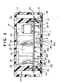
- Fig. 2 is a sectional view showing a major portion in accordance with the second example of the present invention.
- the same reference numerals are assigned to the components that have already been described. The description of the components will be omitted.
- the radiating plates 22 and 23 dissipate heat when a heat-generate component, for example, a power transistor 26 is screwed to them.
- the heights of the radiating plates from the substrate are determined so that gaps g5 and g6 will be created between the radiating plates and the inner wall surface of the upper case 13.
- the fixing terminals 22a, 22b, 23a, and 23b used to fix the radiating plates to the substrate 20 are, as illustrated, extending downward. Gaps g7, g8, g9, g10, g11, and g12 are created between the fixing terminals and the inner wall surface of the lower case 14.
- the ends 22aa and 22bb of the fixing terminals 22a and 22b used to fix the radiating plate to the substrate abut on the inner wall of the lower case 14. This prevents the substrate from deforming further.
- the necessity of ribs can be obviated.
- the dimensions of the gaps g5 to g12 can be determined independently according to the degree by which the substrate may be deformed.
- Fig. 4 is an oblique view showing the third example.
- lead terminals 25a and 25b for the aluminum electrolytic capacitor 25 there are shown lead terminals 25a and 25b for the aluminum electrolytic capacitor 25, lands 20a for soldering included in a pattern printed on the back of the substrate 20 that is the surface thereof to be soldered, and copper-foil exposed parts 20b not coated with a resist.
- the copper-foil exposed parts are coated with solder during flowing or reflowing.
- the coating helps improve the strength of the surfaces of feeble parts of the substrate. Eventually, the flexural strength of the substrate can be improved partly.
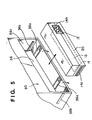
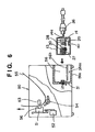
- Fig. 5 is an oblique view showing the fourth example.
- Fig. 6 is a sectional view of the structure shown in Fig. 5 .
- a connecting means is included for making it possible to freely attach or detach the assembly to or from a power supply stowage 56 of an ink-jet printer 50 that is a recording apparatus, and for mechanically and electrically connecting the assembly to the power supply stowage.
- the substrate 20 when an impact load oriented vertically is imposed on the printer 50, the substrate 20 is displaced by a given magnitude in order to absorb the impact.
- a displacement whose magnitude is equal to or larger than the given magnitude is restrained by the ribs 13b and 14b shown in Fig. 1 and others, whereby the impact load is dispersed.
- the power supply stowage 56 therefore includes, as illustrated, locking hooks 56a used for mechanical locking the containing means and side guiding projections 56b.
- a guide ditch 14c is bored in both side surfaces of the power supply unit (AC adaptor), and an opening 14h serving as an inlet 15 is formed in the back of the AC adaptor.
- An inlet 36 shown in Fig. 6 is joined with the inlet 15.
- the printer 50 and AC adaptor are mutually separated.
- the printer and AC adaptor are united.
- concave locking portions 14c are formed in the bottom of the lower case 14 of the AC adaptor.
- the AC adaptor is locked.
- a DC connector 30 to be plugged in a socket 31 formed inside the power supply stowage 56 of the printer 50 is mounted on a second substrate 27 connected to the substrate 20 over a power line 28.
- the connecting means is included for making it possible to freely attach or detach the AC adaptor to or from the power supply stowage 56 of the ink-jet printer 50, and for mechanically and electrically connecting the AC adaptor to the power supply stowage.
- the AC adaptor is therefore freely attachable or detachable.
- the impact load is imposed only on the substrate 20. Since the socket 31 is mechanically separated from the substrate by means of the power line 28, no load is applied to the socket.
- a carriage 51 engaged with a screw ditch for a lead screw to be rotated by a driving force conveyer gear responsively to the forward or reverse rotation of a driving motor 52 has a pin (not shown) and is reciprocated over the face and back of paper.
- the carriage 51 has an ink-jet cartridge 56 mounted thereon.
- Paper 55 is pressed against a platen 53 by a paper presser along with the movement of the carriage, and driven by a given magnitude by means of a roller 54.
- Capping, cleaning, and suction and restoration are carried out at associated positions due to the operation of the lead screw when the carriage comes to a home position. Anyhow, the capping, cleaning, and suction and restoration should merely be carried out according to known timing.
- the recording apparatus in accordance with the present invention may be of a type that serves as an image output terminal and that is united with or separated from an information processing equipment such as a computer, a type serving as a copier including a reader or the like, or a type serving as a facsimile system having the transmission and reception functions.
- the substrate should merely be designed so that a radius of curvature at a point on the substrate to be observed when the substrate is deformed will be large. When the substrate is held in a narrow space, even if the substrate is deformed little, the radius of curvature becomes small. Therefore, efforts should be made not to hold the substrate in a narrow space.
- an AC adaptor is often used as the power supply.
- recording apparatuses designed for use at offices or on desks employ the AC adaptor.
- the AC adaptor may be accidentally dropped during routing of a cable or during handling because of the compact design. According to the present invention, such an event can be prevented.
- a main unit of the printer is requested to be used in common. It is also requested that a power supply can be used in common and an equipment can be handled easily. For meeting these requests, it is considered to make the equipment cordless. Removing a power cord is thought to reduce cost at the same time. From these viewpoints, the main unit, power supply, and cord are supplied separately, and the main unit and power supply are used in common. A printer and power supply suitable for a destination are selected and then assembled by a user. Owing to this system, destinations can be managed easily, and the delivery of an equipment; in a cordless state in which the equipment can be handled easily can be realized.
- the system will prove advantageous especially when a printer and AC adaptor are assembled by a user. Since the AC adaptor is a separate unit until a user assembles the AC adaptor and printer, the AC adaptor may undergo an impact load such as a drop. The AC adaptor must be protected from the impact load.
- An AC adaptor having excellent anti-impact strength can be provided separately from a main equipment such as a recording apparatus or printer. This enables common use of the main unit and AC adaptor. Destinations of products can be managed readily, and products having excellent structures can be provided. When ribs are employed, an AC adaptor having excellent anti-impact strength can be realized without an increase in cost. When components such as radiating plates and a transformer are employed, an AC adaptor having excellent anti-impact strength can be realized without any impairment of the appearance of a housing.
- a power supply unit in which when an impact load is applied, a substrate is deformed properly at a large radius of curvature and in which a stress equal to or larger than a breaking stress will not be imposed on mounted components, and a recording apparatus including the power supply unit.
- a main unit of the recording apparatus and a power supply can be used in common.
- Fig. 7 is a plan view showing the structure of a transformer in accordance with the fifth example
- Fig. 8 is a front view of the structure shown in Fig. 7
- the transformer employed in a switching power supply unit is, as illustrated, composed of a core 1 made of a ferrite, a bobbin made of a resin and used to wind a wound material, and a winding member that is a coil made by winding a wound material used to form windings, an inter-layer insulating tape, and a barrier tape used to space the primary and secondary windings in order to meet safety standards according to a given winding method.
- An adhesive 4 that is an affixing means for securing the bobbin 2 and core 1 is applied to a total of four regions at the ends of the primary winding and secondary winding on collars 2a of the bobbin 2.
- An epoxy adhesive that is a thermosetting adhesive is used as the adhesive 4.
- an adhesive-5 is applied to junctions between members constituting the core 1.
- An adhesive 6 is applied to a junction between an upper end 2b of the bobbin 2 at the end of the secondary winding and the core 1.
- the transformer 10 reinforced using the adhesives 4, 5, and 6 is mounted on the substrate 20.
- Various drop tests were conducted on the transformer in comparison with a transformer whose core 1 and bobbin 2 were not secured.
- the core 1 and bobbin 2 were not secured at regions on the margins of the bobbin.
- the core 1 was thought to crack.
- the thin part 102a shown in Fig. 43 cracked. It was confirmed that a moment M or an excessive impact was concentrated on the transformer, which was relatively heavy, in a direction of an arrow in Fig. 4 , the bobbin 2 could not resist the moment or impact and was relatively readily ruptured near the portion of the winding member from which the lead pins are extending. Consequently, it has been revealed that the core 1 has sufficient anti-impact resistivity but the strength of the bobbin 2 is insufficient.
- an adhesive 106 is applied to one side of a bobbin as shown in Fig. 16 .
- the adhesive 4 that is an epoxy adhesive is, as shown in Figs. 7 and 8 , applied to the four regions on the collars 2a of the bobbin at the ends of the primary winding and secondary winding in order to secure the bobbin 2 and core 1.
- the strength of adhesive bonding between the bobbin 2 and core 1 is increased in order to disperse a breaking force applied to the bobbin 2, such as, a moment M or impact load stemming from a drop.
- the epoxy adhesive that is an affixing means for securing the bobbin 2 and core 1 is a thermosetting adhesive. Natural hardening is facilitated due to heat dissipated during self-heating occurring when the transformer in the power supply unit is actuated.
- the thermosetting adhesive has the merit that since the heat conductivity of the thermosetting adhesive is excellent, the strength of adhesive bonding exhibited by the thermosetting adhesive will, unlike that exhibited by a thermoplastic adhesive, not deteriorate.
- Fig. 9 that is a plan view showing the structure of a transformer in accordance with the sixth example
- Fig. 10 that is a front view of the structure shown in Fig. 9
- the same reference numerals are assigned to the components that have been described. The description of the components will be omitted, but a difference from the aforesaid embodiments will be described.
- the adhesive 4 used to secure the bobbin 2 and core 1 is applied to positions on the collars 2a at the ends of the primary winding and secondary winding, that is, the surfaces opposed to the core 1 and in contact with the bobbin 2 which include at least four corners of the bobbin 2.
- the adhesive 4 used to secure the bobbin 2 and core 1 is applied to positions, which include at least four corners of the bobbin 2, on side surfaces 2c of the bobbin at the ends of the primary winding and secondary winding along lines, along which the core and bobbin are joined with each other, on the outer circumference of the transformer.
- the positions to which the adhesives 5 and 6 are applied are the same as those in the fifth embodiment.
- the transformer 10 having the above structure was dropped off a desktop (approximately 75 cm high) to a floor seven times in the same direction, the transformer was not broken down. Moreover, only a little change should be made at the step of applying adhesives in the process of manufacturing a transformer, that is, the number of positions on the side surfaces 2c to which the adhesive 4 is applied should merely be increased. No special means or material is needed. This is advantageous.
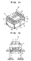
- Fig. 11 is an oblique view showing the structure of a transformer 10 in accordance with the seventh example which is seen from the bottom thereof, and Fig. 12 is a front view of the transformer 10, which is shown in Fig. 11 , mounted on a substrate.
- the junctions lie on lines along which the bobbin and core are joined with each other and at inner corners of the transformer.
- the positions to which the adhesive 4 used to secure the bobbin 2 and core 1 is applied correspond to the positions of the gaps, and lie on the surfaces of the primary winding and secondary winding along lines, along which the bobbin and core are joined with each other, at four inner corners of the transformer relative to the side of the transformer opposed to the substrate.
- the adhesive 4 is applied to the positions, a larger amount of adhesive 4 than the amount of adhesive employed in the aforesaid embodiment can be applied. Moreover, part of the adhesive 4 enters the gaps between the core 1 and bobbin 2. This provides the merit of providing sufficient strength of adhesive bonding.
- the core can be moved toward the secondary winding fixture or primary winding fixture.
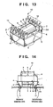
- Fig. 13 is an oblique view showing the structure of a transformer in accordance with the eighth example which is seen from the bottom thereof, and Fig. 14 is a front view of the structure of the transformer, which is shown in Fig. 13 , mounted on a substrate.
- the same reference numerals are assigned to the components that have already been described. The description of the components will be omitted and only a difference will be described.
- the core 1 is fixed to the bobbin 2, the core 1 is aligned with one side of the bobbin.
- the positions to which the affixing means 4 used to secure the bobbin 2 and core 1 is applied are, as shown in Figs. 13 and 14 , different between the primary winding and secondary winding.
- the positions relative to one winding to which the affixing means is applied are positions on the surface of the winding opposed to the core and joined with the bobbin which include at least two corners of the bobbin of the transformer.
- the positions relative to the other winding to which the affixing means is applied are positions along a line, along which the bobbin and core are joined with each other, at two inner corners out of four corners of the transformer defined by the other winding whose outer circumference is not secured. These positions are determined as a compromise of the positions relative to the primary winding and secondary winding to which the affixing means is applied according to the aforesaid embodiments.
- This example provides a means that proves more effective when a moment causing a breakdown and stemming from an impact of a drop is deflected.
- Fig. 15 is a front view showing the structure of a transformer in accordance with the ninth example.
- This example is characterized in that after the adhesive 4 used to secure the bobbin and core is applied in the same manner as that described in either of the aforesaid examples, the transformer is impregnated with a varnish 8, and the varnish 8 is then dried. Since the varnish 8 is dried at the temperature of about 120-C, the thermosetting adhesive remains hardened. This is advantageous.
- a transformer produced by assembling a winding member, which is made by winding a wound material about a bobbin, and a ferromagnetic core includes an affixing means for securing the bobbin and core which is applied relative to a primary winding and secondary winding.
- the affixing means is a thermosetting adhesive.
- the affixing means used to secure the bobbin and core and applied relative to the primary winding and secondary winding is applied to a plurality of positions on the surfaces of the windings opposed to the core and joined with the bobbin which include at least the four corners of the bobbin of the transformer or which lie on lines on the outer circumference of the transformer, along which the core and bobbin are joined/ with each other, and include at least the four corners of the bobbin of the transformer.
- the transformer need not be placed upside down in the process of manufacturing a transformer.
- adhesives can be applied readily and the production line can be automated.
- the affixing means used to secure the bobbin and core and applied relative to the primary winding and secondary winding is applied to a plurality of positions lying on lines, along which the bobbin and core are joined with each other, at four inner corners of the transformer when the transformer is seen from the side thereof opposite to the substrate.
- a larger amount of adhesive can therefore be applied.
- an adhesive can be readily poured into gaps between the core and bobbin, the higher and more stable strength of adhesive bonding can be provided.
- the affixing means used to secure the bobbin and core is applied to positions different between the primary winding and secondary winding.
- the positions relative to one winding to which the affixing means is applied are positions on the surface of the winding opposed to the core and joined with the bobbin which include at least two corners of the bobbin of the transformer or which lie on a line on the outer circumference of the transformer along which the core and bobbin are joined with each other and include at least two corners of the bobbin of the transformer.
- the positions relative the other winding to which the affixing means is applied are positions lying along a line, along which the bobbin and core are joined with each other, at two corners out of the four inner corners of the transformer, which are defined by the other winding that is not secured, along the line when the transformer is seen from the side thereof opposite to the substrate. Even when a moment causing a breakdown and imposed on the bobbin due to an impact of a drop is deflected, reinforcement can be achieved effectively.
- the core when the core is fixed to the bobbin, the core is aligned with one side of the transformer so that the affixing means can be applied to larger areas at positions on the surface of one winding opposed to the core and joined with the bobbin which include at least two corners of the bobbin of the transformer. Besides, the strength of adhesive bonding can be improved.
- the transformer After the affixing means used to secure the bobbin and core is applied, the transformer is impregnated with a varnish. Although a phenomenon that a transformer makes a sound at a natural frequency is likely to occur when the core is fixed to the bobbin using adhesives alone, the phenomenon will not take place. Moreover, since the varnish permeates through gaps between the core and bobbin, the core is affixed to the bobbin on a planar basis. The strength against a drop further improves.
- a transformer assembling method, a transformer, and a transformer-mounted substrate in which the anti-breakdown strength of a transformer can be improved, the performance of a ferrite core can be drawn out fully, and the transformer can be designed to be compact and lightweight.
- a transformer capable of resisting a drop and being produced according to the on-going process of manufacturing a transformer without the use of any special component or material.
- Fig. 18 is a partly broken diagram showing a transformer in accordance with the tenth example which is mounted on a substrate 20 and seen from the front side thereof.
- Fig. 19 is an enlarged sectional view of a major portion of the transformer shown in Fig. 18 .
- a bobbin is made of a given resin material by performing injection molding, and formed by uniting a winding member 2f, which has windings 3 of a primary winding and secondary winding and a bore formed thereon and therein, with a primary winding fixture and secondary winding fixture adjoining the openings of the bore.
- a ferromagnetic core 1 is divided into two portions and has a core portion thereof inserted into the bore.
- the ferromagnetic core also has an enclosure for enclosing the windings 3.
- Pedestals 2k of the bobbin 2 of the transformer 10 abut on a printed-circuit board 20 on which the transformer 10 is mounted.
- Lead pins 11 and 12 serving as terminals of the transformer 10 are inserted into holes 20b and secured with solder H.
- an insulating tape 7 is wound about the windings 3 of the winding member 2f of the bobbin 2.
- the whole transformer is then coated with a varnish 8 with which the whole transformer is impregnated.
- Gaps are created between the primary winding fixture and secondary winding fixture, which are coupled with the openings of the bore, and the top of the ferromagnetic core 1 and between the primary and secondary winding fixtures and the bottom of the ferromagnetic core 1.
- a silicon rubber 4sr of a given thickness is inserted into the gaps and secured by the varnish 8.
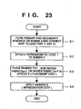
- step S1 in the flowchart describing the transformer assembling process of Fig. 23 lead wires are drawn out from the bobbin 2 of the transformer 10 having the primary and secondary windings, and, as shown in Figs. 18 and 19 , tangled about the lead pins 11 and 12 in order to thus connect the transformer to the printed-circuit board.
- the ferromagnetic core 1 is attached at step S2.
- the silicon rubber 4sr is placed in the gaps S between the bobbin 2 and ferromagnetic core 1 of the transformer 10.
- the whole transformer 10 is impregnated with the varnish 8 and thus hardened.
- the silicon rubber 4sr having a thickness corresponding to the height of the gaps S between the bobbin 2 and ferromagnetic material 1 is placed, the movement of the ferromagnetic core 1 relative to the bobbin 2 caused by a drop can be restrained. Eventually, the bobbin 2 can be prevented from cracking due to the movement of the ferromagnetic core 1 of the transformer caused by the drop.
- the transformer 10 mounted on the substrate 20 is resistive to a drop in any of X, Y, and Z directions, but especially to a drop in the Y direction.
- a movement in the Y direction of the ferromagnetic core 1 deriving from a drop in the Y direction of the transformer 10 can be restrained.
- a load with a moment M imposed on the pedestals 2k of the bobbin 2 due to the movement of the ferromagnetic core 1 can therefore be alleviated.
- a stress concentrated on the ridges on the borders between the pedestals 2k of the bobbin 2 and the side surfaces thereof due to an angular moment M exerted by the ferromagnetic core 1 with the impact of the drop can be dispersed.
- the bobbin can be prevented from cracking.
- the silicon rubber 4sr serves as an impact absorbent because of the soft material thereof.
- a tensile force is imposed on one pedestal 2k and a compression force is imposed on the other pedestal 2k. These forces are alleviated by the silicon rubber.
- the windings 3 of the transformer will therefore not be damaged and can be prevented from being disconnected.
- Fig. 21 is an enlarged view of a major portion shown in Fig. 18 in accordance with the tenth example.
- gaps S2 are created between the top 2a of the bobbin 2 of the transformer 10 and the bottom of the ferromagnetic core 1.
- a nonwoven fabric 5nf is placed in the gaps and used as an impregnation material through which the varnish 8 permeates.
- the nonwoven fabric 5nf is placed in the gaps between the bobbin 2 of the transformer 10 having the windings and the ferromagnetic core 1. Thereafter, the whole transformer 10 is impregnated with the varnish 8. The varnish 8 permeates through the nonwoven cloths 5nf existent on the tops 2a of the pedestals 2k of the bobbin 2 of the transformer 10 and on the bottom of the ferromagnetic core 1.
- the permeative varnish 8 is also poured into the gaps S1 under the bottom of the ferromagnetic core 1. After varnishing is completed, the transformer 10 is heated in order to harden the varnish 8.
- the nonwoven fabrics 5nf in the gaps under the ferromagnetic core 1 and impregnated with the varnish 8 can restrain the ferromagnetic core 1 from moving relative to the bobbin 2 with an impact of a drop while deforming in the direction of the thickness thereof.
- the nonwoven fabric 5nf impregnated with the varnish 8 serves as a proper impact absorbent to alleviate an impact of a drop. Consequently, the bobbin can be prevented from being cracking.
- the transformer 10 mounted on the substrate 20 is resistive to any drop irrespective of the direction of the drop and especially to a drop in the Y direction shown in Fig. 20 .
- the movement in the Y direction of the ferromagnetic core 1 deriving from an impact of a drop in the Y direction of the transformer 10 can be restrained, the impact imposed on the pedestals and side surfaces of the bobbin 2 due to the movement of the ferromagnetic core 1 can be alleviated.
- a drop test was conducted under the conditions that the transformer 10 was soldered to the substrate 20 and then stowed in a housing and the housing was dropped with each of six surfaces thereof facing downward. At that time, when the housing was dropped repeatedly from the height of a work desk (approximately 75 cm) three times, the bobbin cracked. According to the structure of this example, since the nonwoven fabric 5nf whose thickness is slightly smaller than the height of the gaps S between the bobbin 2 and ferromagnetic core 1 is employed, even after the drop was repeated seven times, the bobbin did not crack.
- the structure of this example can improve the anti-drop strength of the transformer 10.
- Fig. 22 is an enlarged view showing part of a side surface of a transformer in accordance with the eleventh.
- a woven fabric 6wf that is an isolating member is placed in the gaps S between the bobbin 2 and ferromagnetic core 1.
- the permeation of the varnish 8, which is an impregnation material, through the isolating member can be controlled by changing the size of each mesh of the fabric.
- the structures of the transformer 10 resistive to a drop in accordance with the examples are concerned with a transformer whose ferromagnetic core 1 is placed sideways.
- the structures can be adapted to a transformer whose ferromagnetic core 1 is placed lengthwise.
- the isolating member whose thickness nearly corresponds to the height of the spaces created between the bobbin and ferromagnetic core is placed in the spaces.
- the movement of the ferromagnetic core relative to the bobbin deriving from a drop can therefore be restrained.
- the bobbin can be prevented from cracking due to the movement of the ferromagnetic core of the transformer deriving from the impact of the drop.
- the proper impact absorbent is included.
- An impact of a drop can be alleviated for fear the windings of the transformer be damaged.
- the windings of the transformer can be prevented from being disconnected.
- the anti-drop strength of the transformer can be improved without a drastic change in the known transformer assembling process merely by adding an easy step and modifying the impregnation step that is the last step of the known transformer assembling. No special means such as an adhesive is therefore necessary. This is advantageous.
- a transformer assembling method, a transformer, and a transformer-mounted substrate in which the anti-breakdown strength of a transformer can be improved, the performance of a ferrite core can be drawn out fully, and the transformer can be designed to be compact and lightweight.
- Fig. 24 is an oblique view showing a transformer 10 in accordance with the twelfth example which is seen from the side of the transformer opposed to a substrate.
- Fig. 25 is an oblique view showing the transformer 10 mounted on the substrate 20.
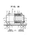
- Fig. 26 is an A-A sectional view of the transformer shown in Fig. 25 .
- a bobbin is made of a given resin material by performing injection molding, and formed by uniting a winding member 2f, which has primary and secondary windings 3 and a bore formed thereon and therein, with a primary winding fixture and secondary winding fixture adjoining the openings of the bore.
- a ferromagnetic core 1 is divided into two portions, and has the core portion thereof inserted into the bore.
- the ferromagnetic core also includes an enclosure for enclosing the windings 3.
- Pedestals 2k of the bobbin 2 of the transformer 10 abut directly on the surface of a printed-circuit board 20 on which the transformer 10 is mounted.
- Lead pins 11 and 12 serving as terminals of the transformer 10 are inserted into holes 20b of the substrate 20 and then secured using solder H.
- an insulating tape 7 is, as illustrated, wound about the windings 3 of the winding member of the bobbin 2.
- the whole transformer is impregnated with and coated with a varnish 8.
- Gaps are created between the primary winding fixture and secondary winding fixture coupled with the openings of the bore 2t and the top of the ferromagnetic core 1 and between the primary winding fixture and secondary winding fixture and the bottom of the ferromagnetic core 1.
- a hot-melt adhesive 15 (for example, adhesive Jet-Melt Nos. 3764, 3748, or 3797 manufactured by Sumitomo 3M Co., Ltd.) is applied to areas along lines, along which the bobbin 2 and core 1 are joined with each other, on the side of the transformer opposed to the substrate 20 and to areas on the margins of the isolating tape 7 wound about the outer circumferences of the windings 3.
- the hot-melt adhesive 15 is also applied to valleys between the outer circumference of the isolating tape 7 covering the windings 3 of the transformer 10 and surfaces 1b of the ferromagnetic core 1.
- the hot-melt adhesive 15 is thus used for affixing.
- the fixation between the bobbin 2 and ferromagnetic core 1 can be reinforced.
- the bobbin of the transformer 10 can be prevented from cracking due to an impact of a drop irrespective of the direction of the drop.
- the hot-melt adhesive 15 is, soft, it is effective in absorbing the impact of the drop. With the hot-melt adhesive, a proper impact absorbent can therefore formed. This is a very effective countermeasure against cracking of the bobbin.
- the hot-melt adhesive 15 is hardened at a room temperature immediately after it is jetted out of a heat gun. Unlike an epoxy adhesive made of a thermosetting resin, it does not take much time for the hot-melt adhesive to harden. This leads to good workability and each handling. The hot-melt adhesive is therefore optimal for mass-production.
- the hot-melt adhesive 15 has already been used at a step of firmly affixing a housing, or any other step in the process of producing a known electronic device. There is no problem in terms of safety.
- the varnish 8 is impregnated through the whole transformer 10 and hardened at the impregnation step.
- the varnish 8 is intended to prevent the transformer from making a sound. If sufficient strength of adhesive bonding is ensured, the varnish need not be employed.
- the transformer 10 mounted on the substrate 20 is, as shown in the oblique view of Fig. 25 , resistive to a drop in any of X, Y, and Z directions and especially to a drop in the Y direction. Since the movement in the Y direction of the ferromagnetic core 1 deriving from an impact of a drop in the Y direction of the transformer 10 can be restrained by applying the adhesive 15, a load with a moment M imposed on the pedestals 2k of the bobbin 2 due to the movement in the Y direction of the ferromagnetic core 1 can be alleviated.
- a stress concentrated on the ridges on the borders between the pedestals 2k of the bobbin 2 and the side surfaces thereof due to an angular moment M exerted by the ferromagnetic core 1 with the impact of the drop can be dispersed, whereby the bobbin can be prevented from cracking.
- the hot-melt adhesive 15 serves as a proper impact absorbent owing to the soft material thereof.
- the substrate 20 is dropped, if the angular moment M works, a tensile force is imposed on one pedestal 2k and a compression force is imposed on the other pedestal 2k.
- Fig. 27 is an oblique view showing the appearance of a transformer 10 in accordance with the thirteenth example.
- the same reference numerals are assigned to the components that have already been described. The description of the components will be omitted.
- the hot-meld adhesive 15 is, as illustrated, applied to areas linking the outer surfaces 2a of the primary winding fixture and secondary winding fixture and the outer surfaces 1a of the ferromagnetic core 1, and to four corners 15-1, 15-2, 15-3, and 15-4.
- Fig. 28 shows the appearance of a transformer 10 in accordance with the fourteenth example.
- the hot-melt adhesive 15 is applied to all areas along lines along which the tape 7 covering the bobbin on the side of the transformer opposed to the components-mounted surface of a substrate, and the bobbin 2 are joined with each other when the transformer is mounted o the substrate 20. Owing to the structure, the anti-impact strength of the transformer preventing the pedestals 2k of the bobbin 2 from cracking can be further improved.
- the countermeasure against a drop is concerned with a transformer whose ferromagnetic core is placed sideways.
- the countermeasure may be taken to protect a transformer whose ferromagnetic core is placed lengthwise.
- Figs. 29A to 29C are bottom views showing the transformers in accordance with the aforesaid examples which are seen from the sides thereof opposed to the components-mounted surface of a substrate.
- the hot-melt adhesive 15 is applied to valleys formed between the isolating tape 7 covering the outer circumferences of the windings and the surfaces 1b of the ferromagnetic core 1 and to areas linking the outer surfaces 2a of the primary winding fixture and secondary winding fixture and the outer surfaces 1a of the ferromagnetic core 1.
- the hot-melt adhesive 15 is applied to the four corners 15-1, 15-2, 15-3, and 15-4 formed among the isolating tape 7 covering the outer circumferences of the windings, the ferromagnetic core 1, and the surfaces of the primary winding fixture and secondary winding fixture which are opposed to each other, and to areas linking the outer surfaces 2a of the primary winding fixture and secondary winding fixture and the outer surfaces la of the ferromagnetic core 1.
- the hot-melt adhesive 15 is applied to valleys formed between the isolating tape 7 covering the outer circumferences of the windings and the ferromagnetic core 1, and to areas adjoining the valleys between the surfaces of the primary winding fixture and secondary winding fixture which are opposed to each other and the edges of the windings. Furthermore, the hot-melt adhesive 15 is applied to areas linking the outer surfaces of the primary winding fixture and secondary winding fixture and the outer surfaces of the ferromagnetic core.
- the fixation between the core and bobbin can be reinforced.
- the bobbin can be prevented from cracking due to the movement of the core of the transformer derived from an impact of a drop.
- the anti-drop strength of the transformer can be improved.
- the hot-melt adhesive 15 is soft, it is effective in absorbing the impact of the drop.
- the hot-melt adhesive is hardened immediately after applied, the workability of applying the hot-melt adhesive is good and the hot-melt adhesive can be handled easily. Since the hot-melt adhesive has already been used in the process of manufacturing a known electronic device, there is no problem in terms of safety.
- the fixation in the areas in which the core 1 and bobbin 2 are joined with each other can be reinforced.
- the movement of the transformer deriving from a drop can be restrained.
- the bobbin can be prevented from cracking due to the impact of the drop.
- the anti-drop strength of the transformer can be improved.
- the fixation in the areas linking the side surfaces of the core and bobbin can be reinforced, when an impact of a drop is imposed on the transformer especially in a lateral direction, the movement of the transformer deriving from the drop can be restrained effectively.
- the bobbin can therefore be prevented from cracking due to the movement of the core.
- the anti-drop strength of the transformer can be improved.
- the movement of the core of the transformer deriving from an impact of a drop can be restrained.
- the adhesive is applied to the four corners on the back of the core of the transformer, another component can be mounted adjacently to the transformer. This provides the freedom in designing a pattern for a substrate.
- the fixation between the bobbin and core can be further reinforced owing to the adhesion of the varnish.
- a thermoplastic adhesive is applied, the fixation between the core and bobbin can be further reinforced.
- the anti-drop strength of the transformer can be improved.
- the hot-melt adhesive is used to realize a proper impact absorbent. An impact of a drop is thus alleviated for fear the windings of the transformer be damaged too knowingly. The windings of the transformer can thus be prevented from being disconnected.
- the anti-drop strength of the transformer can be improved without a drastic change in the known transformer assembling process merely by adding a simple step of affixing.
- the application of the hot-melt adhesive 15 may be carried out as a countermeasure taken to protect a transformer from a drop after the step of varnishing.
- a transformer assembling method, a transformer, and a transformer-mounted substrate in which the anti-breakdown strength of a transformer can be improved, the performance of a ferrite core can be drawn out fully, and the transformer can be designed to be compact and lightweight.
- Fig. 30 is a plan view showing the structure of a transformer in accordance with the fifteenth example
- Fig. 31 is a front view of the structure shown in Fig. 30 .
- a transformer employed in a switching power supply unit comprises a core 1 made of a ferrite, a bobbin 2 about which a wound material is wound to form windings and which is made of a resin, and a winding member 3 that is a coil made by winding a wound material used to form windings, an inter-layer isolation tape, and a barrier tape used to space the primary and secondary windings in order to meet safety standards according to a given winding method.
- An adhesive 4 serving as an affixing means used to secure the bobbin 2 and core 1 is, as shown in Figs. 30 and 31 , applied to a total of four positions at the ends of the primary winding and secondary winding on the collars 2a of the bobbin 2.
- An epoxy adhesive that is a thermosetting adhesive is used as the adhesive 4.
- an adhesive 5 is applied to the junctions between members constituting the core 1.
- An adhesive 6 is applied to the junction between the upper end 2b of the bobbin 2 at the end of the secondary winding and the core 1.
- a moment M or an excessive impact is concentrated on the transformer, which is heavier than the other components of the power supply unit, in a direction of an arrow shown in Fig. 43 .
- the bobbin 2 fails to resist the moment or impact and is relatively readily ruptured near a portion thereof coupled to the winding member.
- a drop test was conducted as one of various drop tests on a transformer whose core 1 and bobbin 2 were not secured. Since the core 1 and bobbin 2 were not secured, the core 1 was thought to crack. As a result, the bobbin 2 cracked as shown in Fig. 43 . It was confirmed that the core 1 had sufficient anti-impact resistivity but the strength of the bobbin 2 was insufficient.
- the adhesive 4 used to secure the bobbin 2 and core 1 is, as shown in Figs. 30 and 31 , applied to the four positions at the ends of the primary and secondary windings.
- the strength of adhesive bonding between the bobbin 2 and core 1 is thus intensified, whereby a breaking force imposed on the bobbin 2 with a moment M or an impact derived from a drop is dispersed.
- a simple change should merely be made at a step of applying an adhesive in the process of manufacturing a transformer, that is, the number of positions to which an adhesive is applied should merely be increased. This provides the merit that no special means or material is needed. Another merit is that the strength of a transformer against a drop improves.
- an epoxy thermosetting adhesive is used as the affixing means used to secure the bobbin 2 and core 1.
- the strength of adhesive bonding will not be degraded by heat dissipated due to self-heating occurring when the transformer in a power supply unit is actuated.
- Fig. 32 is a top view showing the structure of a transformer in accordance with the sixteenth example of the present invention
- Fig. 33 is a side view of the structure.
- the sixteenth example provides the same structure as the fifteenth example.
- an affixing means 7 an used to secure the bobbin 2 and core 1 is, as shown in Figs. 32 and 33 , applied to areas at the ends of the primary winding and secondary winding, and is a thermosetting adhesive made of a silicon material.
- the silicon adhesive Compared with the epoxy adhesive, the silicon adhesive exhibits slightly low strength of adhesive bonding relative to the core. The silicon adhesive is therefore applied to wider areas.
- the adhesive 5 is, like the one employed in the fifteenth example, used to secure members constituting the core 1.
- the hardened silicon adhesive is softer than the normally-adopted epoxy adhesive that is hardened, and can be set to any hardness level.
- the cracking of the core or the peeling of the adhesive caused by a stress concentrated on the ferromagnetic core due to a cyclic change in temperature dependent on the use state of the transformer can be prevented (not shown because the structure is identical to the one shown in Fig. 30 ).
- the same coef f icient of linear expansion of the adhesive made of an epoxy material may be equalized with that of the ferromagnetic core, or an adhesive whose coefficient of linear expansion is approximated to a coefficient of linear expansion permitting prevention of cracking of the core deriving from a cyclic change in temperature dependent on the use state of the transformer may be employed.
- This makes it possible to prevent the cracking of the core or the peeling of the adhesives caused by a stress concentrated on the ferromagnetic core due to the cyclic change in temperature dependent on the use state of the transformer.
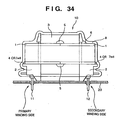
- Fig. 34 is a front view of a transformer in accordance with the seventeenth example of the present invention.
- thermosetting adhesives 4 and 7ad used to secure the bobbin 2 and core 1 are, as shown in Fig. 7 , applied to areas at the ends of the primary winding and secondary winding, and are thermosetting adhesives.
- the thermosetting adhesives may be made of either an epoxy material or silicon material.
- the transformer is impregnated with the varnish 8.
- the varnish 8 is then dried. Since the varnish 8 is dried at the temperature of about 120EC, the thermosetting adhesives remain hardened. This is advantageous.
- An adhesive made of an incombustible material may be used as the adhesives employed in the aforesaid cases.
- a transformer using such an adhesive can be adopted not only for a mere DC-to-DC converter but also for a converter included in a switching power supply requested to meet safety standards.
- the use of the adhesive made of an incombustible material also has the merit that the safety of the transformer improves.
- the transformer 10 having the foregoing structure was dropped off a desktop (approximately 75 cm high) to a floor seven times in the same direction. Nevertheless, the transformer was not ruptured.
- the epoxy adhesive serving as the affixing means used to secure the bobbin 2 and core 1 is a thermosetting adhesive. Natural hardening is facilitated by heat dissipated due to self-heating occurring when the transformer in a power supply unit is actuated. Moreover, since the adhesive exhibits good thermal conductivity, the strength of adhesive bonding of the adhesive will, unlike that of a thermoplastic adhesive, not be degraded.
- the adhesives 4 and 7ad are used for fixation, a phenomenon that a transformer makes a sound at a natural frequency and is likely to occur will not take place. Besides, the varnish permeates through the gaps between the core and bobbin. The core and bobbin are therefore affixed to each other on a planar basis. This provides the merit that the anti-drop strength of the transformer further improves.
- a transformer assembling method, a transformer, and a transformer-mounted substrate in which the anti-breakdown strength of a transformer can be improved, the performance of a ferrite core can be drawn out fully, and the transformer can be designed to be compact and lightweight.
- a transformer capable of resisting a drop and being produced in the on-going process of manufacturing a transformer without the use of any special component or material.
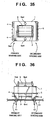
- Fig. 35 is a plan view showing the structure of a transformer in accordance with the eighteenth example
- Fig. 36 is a front view of the structure shown in Fig. 35 .
- a transformer employed in a switching power supply unit is, as illustrated, composed of a core 1 made of a ferrite, a bobbin about which a wound material is wound to form windings and which is made of a resin, and a winding member 3 made by winding the wound material used to form the windings, an inter-layer isolation tape, a barrier tape used to space the primary and secondary windings in order to meet safety standards, according to a given winding method.
- the transformer is soldered and fixed to the substrate 20 with pins therefore inserted through holes bored in the substrate.
- the adhesive 4 serving as an affixing means used to secure the bobbin 2 and core 1 is, as shown in Figs. 35 and 36 , applied to positions at the ends of the primary winding and secondary winding on the collars of the bobbin 2.
- An epoxy thermosetting adhesive is used as the adhesive 4.
- the first adhesive and second adhesive used to secure the bobbin 2 and core 1 are the adhesive 4 applied to the primary winding fixture and the adhesive 5 applied to the secondary winding fixture.
- a thermosetting epoxy adhesive is used as the adhesive 4 applied to the primary winding.
- the adhesive 5ad applied to the secondary winding fixture is a thermosetting silicon adhesive.
- the hardened adhesive 4 is harder than the hardened adhesive 5ad.
- the strength of adhesive bonding between the ferromagnetic core 1 and bobbin 2 which is exerted by the silicon adhesive is little lower than that exerted by the epoxy adhesive.
- the silicon adhesive is therefore applied to wider areas.
- the adhesive 6ad is used to secure members constituting the ferromagnetic core 1.
- the adhesive 7ad is an adhesive that has customarily been used to secure the ferromagnetic core 1 and bobbin 2 in the past. According to the present invention, the adhesive is not a must.
- a moment M or an excessive impact is concentrated on the transformer, which is heavier than the other components of the power supply unit, in a direction of an arrow shown in Fig. 43 .
- the bobbin 2 fails to resist the moment or impact and is relatively readily ruptured near a portion thereof coupled with the winding member.
- a drop test was conducted as one of various drop tests on a transformer whose core 1 and bobbin 2 were not secured. Since the core 1 and bobbin 2 were not secured, the core 1 was thought to crack. However, a crack occurred at the position shown in Fig. 43 . This demonstrated that the anti-impact resistivity of the ferromagnetic core 1 was sufficient but the strength of the bobbin 2 made of a resin material was insufficient.
- the adhesives 4 and 5ad used to secure the bobbin 2 and core 1 are, as shown in Figs. 35 and 36 , applied to areas at the ends of the primary winding and secondary winding.
- a drop test was conducted on the transformer having the bobbin 2 and core 1 secured in this way, the strength of adhesive bonding between the bobbin 2 and core 1 was apparently intensified.
- a breaking force was dispersed by distributing an moment M or impact deriving from a drop to the bobbin 2 and ferromagnetic core 1. Owing to the illustrated structure, the transformer becomes strong enough not to break down with a drop.
- the adhesives 4 and 5ad employed have different hardness levels. Specifically, the silicon adhesive 5ad that is softer is used to alleviate (absorb) a stress stemming from a difference in coefficient of linear expansion between the bobbin 2 and core 1. Occurrence of a crack of the core deriving from expansion or contraction due to a cyclic change in temperature can be prevented.
- an epoxy adhesive and silicon adhesive used as the adhesives to secure the bobbin 2 and core 1 are of a thermosetting type.
- the adhesives are hardened with heat dissipated due to self-heating occurring when the transformer in a power supply unit is actuated. It will therefore not take place that the strength of adhesive bonding deteriorates because of softening. For this reason, the employment of the adhesives is preferable. Moreover, it is also preferable in terms of use practice.
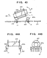
- Fig. 37 is an oblique view showing a transformer in accordance with the nineteenth example of the present invention which is seen from the bottom thereof, and Fig. 38 is a front view of the transformer.
- the adhesive 6ad is used to secure members constituting the ferromagnetic core 1.
- the adhesive 7ad is an adhesive used to secure the core 1 and bobbin 2 and has no direct relation to the present invention (this does not mean that the adhesive 7ad does not act as a reinforcement).
- the adhesive 5ad applied to the secondary winding fixture in order to secure the bobbin 1 and core 2 is a thermosetting silicon adhesive.
- an adhesive 8ad applied to the secondary winding fixture in order to secure the bobbin 2 and ferromagnetic core 1 is a thermoplastic hot-melt adhesive.
- the adhesive 8ad is, for example, an adhesive called Jet Melt No. 3748 and manufactured by Sumitomo 3M Co., Ltd. Since the adhesive 8ad is a thermoplastic adhesive, it is moderately soft and can therefore alleviate an impact deriving from a drop.
- the adhesive 8ad is, as illustrated, applied to junctions between the bobbin 2 and one winding 3 so that the adhesive will face the components-mounted surface of a substrate.
- Fig. 39 is a plan view showing the structure of a transformer in accordance with the twentieth example
- Fig. 40 is a front view showing the structure of the transformer mounted on a substrate.
- the adhesive 4 applied to the primary winding fixture is, as shown in Figs. 39 and 40 , a thermosetting epoxy adhesive.
- a varnish 8 with which the transformer is impregnated is used as an affixing means to be applied to the secondary winding fixture.
- the density of the varnish 8 employed is adjusted and managed so that the varnish can permeate through the gaps between the bobbin 2 and ferromagnetic core 1 and a certain amount of varnish can adhere to the bobbin and core.
- a countermeasure against a drop can be taken, and the fear that the core may crack because of a difference in coefficient of linear expansion will be eliminated.
- the varnish 8 permeates through the gaps between the core 1 and bobbin 2.
- the core and bobbin are therefore affixed to each other on a planar basis.
- Fig. 41 is an oblique view showing a transformer in accordance with the twenty-first example which is seen from the bottom thereof, and Fig. 42 is a front view showing the structure.
- the adhesive 4 applied to the primary winding fixture is a thermosetting epoxy adhesive.
- the varnish 8 with which the transformer is impregnated is used as an affixing means to be applied to the secondary winding fixture.
- the hot-melt adhesive 8ad that is a thermoplastic adhesive is applied to the varnish 8 and then solidified.
- the adhesive 8ad that is a hot-melt adhesive (for example, Jet Melt No. 3748 manufactured by Sumitomo 3M Co., Ltd.) is applied to a portion of the transformer that is not secured with the epoxy adhesive.
- a hot-melt adhesive for example, Jet Melt No. 3748 manufactured by Sumitomo 3M Co., Ltd.
- the transformer having the foregoing structure was dropped off a desktop (approximately 75 cm high) to a floor seven times in the same direction. Nevertheless, the transformer was not ruptured.
- the structure has the merit that sufficient strength of adhesive bonding can be exerted.
- the aforesaid examples are concerned with a transformer whose core is placed sideways.
- the present invention can apply to a transformer whose core is placed lengthwise.
- the primary winding fixture and secondary winding fixture to which the adhesives 4 and 5ad are applied may be switched. The same advantage can still be provided.
- the structure may be adapted to the known transformers described in conjunction with Figs. 47 and 48 .
- the same advantage can still be provided.
- the adhesive applied to the primary winding fixture and the adhesive applied to the secondary winding fixture have mutually different hardness levels.
- the bobbin can therefore be prevented from cracking due to a cyclic change in temperature of the transformer occurring when the transformer is actuated for power supply.
- the core can be fixed to the bobbin on both sides of the transformer. The transformer can therefore exert sufficient anti-drop strength.
- the adhesives having mutually different hardness levels are thermosetting adhesives.
- the adhesives can be hardened at the same step.
- one of the adhesives having mutually different hardness levels is an epoxy adhesive widely adopted, and the other adhesive is a silicon adhesive widely adopted.
- the adhesives are therefore readily available. This leads to the merit that great freedom is ensured in selection of adhesives meeting the safety standards for a power transformer, for example, the standard of the UL standards stipulating an incombustible material.
- one of the adhesives having mutually different hardness levels is a thermosetting epoxy adhesive and the other adhesive is a thermoplastic hot-melt adhesive.
- the adhesives can be, if necessary, applied afterward to a transformer purchased as a normal component in the assembling process for a power supply. There is therefore the merit that an existing transformer can be used as it is.
- the hot-melt adhesive is made of a material that has been employed in the past.
- the adhesive can be used readily with safe in the course of a production line.
- one of the adhesives having mutually different hardness levels is an epoxy adhesive and the other is the varnish with which the transformer is impregnated and which serves as an affixing means.
- the varnish permeates through the gaps between the core and bobbin, the core and bobbin are affixed to each other on a planar basis.
- the hot-melt adhesive is applied to a portion of the transformer which is not secured with the epoxy adhesive. This provides the merit that the anti-drop strength of the transformer is further intensified.
- a transformer assembling method, a transformer, and a transformer-mounted substrate in which the anti-breakdown strength of a transformer can be improved while the strength thereof against a drop is intensified, the performance of a ferrite core can be drawn out fully, the transformer can be designed to be compact and lightweight, and the core of the transformer can be protected from cracking due to a cyclic change in temperature of the transformer occurring when the transformer is actuated for power supply.
Claims (45)
- Transformator-Zusammenbauverfahren zum Herstellen eines Transformators (10) durch Zusammensetzen einer Spule (2), die gebildet ist durch Vereinen eines Wicklungselements (2f, 3) mit einer Primärwicklung und einer Sekundärwicklung und einer daran und darin ausgebildeten Bohrung, mit einer Primärwicklungsfixierung und einer Sekundärwicklungsfixierung in der Nachbarschaft der Öffnungen der Bohrung, und eines ferromagnetischen Kerns (1), der mit einem Kernteil in die Bohrung eingesetzt ist und eine Umschließung zum Umschließen der Wicklungen aufweist, umfassend:einen Fixierungsschritt zum Fixieren der Primärwicklungsfixierung und/oder der Sekundärwicklungsfixierung an dem ferromagnetischen Kern (1), wobei bei dem Fixierungsschritt ein wärmehärtbarer Klebstoff verwendet wird,dadurch gekennzeichnet, dass
bei dem Fixierungsschritt der wärmehärtbare Klebstoff (4) aufgetragen wird auf mehrere Zonen, die zwischen Bünden (2a) der Primärwicklungsfixierung und der Sekundärwicklungsfixierung und Oberflächen des ferromagnetischen Kerns (1) parallel zu den Öffnungen der Bohrung liegen, oder
bei dem Fixierungsschritt der wärmehärtbare Klebstoff (4) aufgetragen wird auf mehrere Zonen, die zwischen den Seitenflächen (2c) der Primär- und Sekundärwicklungsfixierung in Längsrichtung der Bohrung und den Seitenflächen des ferromagnetischen Kerns (1) in Längsrichtung der Bohrung befinden, oder
bei dem Fixierungsschritt der wärmehärtbare Klebstoff (4) aufgetragen wird auf mehrere Zonen, die zwischen den einander gegenüberliegenden Innenflächen (2d) der Primär- und Sekundärwicklungsfixierung und dem Boden des ferromagnetischen Kerns (1) gegenüber einem Substrat (20) liegen, wenn der Transformator (10) auf dem Substrat (20) angebracht wird, oder
bei dem Fixierungsschritt der ferromagnetische Kern (1) in Richtung der Sekundärwicklungsfixierung oder der Primärwicklungsfixierung bewegt wird und dann der wärmehärtbare Klebstoff aufgetragen wird auf Zonen, die gebildet sind zwischen der Innenfläche (2d) der Sekundärwicklungsfixierung und dem Boden des ferromagnetischen Kerns (1) gegenüber einem Substrat (20), wenn der Transformator (10) auf dem Substrat (20) angebracht wird, sowie aufgetragen wird auf eine Zone, die zwischen einem Bund (2a) der Primärwicklungsfixierung und einer Oberfläche des ferromagnetischen Kerns (1) parallel zu der Öffnung der Bohrung gebildet ist. - Transformator-Zusammenbauverfahren zum Herstellen eines Transformators (10) durch Zusammensetzen einer Spule (2), die gebildet ist durch Vereinen eines Wicklungselements (2f, 3) mit einer Primärwicklung und einer Sekundärwicklung und einer daran und darin ausgebildeten Bohrung, mit einer Primärwicklungsfixierung und einer Sekundärwicklungsfixierung in der Nachbarschaft der Öffnungen der Bohrung, und eines ferromagnetischen Kerns (1), der mit einem Kernteil in die Bohrung eingesetzt ist und eine Umschließung zum Umschließen der Wicklungen aufweist, umfassend:einen Fixierungsschritt zum Fixieren der Primärwicklungsfixierung und/oder der Sekundärwicklungsfixierung an dem ferromagnetischen Kern (1),dadurch gekennzeichnet, dass
der Fixierungsschritt außerdem umfasst die Verwendung eines thermoplastischen Klebstoffs (15), welcher auf den Außenumfängen der Wicklungen (3) gegenüber der mit den Komponenten bestückten Oberfläche eines Substrats (20) aufgetragen wird. - Verfahren nach Anspruch 2,
bei dem als thermoplastischer Klebstoff ein Heißschmelzklebstoff (15) mit einem aus einem Polypropylenharz hergestellten Klebstoff verwendet wird. - Verfahren nach Anspruch 2,
bei dem bei dem Fixierungsschritt der thermoplastische Klebstoff (15) aufgebracht wird auf Täler, die zwischen den Außenumfängen der Wicklungen und dem ferromagnetischen Kern (1) gebildet sind, und auf Zonen, welche die Außenflächen (2a) der Primärwicklungsfixierung und der Sekundärwicklungsfixierung mit den Außenflächen (1a) des ferromagnetischen Kerns (1) verbinden. - Verfahren nach Anspruch 2,
bei dem bei dem Fixierungsschritt der thermoplastische Klebstoff (15) aufgetragen wird auf vier Ecken (15-1, 15-2, 15-3, 15-4), die unter den Außenumfängen der Wicklungen, dem ferromagnetischen Kern (1) und den einander gegenüberliegenden Innenflächen (2d) der Primär- und der Sekundärwicklungsfixierung gebildet sind, und aufgebracht wird auf Zonen, welche die Außenflächen (2a) der Primär- und der Sekundärwicklungsfixierung mit den Außenflächen (1a) des ferromagnetischen Kerns (1) verbinden. - Verfahren nach Anspruch 4,
bei dem bei dem Fixierungsschritt der thermoplastische Klebstoff aufgetragen wird auf Zonen, welche die Täler zwischen den Innenflächen (2d) der einander gegenüberliegenden Primär- und
Sekundärwicklungsfixierung mit den Außenumfängen der Wicklungen verbinden. - Verfahren nach Anspruch 1,
bei dem der wärmehärtbare Klebstoff ein Epoxyklebstoff ist. - Verfahren nach Anspruch 7,
bei dem der lineare Ausdehnungskoeffizient des Epoxyklebstoffs ausgeglichen ist mit demjenigen des ferromagnetischen Kerns (1) oder auf einen linearen Ausdehnungskoeffizienten eingestellt ist, der es zu verhindern ermöglicht, dass der Kern (1) aufgrund einer zyklischen Temperaturänderung abhängig vom Benutzungszustand des Transformators (10) bricht. - Verfahren nach Anspruch 1,
bei dem der wärmehärtbare Klebstoff ein Siliconklebstoff ist. - Verfahren nach Anspruch 1,
bei dem der wärmehärtbare Klebstoff ein nicht brennbarer Klebstoff ist. - Verfahren nach einem der vorhergehenden Ansprüche,
weiterhin umfassend einen Imprägnierungsschritt zum Imprägnieren des Transformators (10) mit einem Imprägniermittel wie beispielsweise einem Firnis (8), nachdem der Fixierungsschritt abgeschlossen ist. - Verfahren nach Anspruch 1,
bei dem bei dem Fixierungsschritt zum Fixieren des ferromagnetischen Kerns (1) an der Primär- und der Sekundärwicklungsfixierung ein erster Klebstoff und ein zweiter Klebstoff mit unterschiedlichen Härtewerten verwendet werden. - Verfahren nach Anspruch 12,
bei dem der erste Klebstoff und der zweite Klebstoff wärmehärtbare Klebstoffe sind. - Verfahren nach Anspruch 13,
bei dem der erste Klebstoff ein Epoxyklebstoff ist, und der zweite Klebstoff ein Siliconklebstoff. - Verfahren nach Anspruch 13,
bei dem der erste Klebstoff ein wärmehärtbarer Klebstoff ist, und der zweite Klebstoff ein thermoplastischer Klebstoff. - Verfahren nach Anspruch 13,
bei dem der wärmehärtbare Klebstoff ein Epoxyklebstoff ist, und der thermoplastische Klebstoff ein Heißschmelzklebstoff. - Verfahren nach Anspruch 13,
bei dem der erste Klebstoff ein Epoxyklebstoff ist und ein Firnis (8), mit dem der Transformator (10) imprägniert wird, als der zweite Klebstoff verwendet wird. - Verfahren nach Anspruch 17,
bei dem ein Heißschmelzklebstoff aufgetragen wird auf jene Primärwicklungsfixierung oder Sekundärwicklungsfixierung, welche nicht unter Verwendung des Epoxyklebstoffs nach Abschluss der Imprägnierung fixiert ist. - Transformator (10), umfassend eine Spule (2), gebildet durch Vereinen eines Wicklungselements (3), welches eine Primärwicklung und eine Sekundärwicklung und eine daran und darin ausgebildete Bohrung aufweist, wobei eine Primärwicklungsfixierung und eine Sekundärwicklungsfixierung an die Öffnungen der Bohrung angrenzen, und ein ferromagnetischer Kern (1) mit einem Kernteil in die Bohrung eingesetzt ist, und mit einer Umschließung zum Umschließen der Wicklungen, wobei entweder die Primärwicklungsfixierung oder die Sekundärwicklungsfixierung oder beide Befestigungen an dem ferromagnetischen Kern (1) befestigt sind, wobei zum Befestigen ein wärmehärtbarer Klebstoff verwendet ist,
dadurch gekennzeichnet, dass
der wärmehärtbare Klebstoff (4) aufgetragen ist auf mehrere Zonen, die zwischen Bünden (2a) der Primärwicklungsfixierung und der Sekundärwicklungsfixierung und den Oberflächen des ferromagnetischen Kerns (1) parallel zu den Öffnungen der Bohrung gebildet sind, oder
der wärmehärtbare Klebstoff (4) aufgetragen ist auf mehrere Zonen, die zwischen den Seitenflächen (2c) der Primärwicklungsfixierung und der Sekundärwicklungsfixierung in Längsrichtung der Bohrung und den in Längsrichtung der Bohrung verlaufenden Seitenflächen des ferromagnetischen Kerns (1) gebildet sind, oder
der ferromagnetische Kern (1) in Richtung der Sekundärwicklungsfixierung oder der Primärwicklungsfixierung bewegt wurde und dann der hitzehärtbare Klebstoff (4) aufgetragen wurde auf Zonen, die zwischen der Innenfläche (2d) der Sekundärwicklungsfixierung und dem Boden des ferromagnetischen Kerns (1) gegenüber einem Substrat (20), wenn der Transformator (10) an dem Substrat (20) gelagert ist, gebildet sind, oder
der wärmehärtbare Klebstoff aufgebracht ist auf mehrere Zonen, die gebildet sind zwischen den einander gegenüberliegenden Innenflächen (2d) der Primär- und der Sekundärwicklungsfixierung, und dem Boden des ferromagnetischen Kerns (1) gegenüber einem Substrat (20), wenn der Transformator (10) an dem Substrat (20) gelagert ist, sowie auf eine Zone, die gebildet ist zwischen einem Bund (2a) der Primärwicklungsfixierung und einer parallel zur Öffnung der Bohrung verlaufenden Fläche des ferromagnetischen Kerns (1). - Transformator nach Anspruch 19,
bei dem der wärmehärtbare Klebstoff ein Epoxyklebstoff ist. - Transformator nach Anspruch 20,
bei dem der lineare Ausdehnungskoeffizient des Epoxyklebstoffs sich ausgleicht mit demjenigen des ferromagnetischen Kerns (1) oder auf einen linearen Ausdehnungskoeffizienten eingestellt ist, der es zu verhindern ermöglicht, dass der Kern (1) aufgrund einer zyklischen Temperaturänderung abhängig vom Benutzungszustand des Transformators (10) bricht. - Transformator nach Anspruch 19,
bei dem der wärmehärtbare Klebstoff ein Siliconklebstoff ist. - Transformator nach Anspruch 19,
bei dem wärmehärtbare Klebstoff ein nicht brennbarer Klebstoff ist. - Transformator (10), umfassend eine Spule (2), gebildet durch Vereinen eines Wicklungselements (3), welches eine Primärwicklung und eine Sekundärwicklung und eine daran und darin ausgebildete Bohrung aufweist, wobei eine Primärwicklungsfixierung und eine Sekundärwicklungsfixierung an die Öffnungen der Bohrung angrenzen, und ein ferromagnetischer Kern (1) mit einem Kernteil in die Bohrung eingesetzt ist, und mit einer Umschließung zum Umschließen der Wicklungen, wobei entweder die Primärwicklungsfixierung oder die Sekundärwicklungsfixierung oder beide Befestigungen an dem ferromagnetischen Kern (1) befestigt sind,
dadurch gekennzeichnet, dass
ein thermoplastischer Klebstoff (15) auf die Außenumfänge der Wicklungen gegenüber der mit Komponenten bestückten Oberfläche eines Substrats (20) aufgetragen ist. - Transformator nach Anspruch 24,
bei dem als thermoplastischer Klebstoff ein Heißschmelzklebstoff (15) mit einem aus einem Polypropylenharz hergestellten Klebstoff verwendet wird. - Transformator nach Anspruch 24,
bei dem der thermoplastische Klebstoff (15) aufgebracht ist auf Täler, die zwischen den Außenumfängen der Wicklungen und dem ferromagnetischen Kern (1) gebildet sind, und auf Zonen, welche die Außenflächen (2a) der Primärwicklungsfixierung und der Sekundärwicklungsfixierung mit den Außenflächen (1 a) des ferromagnetischen Kerns (1) verbinden. - Transformator nach Anspruch 24,
bei dem der thermoplastische Klebstoff (15) aufgebracht ist auf vier Ecken (15-1, 15-2, 15-3, 15-4), die unter den Außenumfängen der Wicklungen, dem ferromagnetischen Kern (1) und den einander gegenüberliegenden Innenflächen (2d) der Primär- und der Sekundärwicklungsfixierung, die gebildet sind, und aufgebracht wird auf Zonen, welche die Außenflächen (2a) der Primär- und der Sekundärwicklungsfixierung mit den Außenflächen (1a) des ferromagnetischen Kerns (1) verbinden. - Transformator nach Anspruch 26,
bei dem der thermoplastische Klebstoff aufgebracht ist auf Zonen, welche die Täler zwischen den einander gegenüberliegenden Innenflächen (2d) der Primär- und Sekundärwicklungsfixierung mit den Außenumfängen der Wicklungen verbinden. - Transformator nach einem der Ansprüche 19 bis 28,
bei dem der Transformator (10) mit einem Imprägnierungsmittel wie beispielsweise einem Firnis (8) imprägniert ist. - Transformator nach Anspruch 19,
dadurch gekennzeichnet, dass
ein erster Klebstoff und ein zweiter Klebstoff mit voneinander verschiedenen Härtewerten dazu benutzt sind, den ferromagnetischen Kern (1) an der Primärwicklungsfixierung und der Sekundärwicklungsfixierung zu befestigen. - Transformator nach Anspruch 30,
bei dem der erste und der zweite Klebstoff wärmehärtbare Klebstoffe sind. - Transformator nach Anspruch 31,
bei dem der erste Klebstoff ein Epoxyklebstoff ist, und der zweite Klebstoff ein Siliconklebstoff. - Transformator nach Anspruch 32,
bei dem der erste Klebstoff ein wärmehärtbarer Klebstoff ist, und der zweite Klebstoff ein thermoplastischer Klebstoff. - Transformator nach Anspruch 33,
bei dem der wärmehärtbare Klebstoff ein Epoxyklebstoff ist, und der thermoplastische Klebstoff ein Heißschmelzklebstoff. - Transformator nach Anspruch 32,
bei dem der erste Klebstoff ein Epoxyklebstoff ist und als zweiter Klebstoff ein Firnis (8) verwendet ist, mit dem der Transformator imprägniert ist. - Transformator nach Anspruch 35,
bei dem ein Heißschmelzklebstoff aufgebracht ist auf jene Primärwicklungsfixierung oder Sekundärwicklungsfixierung, welche nicht mit Hilfe des Epoxyklebstoffs nach Abschluss der Imprägnierung gesichert wurde. - Mit einem Transformator bestücktes Substrat, mit einem Substrat (20), auf dem ein Transformator (10) nach einem der Ansprüche 19 bis 36 angebracht ist.
- Stromversorgungseinheit mit einem mit Komponenten bestückten Substrat (20), auf dem ein Transformator (10) nach einem der Ansprüche 19 bis 36 angebracht ist, umfassend:eine Behältereinrichtung (13, 14) mit Sicherungsgliedern (13a, 14a) zum Immobilisieren und Sichern des mit Komponenten bestückten Substrats (20) in einer Richtung parallel zu der mit Komponenten bestückten Oberfläche des mit Komponenten bestückten Substrats (20), undintegrale Rückhalteglieder (13b, 14b), die einstückig mit der Behältereinrichtung (13, 14) ausgebildet sind, um eine Stoßkraft aufzunehmen, wenn eine Stoßbelastung in einer Richtung etwa orthogonal zu der mit Komponenten bestückten Oberflächen einwirkt,und/oder Rückhalteglieder (11, 12, 22a, 22b, 23a, 23b), die Teil des mit Komponenten bestückten Substrats (20) oder des Transformators (10) sind, um eine Stoßkraft aufzunehmen, wenn die Stoßbelastung in einer Richtung etwa orthogonal zu der mit Komponenten bestückten Oberfläche einwirkt, so dass das mit Komponenten bestückte Substrat (20) verlagert werden und einen Stoß absorbieren kann, und eine Verlagerung einschränken kann, deren Ausmaß gleich oder größer ist als ein gegebenes Ausmaß, um die Last zu verteilen.
- Einheit nach Anspruch 38,
bei der die Behältereinrichtung (13, 14) sich zusammensetzt aus einem Obergehäuse (13) und einem Untergehäuse (14), welche bei dazwischenliegendem Substrat (20) nach oben und nach unten voneinander abrückbar sind, wobei die Sicherungsglieder (13a, 14a) sich von dem Obergehäuse (13) und dem Untergehäuse (14) aus erstrecken, die Rückhalteglieder (13b, 14b) ausgebildet sind als Trägerglieder, die sich von dem Obergehäuse (13) und dem Untergehäuse (14) derart erstrecken, dass die Rückhalteglieder (13b, 14b) von dem mit Komponenten bestückten Substrat (20) abgerückt werden können um ein Stück, welches dem gegebenen Ausmaß entspricht, um in die den Transformator (10) umfassenden Bestückungskomponenten einzudringen. - Einheit nach Anspruch 38,
bei der die Behältereinrichtung (13, 14) sich zusammensetzt aus einem Obergehäuse (13) und einem Untergehäuse (14), welche bei dazwischenliegendem Substrat (20) nach oben und nach unten voneinander abrückbar sind, wobei die Sicherungsglieder (1 3a, 14a) sich von dem Obergehäuse (13) und dem Untergehäuse (14) aus erstrecken, und die Rückhalteglieder (13b, 14b) realisiert sind durch Belassen einer Distanz entsprechend dem gegebenen Ausmaß zwischen den Innenflächen des Obergehäuses (13) und des Untergehäuses (14), und den Enden der Bestückungskomponenten sowie den Enden von Leitungen zum Anbringen der Komponenten. - Einheit nach Anspruch 40,
bei der Abstrahlplatten (22, 23) sich unter den Bestückungskomponenten befinden. - Einheit nach einem der Ansprüche 38 bis 41,
bei der Dummy-Stege, die mit einem Druckmuster zu vereinen oder von diesem zu trennen sind, an dem mit Komponenten bestückten Substrat (20) ausgebildet sind, und die Festigkeit der Oberfläche des Substrats (20) verstärkt ist durch Beschichten der Oberfläche mit Lot während des Zufließens und Abfließens, um die Steifigkeit zu erhöhen. - Aufzeichnungsvorrichtung mit einer Stromversorgungseinheit nach einem der Ansprüche 38 bis 42,
umfassend eine Verbindungseinrichtung (30), die es ermöglicht, die Behältereinrichtung (13, 14) frei an einen Stromversorgungsstauraum (56) der Aufzeichnungsvorrichtung anzubringen oder daraus zu lösen, und außerdem dazu dient, die Behältereinrichtung (13, 14) mechanisch und elektrisch zu verbinden. - Vorrichtung nach Anspruch 43,
bei der die Aufzeichnungsvorrichtung einen Tintenstrahlaufzeichnungskopf aufweist, um Tinte zum Aufzeichnen auszustoßen, und einen Wechselstromadapter oder eine Stromversorgung in einem Einheitskörper zur Verwendung durch einen Benutzer aufweist. - Vorrichtung nach Anspruch 44,
bei der der Aufzeichnungskopf ein solcher zum Ausstoßen von Tinte mittels Wärmeenergie ist und versehen ist mit einem Thermowandler, mit dem Wärmeenergie zur Einwirkung auf die Tinte erzeugt wird.
Priority Applications (1)
| Application Number | Priority Date | Filing Date | Title |
|---|---|---|---|
| EP02014653A EP1253605B1 (de) | 1997-02-18 | 1998-02-12 | Stromversorgungseinheit mit auf einem Substrat montierten Transformator und Aufzeichnungsgerät mit Stromversorgungseinheit |
Applications Claiming Priority (12)
| Application Number | Priority Date | Filing Date | Title |
|---|---|---|---|
| JP9033834A JPH10229019A (ja) | 1997-02-18 | 1997-02-18 | トランス組立方法とトランスおよびトランス実装基板 |
| JP33834/97 | 1997-02-18 | ||
| JP3383397A JPH10229025A (ja) | 1997-02-18 | 1997-02-18 | トランス組立方法とトランスおよびトランス実装回路基板 |
| JP33833/97 | 1997-02-18 | ||
| JP43872/97 | 1997-02-27 | ||
| JP9043871A JPH10241953A (ja) | 1997-02-27 | 1997-02-27 | トランス組立方法とトランスおよびトランス実装基板 |
| JP43871/97 | 1997-02-27 | ||
| JP9043872A JPH10241954A (ja) | 1997-02-27 | 1997-02-27 | トランス組立方法とトランスおよびトランス実装基板 |
| JP43873/97 | 1997-02-27 | ||
| JP04387397A JP3524314B2 (ja) | 1997-02-27 | 1997-02-27 | トランス組立方法とトランスおよびトランス実装基板 |
| JP181598A JPH11204958A (ja) | 1998-01-07 | 1998-01-07 | 電源装置及び該電源装置を用いた記録装置 |
| JP1815/98 | 1998-01-07 |
Related Child Applications (1)
| Application Number | Title | Priority Date | Filing Date |
|---|---|---|---|
| EP02014653A Division EP1253605B1 (de) | 1997-02-18 | 1998-02-12 | Stromversorgungseinheit mit auf einem Substrat montierten Transformator und Aufzeichnungsgerät mit Stromversorgungseinheit |
Publications (2)
| Publication Number | Publication Date |
|---|---|
| EP0859384A1 EP0859384A1 (de) | 1998-08-19 |
| EP0859384B1 true EP0859384B1 (de) | 2008-08-20 |
Family
ID=27547649
Family Applications (2)
| Application Number | Title | Priority Date | Filing Date |
|---|---|---|---|
| EP02014653A Expired - Lifetime EP1253605B1 (de) | 1997-02-18 | 1998-02-12 | Stromversorgungseinheit mit auf einem Substrat montierten Transformator und Aufzeichnungsgerät mit Stromversorgungseinheit |
| EP98102447A Expired - Lifetime EP0859384B1 (de) | 1997-02-18 | 1998-02-12 | Transformator und seine Verwendung, und Transformatormontageverfahren. |
Family Applications Before (1)
| Application Number | Title | Priority Date | Filing Date |
|---|---|---|---|
| EP02014653A Expired - Lifetime EP1253605B1 (de) | 1997-02-18 | 1998-02-12 | Stromversorgungseinheit mit auf einem Substrat montierten Transformator und Aufzeichnungsgerät mit Stromversorgungseinheit |
Country Status (3)
| Country | Link |
|---|---|
| US (2) | US6144278A (de) |
| EP (2) | EP1253605B1 (de) |
| DE (2) | DE69839900D1 (de) |
Families Citing this family (54)
| Publication number | Priority date | Publication date | Assignee | Title |
|---|---|---|---|---|
| US6271742B1 (en) * | 1999-07-27 | 2001-08-07 | Aspro Technology Ag | Mains adapter and method for its production |
| AU6805400A (en) * | 1999-08-19 | 2001-03-13 | Branimir Jakovlejvic | Encapsulated transformer |
| JP3115567B1 (ja) * | 1999-09-29 | 2000-12-11 | 株式会社タムラ製作所 | 電源用回路ブロック |
| TW428182B (en) * | 1999-11-03 | 2001-04-01 | Darfon Electronics Corp | A transformer with a high coupling efficiency |
| US7227652B2 (en) * | 2002-10-17 | 2007-06-05 | Lexmark International, Inc. | Switching power supply, method of operation and device-and-power-supply assembly |
| KR100648660B1 (ko) * | 2004-10-01 | 2006-11-24 | 삼성전자주식회사 | 트랜스포머에 의한 전원 노이즈 차단이 가능한 팩시밀리통신인터페이스장치 및 그 트랜스포머 |
| DE202006011904U1 (de) * | 2006-08-03 | 2007-12-06 | Eto Magnetic Kg | Elektromagnetische Stellvorrichtung |
| JP4420073B2 (ja) * | 2007-07-11 | 2010-02-24 | セイコーエプソン株式会社 | コイルユニット及び電子機器 |
| US8562770B2 (en) | 2008-05-21 | 2013-10-22 | Manufacturing Resources International, Inc. | Frame seal methods for LCD |
| US8773633B2 (en) * | 2008-03-03 | 2014-07-08 | Manufacturing Resources International, Inc. | Expanded heat sink for electronic displays |
| US8654302B2 (en) | 2008-03-03 | 2014-02-18 | Manufacturing Resources International, Inc. | Heat exchanger for an electronic display |
| US9573346B2 (en) | 2008-05-21 | 2017-02-21 | Manufacturing Resources International, Inc. | Photoinitiated optical adhesive and method for using same |
| US8125304B2 (en) * | 2008-09-30 | 2012-02-28 | Rockwell Automation Technologies, Inc. | Power electronic module with an improved choke and methods of making same |
| CN101477877B (zh) * | 2008-10-11 | 2010-11-17 | 常德国力变压器有限公司 | 电力变压器绕组和铁芯固定装置 |
| US10827656B2 (en) | 2008-12-18 | 2020-11-03 | Manufacturing Resources International, Inc. | System for cooling an electronic image assembly with circulating gas and ambient gas |
| WO2010141739A2 (en) | 2009-06-03 | 2010-12-09 | Manufacturing Resources International Inc. | Dynamic dimming led backlight |
| KR101090028B1 (ko) * | 2009-07-03 | 2011-12-05 | 삼성전기주식회사 | 변압기 및 그 제조방법 |
| KR101033490B1 (ko) * | 2009-11-30 | 2011-05-09 | 주식회사 하이닉스반도체 | 패드를 선택적으로 이용하는 반도체 메모리 장치 |
| JP5421798B2 (ja) | 2010-01-15 | 2014-02-19 | 矢崎総業株式会社 | コネクタの固定構造 |
| BR112013003938A2 (pt) | 2010-08-20 | 2016-07-12 | Mri Inc | sistema para controlar termicamente um display eletrônico com as emissões reduzidas de ruído |
| JP5073068B2 (ja) | 2011-02-14 | 2012-11-14 | 株式会社東芝 | 電子機器 |
| US20120229986A1 (en) * | 2011-03-09 | 2012-09-13 | Muzahid Bin Huda | Power conversion system using ferromagnetic enclosure with embedded winding to serve as magnetic component |
| TWI420546B (zh) * | 2011-06-15 | 2013-12-21 | Delta Electronics Inc | 一種電感器模組及其基座 |
| US8897029B2 (en) * | 2011-09-23 | 2014-11-25 | Astec International Limited | Compact isolated switching power converters |
| US8680959B2 (en) * | 2012-05-09 | 2014-03-25 | Hamilton Sundstrand Corporation | Immersion cooled inductor apparatus |
| CN102779630A (zh) * | 2012-07-30 | 2012-11-14 | 昆山达功电子有限公司 | 高频壳式变压器 |
| US10660245B2 (en) | 2012-10-16 | 2020-05-19 | Manufacturing Resources International, Inc. | Back pan cooling assembly for electronic display |
| CN103889161B (zh) * | 2012-12-24 | 2018-10-19 | 深圳市共进电子股份有限公司 | 防止印刷电路板上的环形电感脱落的方法及印刷电路板 |
| WO2014158642A1 (en) | 2013-03-14 | 2014-10-02 | Manufacturing Resources International, Inc. | Rigid lcd assembly |
| JP2015046419A (ja) * | 2013-08-27 | 2015-03-12 | セイコーエプソン株式会社 | 基板保護構造を備えた電子機器 |
| US10191212B2 (en) | 2013-12-02 | 2019-01-29 | Manufacturing Resources International, Inc. | Expandable light guide for backlight |
| US10194564B2 (en) | 2014-04-30 | 2019-01-29 | Manufacturing Resources International, Inc. | Back to back electronic display assembly |
| US9799442B1 (en) * | 2014-08-18 | 2017-10-24 | Universal Lighting Technologies, Inc. | Magnetic core structures for magnetic assemblies |
| US10649273B2 (en) | 2014-10-08 | 2020-05-12 | Manufacturing Resources International, Inc. | LED assembly for transparent liquid crystal display and static graphic |
| US9613548B2 (en) | 2015-01-06 | 2017-04-04 | Manufacturing Resources International, Inc. | Advanced cooling system for electronic display |
| US9723765B2 (en) | 2015-02-17 | 2017-08-01 | Manufacturing Resources International, Inc. | Perimeter ventilation system for electronic display |
| US10261362B2 (en) | 2015-09-01 | 2019-04-16 | Manufacturing Resources International, Inc. | Optical sheet tensioner |
| CN108700739A (zh) | 2016-03-04 | 2018-10-23 | 制造资源国际公司 | 一种用于双侧显示组件的冷却系统 |
| CN105632753B (zh) * | 2016-04-01 | 2023-12-22 | 莆田市多容光学电子有限公司 | 一种变压器骨架插针装置 |
| EP3616481A4 (de) | 2017-04-27 | 2020-12-23 | Manufacturing Resources International, Inc. | System und verfahren zum verhindern von anzeigewölbung |
| US10485113B2 (en) | 2017-04-27 | 2019-11-19 | Manufacturing Resources International, Inc. | Field serviceable and replaceable display |
| US11250982B2 (en) * | 2018-06-29 | 2022-02-15 | Cyntec Co., Ltd | Ingress-protective mechanism of wire-wound magnetic component |
| US10602626B2 (en) | 2018-07-30 | 2020-03-24 | Manufacturing Resources International, Inc. | Housing assembly for an integrated display unit |
| US11096317B2 (en) | 2019-02-26 | 2021-08-17 | Manufacturing Resources International, Inc. | Display assembly with loopback cooling |
| US10795413B1 (en) | 2019-04-03 | 2020-10-06 | Manufacturing Resources International, Inc. | Electronic display assembly with a channel for ambient air in an access panel |
| US11477923B2 (en) | 2020-10-02 | 2022-10-18 | Manufacturing Resources International, Inc. | Field customizable airflow system for a communications box |
| US11470749B2 (en) | 2020-10-23 | 2022-10-11 | Manufacturing Resources International, Inc. | Forced air cooling for display assemblies using centrifugal fans |
| US11778757B2 (en) | 2020-10-23 | 2023-10-03 | Manufacturing Resources International, Inc. | Display assemblies incorporating electric vehicle charging equipment |
| CN112299298B (zh) * | 2020-10-26 | 2022-04-08 | 福建江隆水利水电工程有限公司 | 一种变压器安装装置及施工方法 |
| US11966263B2 (en) | 2021-07-28 | 2024-04-23 | Manufacturing Resources International, Inc. | Display assemblies for providing compressive forces at electronic display layers |
| US11762231B2 (en) | 2021-08-23 | 2023-09-19 | Manufacturing Resources International, Inc. | Display assemblies inducing turbulent flow |
| US11919393B2 (en) | 2021-08-23 | 2024-03-05 | Manufacturing Resources International, Inc. | Display assemblies inducing relatively turbulent flow and integrating electric vehicle charging equipment |
| US11744054B2 (en) | 2021-08-23 | 2023-08-29 | Manufacturing Resources International, Inc. | Fan unit for providing improved airflow within display assemblies |
| US11968813B2 (en) | 2021-11-23 | 2024-04-23 | Manufacturing Resources International, Inc. | Display assembly with divided interior space |
Family Cites Families (17)
| Publication number | Priority date | Publication date | Assignee | Title |
|---|---|---|---|---|
| JPS5666022A (en) * | 1979-11-02 | 1981-06-04 | Hitachi Ltd | Molded transformer |
| US4386390A (en) * | 1981-01-21 | 1983-05-31 | The Bendix Corporation | Vibration adjustable spacer |
| GB2100070B (en) * | 1981-06-09 | 1985-01-03 | Emi Plc Thorn | Inductor casing |
| JPS5946015A (ja) * | 1982-09-09 | 1984-03-15 | Toshiba Corp | リアクトル装置 |
| EP0136568A3 (de) * | 1983-09-06 | 1986-07-30 | Honeywell Inc. | Elektrisches Gerät |
| JPS61158116A (ja) * | 1984-12-29 | 1986-07-17 | Asahi Chem Ind Co Ltd | 樹脂封止トランス |
| JPS61220409A (ja) * | 1985-03-27 | 1986-09-30 | Hitachi Lighting Ltd | 放電灯安定器の製造方法 |
| JPS62180920U (de) * | 1986-05-07 | 1987-11-17 | ||
| JP2504205B2 (ja) * | 1989-07-24 | 1996-06-05 | 株式会社村田製作所 | インダクタンス部品 |
| US5107404A (en) * | 1989-09-14 | 1992-04-21 | Astec International Ltd. | Circuit board assembly for a cellular telephone system or the like |
| US5088186A (en) * | 1990-03-13 | 1992-02-18 | Valentine Engineering, Inc. | Method of making a high efficiency encapsulated power transformer |
| JPH0696965A (ja) * | 1992-09-14 | 1994-04-08 | Matsushita Electric Ind Co Ltd | トランス |
| JP2770685B2 (ja) * | 1992-11-25 | 1998-07-02 | 松下電器産業株式会社 | トランス |
| JP3484803B2 (ja) * | 1994-03-07 | 2004-01-06 | 東レ株式会社 | 難燃性樹脂組成物 |
| JP3288875B2 (ja) * | 1994-11-28 | 2002-06-04 | 株式会社東芝 | シールドケースの取付構造 |
| US5500789A (en) * | 1994-12-12 | 1996-03-19 | Dell Usa, L.P. | Printed circuit board EMI shielding apparatus and associated methods |
| JP3675993B2 (ja) * | 1995-11-28 | 2005-07-27 | 三洋電機株式会社 | 放熱板を有する電気機器 |
-
1998
- 1998-02-12 EP EP02014653A patent/EP1253605B1/de not_active Expired - Lifetime
- 1998-02-12 US US09/022,528 patent/US6144278A/en not_active Expired - Fee Related
- 1998-02-12 DE DE69839900T patent/DE69839900D1/de not_active Expired - Lifetime
- 1998-02-12 DE DE69840133T patent/DE69840133D1/de not_active Expired - Lifetime
- 1998-02-12 EP EP98102447A patent/EP0859384B1/de not_active Expired - Lifetime
-
2000
- 2000-08-25 US US09/645,433 patent/US6437673B1/en not_active Expired - Fee Related
Also Published As
| Publication number | Publication date |
|---|---|
| EP1253605A2 (de) | 2002-10-30 |
| EP1253605A3 (de) | 2003-01-15 |
| EP0859384A1 (de) | 1998-08-19 |
| US6144278A (en) | 2000-11-07 |
| DE69840133D1 (de) | 2008-11-27 |
| EP1253605B1 (de) | 2008-10-15 |
| US6437673B1 (en) | 2002-08-20 |
| DE69839900D1 (de) | 2008-10-02 |
Similar Documents
| Publication | Publication Date | Title |
|---|---|---|
| EP0859384B1 (de) | Transformator und seine Verwendung, und Transformatormontageverfahren. | |
| US8064211B2 (en) | Passive component and electronic component module | |
| KR100891330B1 (ko) | 반도체 패키지 장치와, 반도체 패키지의 제조방법과,반도체 패키지 장치를 갖는 카드 장치 및 반도체 패키지장치를 갖는 카드 장치의 제조 방법 | |
| US8130499B2 (en) | Heat dissipating structure base board, module using heat dissipating structure base board, and method for manufacturing heat dissipating structure base board | |
| US20020084878A1 (en) | Common mode choke coil | |
| US9793221B2 (en) | Semiconductor device mounting method | |
| JP2010061923A (ja) | 電気接続方法及び電気接続された接続構造体 | |
| US7674984B2 (en) | Wiring board | |
| US6388321B1 (en) | Anisotropic conductive film and resin filling gap between a flip-chip and circuit board | |
| JP4724652B2 (ja) | アンダーフィル薄膜を有する印刷配線アセンブリ | |
| JP2009049046A (ja) | 電子部品モジュール | |
| KR100779859B1 (ko) | 파워 인덕터 및 그의 조립 방법 | |
| US7375610B2 (en) | Transformer and assembling process thereof | |
| US6138344A (en) | Methods of manufacturing a magnetic device and tool for manufacturing the same | |
| JP5556007B2 (ja) | 電子装置 | |
| US10431548B2 (en) | Electronic component module and method of manufacturing the same | |
| JP3800705B2 (ja) | ボールグリッドアレイ | |
| JP2007258484A (ja) | 基板搭載型トランス及びそれ用の台座 | |
| JP2022019337A (ja) | 液体吐出ヘッドおよびその製造方法 | |
| JPH0735400Y2 (ja) | 混成集積回路 | |
| JP2005039024A (ja) | 回路モジュール | |
| JPH10229025A (ja) | トランス組立方法とトランスおよびトランス実装回路基板 | |
| JPH10241977A (ja) | トランス組立方法とトランスおよびトランス実装基板 | |
| JPH09219317A (ja) | インダクタンス素子及びその製造方法 | |
| JPH0492487A (ja) | 印刷配線板用基板の組合せ一体化構造 |
Legal Events
| Date | Code | Title | Description |
|---|---|---|---|
| PUAI | Public reference made under article 153(3) epc to a published international application that has entered the european phase |
Free format text: ORIGINAL CODE: 0009012 |
|
| AK | Designated contracting states |
Kind code of ref document: A1 Designated state(s): DE FR GB |
|
| AX | Request for extension of the european patent |
Free format text: AL;LT;LV;MK;RO;SI |
|
| 17P | Request for examination filed |
Effective date: 19990218 |
|
| AKX | Designation fees paid |
Free format text: DE FR GB |
|
| RBV | Designated contracting states (corrected) |
Designated state(s): DE FR GB |
|
| 17Q | First examination report despatched |
Effective date: 20020108 |
|
| GRAP | Despatch of communication of intention to grant a patent |
Free format text: ORIGINAL CODE: EPIDOSNIGR1 |
|
| GRAS | Grant fee paid |
Free format text: ORIGINAL CODE: EPIDOSNIGR3 |
|
| GRAA | (expected) grant |
Free format text: ORIGINAL CODE: 0009210 |
|
| RTI1 | Title (correction) |
Free format text: TRANSFORMER AND ITS USE, AND TRANSFORMER ASSEMBLING METHOD. |
|
| AK | Designated contracting states |
Kind code of ref document: B1 Designated state(s): DE FR GB |
|
| REG | Reference to a national code |
Ref country code: GB Ref legal event code: FG4D |
|
| REF | Corresponds to: |
Ref document number: 69839900 Country of ref document: DE Date of ref document: 20081002 Kind code of ref document: P |
|
| PLBE | No opposition filed within time limit |
Free format text: ORIGINAL CODE: 0009261 |
|
| STAA | Information on the status of an ep patent application or granted ep patent |
Free format text: STATUS: NO OPPOSITION FILED WITHIN TIME LIMIT |
|
| 26N | No opposition filed |
Effective date: 20090525 |
|
| PGFP | Annual fee paid to national office [announced via postgrant information from national office to epo] |
Ref country code: DE Payment date: 20110228 Year of fee payment: 14 Ref country code: FR Payment date: 20110315 Year of fee payment: 14 |
|
| PGFP | Annual fee paid to national office [announced via postgrant information from national office to epo] |
Ref country code: GB Payment date: 20110224 Year of fee payment: 14 |
|
| GBPC | Gb: european patent ceased through non-payment of renewal fee |
Effective date: 20120212 |
|
| REG | Reference to a national code |
Ref country code: FR Ref legal event code: ST Effective date: 20121031 |
|
| REG | Reference to a national code |
Ref country code: DE Ref legal event code: R119 Ref document number: 69839900 Country of ref document: DE Effective date: 20120901 |
|
| PG25 | Lapsed in a contracting state [announced via postgrant information from national office to epo] |
Ref country code: GB Free format text: LAPSE BECAUSE OF NON-PAYMENT OF DUE FEES Effective date: 20120212 Ref country code: FR Free format text: LAPSE BECAUSE OF NON-PAYMENT OF DUE FEES Effective date: 20120229 |
|
| PG25 | Lapsed in a contracting state [announced via postgrant information from national office to epo] |
Ref country code: DE Free format text: LAPSE BECAUSE OF NON-PAYMENT OF DUE FEES Effective date: 20120901 |