EP0857975B1 - Analysegerät für Körperflüssigkeit - Google Patents
Analysegerät für Körperflüssigkeit Download PDFInfo
- Publication number
- EP0857975B1 EP0857975B1 EP98100486A EP98100486A EP0857975B1 EP 0857975 B1 EP0857975 B1 EP 0857975B1 EP 98100486 A EP98100486 A EP 98100486A EP 98100486 A EP98100486 A EP 98100486A EP 0857975 B1 EP0857975 B1 EP 0857975B1
- Authority
- EP
- European Patent Office
- Prior art keywords
- rotor
- tubes
- rotors
- identification
- base
- Prior art date
- Legal status (The legal status is an assumption and is not a legal conclusion. Google has not performed a legal analysis and makes no representation as to the accuracy of the status listed.)
- Expired - Lifetime
Links
Images


Classifications
-
- G—PHYSICS
- G01—MEASURING; TESTING
- G01N—INVESTIGATING OR ANALYSING MATERIALS BY DETERMINING THEIR CHEMICAL OR PHYSICAL PROPERTIES
- G01N35/00—Automatic analysis not limited to methods or materials provided for in any single one of groups G01N1/00 - G01N33/00; Handling materials therefor
- G01N35/02—Automatic analysis not limited to methods or materials provided for in any single one of groups G01N1/00 - G01N33/00; Handling materials therefor using a plurality of sample containers moved by a conveyor system past one or more treatment or analysis stations
- G01N35/04—Details of the conveyor system
-
- G—PHYSICS
- G01—MEASURING; TESTING
- G01N—INVESTIGATING OR ANALYSING MATERIALS BY DETERMINING THEIR CHEMICAL OR PHYSICAL PROPERTIES
- G01N35/00—Automatic analysis not limited to methods or materials provided for in any single one of groups G01N1/00 - G01N33/00; Handling materials therefor
- G01N35/00584—Control arrangements for automatic analysers
- G01N35/00722—Communications; Identification
- G01N35/00732—Identification of carriers, materials or components in automatic analysers
- G01N2035/00742—Type of codes
- G01N2035/00752—Type of codes bar codes
-
- G—PHYSICS
- G01—MEASURING; TESTING
- G01N—INVESTIGATING OR ANALYSING MATERIALS BY DETERMINING THEIR CHEMICAL OR PHYSICAL PROPERTIES
- G01N35/00—Automatic analysis not limited to methods or materials provided for in any single one of groups G01N1/00 - G01N33/00; Handling materials therefor
- G01N35/02—Automatic analysis not limited to methods or materials provided for in any single one of groups G01N1/00 - G01N33/00; Handling materials therefor using a plurality of sample containers moved by a conveyor system past one or more treatment or analysis stations
- G01N35/04—Details of the conveyor system
- G01N2035/0439—Rotary sample carriers, i.e. carousels
- G01N2035/0441—Rotary sample carriers, i.e. carousels for samples
-
- Y—GENERAL TAGGING OF NEW TECHNOLOGICAL DEVELOPMENTS; GENERAL TAGGING OF CROSS-SECTIONAL TECHNOLOGIES SPANNING OVER SEVERAL SECTIONS OF THE IPC; TECHNICAL SUBJECTS COVERED BY FORMER USPC CROSS-REFERENCE ART COLLECTIONS [XRACs] AND DIGESTS
- Y10—TECHNICAL SUBJECTS COVERED BY FORMER USPC
- Y10T—TECHNICAL SUBJECTS COVERED BY FORMER US CLASSIFICATION
- Y10T436/00—Chemistry: analytical and immunological testing
- Y10T436/11—Automated chemical analysis
-
- Y—GENERAL TAGGING OF NEW TECHNOLOGICAL DEVELOPMENTS; GENERAL TAGGING OF CROSS-SECTIONAL TECHNOLOGIES SPANNING OVER SEVERAL SECTIONS OF THE IPC; TECHNICAL SUBJECTS COVERED BY FORMER USPC CROSS-REFERENCE ART COLLECTIONS [XRACs] AND DIGESTS
- Y10—TECHNICAL SUBJECTS COVERED BY FORMER USPC
- Y10T—TECHNICAL SUBJECTS COVERED BY FORMER US CLASSIFICATION
- Y10T436/00—Chemistry: analytical and immunological testing
- Y10T436/11—Automated chemical analysis
- Y10T436/113332—Automated chemical analysis with conveyance of sample along a test line in a container or rack
Definitions
- the present invention relates to an analyzer of body fluids that are in with an externally readable Tubes provided with the identification mark are arranged, with positive sample identification at the position at which one Liquid quantity is taken for analysis, the Tubes can be inserted into a rotatable rotor.
- the tubes legible marking e.g. B.
- the tubes are one behind the other arranged in a row in a drawer-like frame and inserted into the device, the individual markings identified during insertion by an identification device by reading the barcode.
- an identification device by reading the barcode.
- Another device is used simultaneously with the identification the liquid from the sample tube using a Pipette inserted into another tube, which is in a closed carousel. This is a positive one Identification ensured since there were no sample tubes from the carousel can be removed. But the problem occurs that two sample tubes are used per body fluid what increased waste means.
- the object of the invention is to provide a device where positive identification is ensured, but with the undesirable idle times easily can be avoided and quickly adapt to changed ones Analysis requirements is possible.
- the solution according to the invention is shown in claim 1.
- the device has at least two rotors , which can be inserted into the device like a drawer, and for each rotor has a laterally arranged gearwheel, via which the corresponding rotor can be driven and which engages in the observation slots arranged on the circumference of the rotor, through which the identification of the tubes he follows.
- the arrangement is such that the gear runs empty when a rotor is pushed in or pulled out becomes. It engages or disengages without difficulty Intervention with the observation slits. Because these observation slots must be provided anyway, are also on the rotor no expensive additional facilities to be provided.
- the rotors are expediently closed at the circumference the identification device readable marking for a reference position (Zero position).
- the gear wheel which is operated by one corresponding motor, in particular a stepper motor the rotor is turned until the marking for the Reference position (zero position) is detected. Starting from The individual observation slits then become this reference position started by driving the gear and there the Marking identified and saved. Can on this If no mark is identified, the rotor will a little back and forth with the stepper motor until the marker is found.
- the Identification device also found when looking at one Place no tube. Alternatively can this way it can be determined exactly at which position of the rotor which tube is located, so that such a target Tubes can be brought into the removal position without all markings on the tubes must first be read. Identification then takes place during the removal, see above that no identification errors can occur.
- the gears are advantageously equipped with a position sensor provided, which scans the individual teeth, so that the movement of the gear can be regulated very precisely.
- Two concentrically circular rows can be arranged in the rotor of receiving openings for tubes may be provided, the can be identified by the identification device.
- the inner tubes are identified by the Space between two outer tubes.
- is a third circular and concentrically arranged inside Row intended for tubes used for unscheduled examinations, z. B. Emergencies is provided.
- Tubes are inserted in a specific place, the Position (number) can be entered into the device manually, so that a measurement can be carried out very quickly here.
- This tube is done with a hand scanner read or entered by hand.
- the device expediently has a computer.
- the device is expediently on an external computer can be connected, the data and programs for the analyzes to be carried out.
- the data and programs for the analyzes to be carried out.
- Scanning all of the sample tubes becomes their positions entered in the rotor in the external computer, which then the entire Manage analytics.
- the main advantage of the device according to the invention is but that idle times can be easily avoided.
- switches the device to the other or another rotor one that is newly equipped with tubes and that is ready is. It can then sometime while using this new rotor the old rotor is removed, the tubes are replaced and the rotor can be reinserted into the device.
- the removable rotor can also be used as a means of transport serve to remove the tubes from the place where they are delivered or pretreated are, e.g. B. in a centrifuge for inventive Transport device.
- the height adjustment of the floor to adapt to different Tube sizes are found in another embodiment by means of a handle attached to the top of the rotor a screw rod is connected, which in a threaded portion engages in the ground.
- the height adjustment of the floor can be done by simply turning the handle.
- the Handle can be designed so that it is part of a Bracket for inserting the rotor into a centrifuge.
- brackets which are a flat front, side converging towards the front Have centering surfaces and a handle.
- the brackets are in the front semicircular.
- the angular definition is done by a Recess that cooperates with a projection on the device that engages in the recess with correct angular positioning.
- There is a spring-loaded ball on this projection which snaps into the recess after the rotor has been correctly inserted, so that the rotor can be inserted easily can, but is still held securely.
- Fig. 1 the device according to the invention is shown, in the two Rotors 1 are used. In these rotors are in Receiving openings 2 tubes, not shown, with the one to be examined Body fluid. From a tube that at the same time is identified using a pipetting device a certain amount of body fluid is removed and placed in a cuvette 3 introduced. It also uses one or more reagents removed from a unit 4 by a pipette and into the Cell 3 filled. This cuvette then becomes transported to an examination station.
- the rotors 1 can be inserted into the device.
- a rotor with new tubes can be inserted into the device while this device is still processing the tubes of the other rotor.
- the start button for the corresponding one Rotor 1 pressed so that the device after finishing work on the tubes of one rotor with the machining of the Tube of the other rotor can continue.
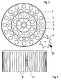
- the rotor 1 is shown from above in FIG. 2. He is in one Bracket 14 arranged, the front a flat stop surface 5, sideways sloping surfaces 6 for centering and rear a handle 7 has.
- the receiving openings 2 for the tubes are arranged and numbered in three concentric rows. For the Both outer rows can be identified automatically through lateral observation slots 8, the z. B. in Fig. 4 are shown. With the help of these observation slits 8 the rotor 1 is also rotated with the aid of a gearwheel 9, which is shown in Fig. 3, that with a motor, in particular is connected to a stepper motor and when inserting or pulling out of the rotor idles so that it has an observation slot 8 can engage.
- the marking is identified, in particular the bar codes of those not shown in the figures Tubes through the observation slits 8 exactly at the point at which the sampling takes place. If a new rotor 1 is inserted, it is first rotated until one Mark 11, which forms the zero position, from the identification device is detected. Then everyone will Tubes in the two outer circular rows "inventoried", so a clear relationship between an individual Tube and its place in the rotor that for renewed examinations or any series of examinations a desired tube can be quickly reached at any time can. The innermost row can be used for emergencies or others unscheduled tests tubes are used, which are then no longer automatically identified can.
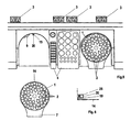
- FIG. 5 shows a second embodiment, in which the reagent unit 4 in the middle between the two rotors 1 is located.
- One of these rotors 1 is outside the device shown.
- the gear 9 and a projection 20th with a ball 19 loaded by a spring 25 (see Fig. 6).
- the holder 14 has at the front (at the location of the reference number 14 in the left rotor 1 in Fig. 5) has a recess that with the projection 20 fits that the bracket 14 only at the correct angle can be used and held at an angle becomes.
- the spring-loaded ball 19 then snaps into the recess a, so that the bracket 14 and thus the rotor on simple Wisely, yet securely fixed in the device and light can be pulled out again.
- a screw rod 22 is provided, which can be rotated using a handle 21.
- This Screw rod 22 interacts with a screw section 23, which is fixed on the rotatably arranged floor 13. By turning the handle 21, the height of the floor can then 13 can be adjusted.
- the handle 21 can be together with another element 24 together as a holder for insertion serve the rotor in a centrifuge.
Landscapes
- Physics & Mathematics (AREA)
- Health & Medical Sciences (AREA)
- Life Sciences & Earth Sciences (AREA)
- Chemical & Material Sciences (AREA)
- Analytical Chemistry (AREA)
- Biochemistry (AREA)
- General Health & Medical Sciences (AREA)
- General Physics & Mathematics (AREA)
- Immunology (AREA)
- Pathology (AREA)
- Centrifugal Separators (AREA)
- Investigating Or Analysing Materials By Optical Means (AREA)
Description
- Fig. 1
- in Draufsicht eine Ausführungsform des erfindungsgemäßen Geräts;
- Fig. 2
- in Draufsicht einen Rotor mit Halterung;
- Fig. 3
- in schematischer Darstellung von unten den Antrieb des Rotors;
- Fig. 4
- in seitlicher Draufsicht den Rotor;
- Fig. 5
- eine andere Ausführungsform des erfindungsgemäßen Geräts in ähnlicher Darstellung wie in Fig. 1;
- Fig. 6
- ein Detail der Ausführungsform der Fig. 5;
- Fig. 7
- im Schnitt eine Ausführungsform für die Höhenverstellung des Bodens des Rotors;
- Fig. 8
- im Schnitt eine andere Ausführungsform für die Höhenverstellung des Rotors;
- Fig. 9
- die Halterung ohne eingesetzten Rotor;
- Fig. 10
- die Halterung mit eingesetzten Rotor.
Claims (12)
- Gerät zum Analysieren von Körperflüssigkeiten, die in mit einer von außen lesbaren Identifikationsmarkierung versehenen Röhrchen angeordnet sind, mit positiver Probenidentifikation an der Position, an der eine Flüssigkeitsmenge zur Analyse entnommen wird, wobei die Röhrchen in einen drehbaren Rotor (1) einsetzbar sind, dadurch gekennzeichnet, daß es mindestens zwei Rotoren (1), die schubladenartig in das Gerät einschiebbar sind, und für jeden Rotor (1) ein seitlich angeordnetes Zahnrad (9) aufweist, über das der entsprechende Rotor antreibbar ist und das in die am Umfang des Rotors (1) angeordneten Beobachtungsschlitze (8) eingreift, durch die die Identifikation der Röhrchen erfolgt.
- Gerät nach Anspruch 1, dadurch gekennzeichnet, daß die Rotoren (1) am Umfang mit einer durch die Identifikationseinrichtung lesbaren Markierung (11) für eine Bezugsstellung (Nullstellung) versehen sind.
- Gerät nach Anspruch 1 oder 2, dadurch gekennzeichnet, daß die Zahnräder (9) mit einem Positionssensor (10) versehen sind.
- Gerät nach einem der Ansprüche 1 bis 3, dadurch gekennzeichnet, daß das Zahnrad (9) beim Einschieben/Herausziehen eines Rotors (1) leer mitläuft.
- Gerät nach einem der Ansprüche 1 bis 4, dadurch gekennzeichnet, daß im Rotor (1) zusätzlich zu zwei konzentrisch kreisförmig angeordneten Reihen von Aufnahmeöffnungen (2) für Röhrchen, die durch die Identifikationseinrichtung identifizierbar sind, eine dritte innen kreisförmig und konzentrisch angeordnete Reihe für außerplanmäßige Untersuchungen vorgesehen ist.
- Gerät nach einem der Ansprüche 1 bis 5, dadurch gekennzeichnet, daß es einen Rechner aufweist.
- Gerät nach einem der Ansprüche 1 bis 6, dadurch gekennzeichnet, daß es an einen externen Rechner anschließbar ist.
- Gerät nach einem der Ansprüche 1 bis 7, dadurch gekennzeichnet, daß die Rotoren (1) einen höhenverstellbaren Boden (13) aufweisen.
- Gerät nach Anspruch 8, dadurch gekennzeichnet, daß der höhenverstellbare Boden (13) durch eine Schraube (15) arretierbar ist, die durch einen der Beobachtungsschlitze (8) zugänglich ist.
- Gerät nach einem der Ansprüche 1 bis 9, dadurch gekennzeichnet, daß die Rotoren (1) in Halterungen (14) eingesetzt sind, die eine flache Vorderseite (5), seitliche, nach vorne zusammenlaufende Zentrierungsflächen (6) und eine Handhabe (7) aufweisen.
- Gerät nach einem der Ansprüche 1 bis 9, dadurch gekennzeichnet, daß die Rotoren (1) in Halterungen (14) eingesetzt sind, die eine halbrunde Vorderseite und eine Ausnehmung aufweisen, die mit einem eine federbelastete Kugel (19) aufweisenden Vorsprung (20) des Geräts zur Winkelfestlegung zusammenwirkt und in die die Kugel (19) einrastet.
- Gerät nach einem der Ansprüche 1 bis 8 und 10 oder 11, dadurch gekennzeichnet, daß durch den Boden (13) eine von oben mit einer Handhabe (21) zur Höhenverstellung drehbare Schraubenstange (22) hindurchgeht, die mit einem Gewindeabschnitt (23) im Boden zusammenwirkt.
Applications Claiming Priority (2)
| Application Number | Priority Date | Filing Date | Title |
|---|---|---|---|
| DE29702276U DE29702276U1 (de) | 1997-02-10 | 1997-02-10 | Analysegerät für Körperflüssigkeit |
| DE29702276U | 1997-02-10 |
Publications (2)
| Publication Number | Publication Date |
|---|---|
| EP0857975A1 EP0857975A1 (de) | 1998-08-12 |
| EP0857975B1 true EP0857975B1 (de) | 2004-05-12 |
Family
ID=8035732
Family Applications (1)
| Application Number | Title | Priority Date | Filing Date |
|---|---|---|---|
| EP98100486A Expired - Lifetime EP0857975B1 (de) | 1997-02-10 | 1998-01-13 | Analysegerät für Körperflüssigkeit |
Country Status (4)
| Country | Link |
|---|---|
| US (1) | US5993741A (de) |
| EP (1) | EP0857975B1 (de) |
| DE (2) | DE29702276U1 (de) |
| ES (1) | ES2219790T3 (de) |
Families Citing this family (3)
| Publication number | Priority date | Publication date | Assignee | Title |
|---|---|---|---|---|
| AT502549B1 (de) * | 2005-10-07 | 2007-06-15 | Anagnostics Bioanalysis Gmbh | Vorrichtung zur analyse von flüssigen proben |
| CN103648647B (zh) * | 2011-07-07 | 2015-04-01 | 霍尔格·彼尼克 | 具有导电的实验皿承载架的实验皿模块 |
| EP2884285B1 (de) * | 2013-12-13 | 2024-07-24 | F. Hoffmann-La Roche AG | Versorgungsmodul für einen automatischen Analysator |
Family Cites Families (9)
| Publication number | Priority date | Publication date | Assignee | Title |
|---|---|---|---|---|
| US3322958A (en) * | 1964-05-07 | 1967-05-30 | American Instr Co Inc | Photometer automatic sample changer |
| JPH0690212B2 (ja) * | 1986-02-21 | 1994-11-14 | 株式会社東芝 | 自動化学分析装置 |
| JPS62278460A (ja) * | 1986-05-28 | 1987-12-03 | Olympus Optical Co Ltd | 自動分析装置 |
| JPH06103312B2 (ja) * | 1987-06-22 | 1994-12-14 | 株式会社日立製作所 | 化学分析装置 |
| CA2384523C (en) * | 1991-03-04 | 2007-01-09 | Bayer Corporation | Automated analyzer |
| JP2745091B2 (ja) * | 1992-04-03 | 1998-04-28 | 東亞医用電子株式会社 | 免疫凝集測定装置 |
| US5424837A (en) * | 1992-09-21 | 1995-06-13 | Porte; Johannes J. | Tube diameter measuring apparatus and method |
| US5518693A (en) * | 1994-06-27 | 1996-05-21 | Johnson & Johnson Clinical Diagnostics, Inc. | Transfer mechanism for automatic loading and unloading of reagent modules |
| JPH09196925A (ja) * | 1996-01-19 | 1997-07-31 | Hitachi Ltd | 自動分析装置 |
-
1997
- 1997-02-10 DE DE29702276U patent/DE29702276U1/de not_active Expired - Lifetime
-
1998
- 1998-01-13 DE DE59811350T patent/DE59811350D1/de not_active Expired - Lifetime
- 1998-01-13 EP EP98100486A patent/EP0857975B1/de not_active Expired - Lifetime
- 1998-01-13 ES ES98100486T patent/ES2219790T3/es not_active Expired - Lifetime
- 1998-01-29 US US09/015,644 patent/US5993741A/en not_active Expired - Lifetime
Also Published As
| Publication number | Publication date |
|---|---|
| DE59811350D1 (de) | 2004-06-17 |
| US5993741A (en) | 1999-11-30 |
| DE29702276U1 (de) | 1998-06-04 |
| ES2219790T3 (es) | 2004-12-01 |
| EP0857975A1 (de) | 1998-08-12 |
Similar Documents
| Publication | Publication Date | Title |
|---|---|---|
| DE3717907C2 (de) | ||
| DE2755264C3 (de) | Anlage zur chemischen Analyse | |
| EP2207019B1 (de) | Wägegutträger für eine Waage | |
| DE3905465C2 (de) | Vorrichtung zum Färben von Geweben für die Beobachtung von Immunantworten | |
| DE7925075U1 (de) | Pipettier- und dosiervorrichtung | |
| DE69322966T2 (de) | Vorrichtung zum aufbringen einer flüssigen probe auf ein kulturmedium | |
| DE3520962C2 (de) | ||
| DE69006905T2 (de) | Analysator mit kreisförmiger, auf einen Inkubator zentrierter Kassettenbahn und Verfahren zu seiner Verwendung. | |
| EP0431455A2 (de) | Teststreifenauswertegerät für Mehrfachteststreifen | |
| DE4110380A1 (de) | Automatische analysiervorrichtung | |
| DE1941366A1 (de) | Blutprobenanalysator | |
| DE69807026T2 (de) | Verfahren und Gerät zur schrittweisen Verteilung einer Blutprobe | |
| DE1673343B2 (de) | Automatische Aliquot-Teileinrichtung | |
| DE69111394T2 (de) | Einwegvorrichtung zur Prüfung einer Flüssigkeit. | |
| DE3625704A1 (de) | Vorrichtung zum feststellen der lage der testfelder eines teststreifens und wenden desselben | |
| DE1673096A1 (de) | Verfahren zur Einfuehrung von Fluessigkeitsproben in eine Messzelle einer Messvorrichtung,sowie Vorrichtung zur Ausuebung des Verfahrens | |
| EP0857975A1 (de) | Analysegerät für Körperflüssigkeit | |
| DE2005385A1 (de) | Verfahren und Vorrichtung zur Radio aktivitatsbestimmung von großmengigen Pro ben | |
| EP0046461B1 (de) | Dosiervorrichtungen für Flüssigkeiten oder Gase | |
| DE2514193A1 (de) | Geraet zum automatischen analysieren fluessiger proben | |
| DE69323851T2 (de) | Vorrichtung zur Handhabung einer Spritze, und biologischer Analyseautomat, eine solche Vorrichtung enthaltend | |
| DE69405779T2 (de) | Verfahren und vorrichtung zum sammeln flüssiger proben | |
| DE2341158A1 (de) | Automatische analysiervorrichtung, insbesondere fuer klinische und pharmazeutische zwecke | |
| DE3104617A1 (de) | Analysengeraet zur messung von fluessigkeitsproben und einrichtung zur einstellung eines bestimmten betriebszustandes desselben | |
| DE4135420C2 (de) | Verfahren zum Füllen eines Rundmagazins in einem Milchproben-Identifikationssystem und Probeflaschen-Rundmagazin |
Legal Events
| Date | Code | Title | Description |
|---|---|---|---|
| PUAI | Public reference made under article 153(3) epc to a published international application that has entered the european phase |
Free format text: ORIGINAL CODE: 0009012 |
|
| AK | Designated contracting states |
Kind code of ref document: A1 Designated state(s): DE ES FR IT |
|
| AX | Request for extension of the european patent |
Free format text: AL;LT;LV;MK;RO;SI |
|
| 17P | Request for examination filed |
Effective date: 19981016 |
|
| AKX | Designation fees paid |
Free format text: DE ES FR IT |
|
| RBV | Designated contracting states (corrected) |
Designated state(s): DE ES FR IT |
|
| 17Q | First examination report despatched |
Effective date: 20021018 |
|
| GRAP | Despatch of communication of intention to grant a patent |
Free format text: ORIGINAL CODE: EPIDOSNIGR1 |
|
| GRAS | Grant fee paid |
Free format text: ORIGINAL CODE: EPIDOSNIGR3 |
|
| GRAA | (expected) grant |
Free format text: ORIGINAL CODE: 0009210 |
|
| AK | Designated contracting states |
Kind code of ref document: B1 Designated state(s): DE ES FR IT |
|
| REF | Corresponds to: |
Ref document number: 59811350 Country of ref document: DE Date of ref document: 20040617 Kind code of ref document: P |
|
| REG | Reference to a national code |
Ref country code: ES Ref legal event code: FG2A Ref document number: 2219790 Country of ref document: ES Kind code of ref document: T3 |
|
| ET | Fr: translation filed | ||
| PLBE | No opposition filed within time limit |
Free format text: ORIGINAL CODE: 0009261 |
|
| STAA | Information on the status of an ep patent application or granted ep patent |
Free format text: STATUS: NO OPPOSITION FILED WITHIN TIME LIMIT |
|
| 26N | No opposition filed |
Effective date: 20050215 |
|
| REG | Reference to a national code |
Ref country code: FR Ref legal event code: PLFP Year of fee payment: 19 |
|
| REG | Reference to a national code |
Ref country code: FR Ref legal event code: PLFP Year of fee payment: 20 |
|
| PGFP | Annual fee paid to national office [announced via postgrant information from national office to epo] |
Ref country code: FR Payment date: 20170124 Year of fee payment: 20 Ref country code: DE Payment date: 20170324 Year of fee payment: 20 |
|
| PGFP | Annual fee paid to national office [announced via postgrant information from national office to epo] |
Ref country code: IT Payment date: 20170125 Year of fee payment: 20 Ref country code: ES Payment date: 20170124 Year of fee payment: 20 |
|
| REG | Reference to a national code |
Ref country code: DE Ref legal event code: R071 Ref document number: 59811350 Country of ref document: DE |
|
| REG | Reference to a national code |
Ref country code: ES Ref legal event code: FD2A Effective date: 20180508 |
|
| PG25 | Lapsed in a contracting state [announced via postgrant information from national office to epo] |
Ref country code: ES Free format text: LAPSE BECAUSE OF EXPIRATION OF PROTECTION Effective date: 20180114 |