EP0855830A2 - Unterscheidung zwischen Text/Linien und Halbtonrasterung zur Verbesserung der Bildelementauflösung - Google Patents
Unterscheidung zwischen Text/Linien und Halbtonrasterung zur Verbesserung der Bildelementauflösung Download PDFInfo
- Publication number
- EP0855830A2 EP0855830A2 EP97115764A EP97115764A EP0855830A2 EP 0855830 A2 EP0855830 A2 EP 0855830A2 EP 97115764 A EP97115764 A EP 97115764A EP 97115764 A EP97115764 A EP 97115764A EP 0855830 A2 EP0855830 A2 EP 0855830A2
- Authority
- EP
- European Patent Office
- Prior art keywords
- pixel
- orphan
- image
- bitmap
- text
- Prior art date
- Legal status (The legal status is an assumption and is not a legal conclusion. Google has not performed a legal analysis and makes no representation as to the accuracy of the status listed.)
- Granted
Links
- 238000000034 method Methods 0.000 claims abstract description 56
- 238000009877 rendering Methods 0.000 claims abstract description 41
- 238000012545 processing Methods 0.000 claims abstract description 14
- 239000011159 matrix material Substances 0.000 claims description 34
- 238000005070 sampling Methods 0.000 abstract description 15
- 238000001514 detection method Methods 0.000 description 24
- 230000008569 process Effects 0.000 description 13
- 239000000872 buffer Substances 0.000 description 9
- 238000010586 diagram Methods 0.000 description 9
- 238000009499 grossing Methods 0.000 description 6
- 238000013507 mapping Methods 0.000 description 5
- 230000002708 enhancing effect Effects 0.000 description 4
- 239000002245 particle Substances 0.000 description 4
- 108091008695 photoreceptors Proteins 0.000 description 4
- 240000002834 Paulownia tomentosa Species 0.000 description 3
- 235000010678 Paulownia tomentosa Nutrition 0.000 description 3
- 238000005516 engineering process Methods 0.000 description 3
- 238000003491 array Methods 0.000 description 2
- 230000003139 buffering effect Effects 0.000 description 2
- 238000006243 chemical reaction Methods 0.000 description 2
- 230000004075 alteration Effects 0.000 description 1
- 230000015556 catabolic process Effects 0.000 description 1
- 230000008859 change Effects 0.000 description 1
- 238000004140 cleaning Methods 0.000 description 1
- 230000000295 complement effect Effects 0.000 description 1
- 238000006731 degradation reaction Methods 0.000 description 1
- 230000000593 degrading effect Effects 0.000 description 1
- 238000013461 design Methods 0.000 description 1
- 230000003292 diminished effect Effects 0.000 description 1
- 230000000694 effects Effects 0.000 description 1
- 238000013073 enabling process Methods 0.000 description 1
- 238000011156 evaluation Methods 0.000 description 1
- 230000006870 function Effects 0.000 description 1
- 238000003384 imaging method Methods 0.000 description 1
- 230000000977 initiatory effect Effects 0.000 description 1
- 239000000463 material Substances 0.000 description 1
- 230000004048 modification Effects 0.000 description 1
- 238000012986 modification Methods 0.000 description 1
- 238000005457 optimization Methods 0.000 description 1
- 238000000059 patterning Methods 0.000 description 1
- 230000035945 sensitivity Effects 0.000 description 1
Images


Classifications
-
- H—ELECTRICITY
- H04—ELECTRIC COMMUNICATION TECHNIQUE
- H04N—PICTORIAL COMMUNICATION, e.g. TELEVISION
- H04N1/00—Scanning, transmission or reproduction of documents or the like, e.g. facsimile transmission; Details thereof
- H04N1/40—Picture signal circuits
- H04N1/40062—Discrimination between different image types, e.g. two-tone, continuous tone
Definitions
- This invention relates in general to imaging systems and pixel resolution enhancement and, more particularly, to rendering of complex images having text, line art, and/or halftones.
- Electrophotographic processes for producing a permanent image on media are well known and commonly used.
- a common process includes: (1) charging a photoreceptor such as a roller or continuous belt bearing a photoconductive material; (2) exposing the charged area to a light image to produce an electrostatic charge on the area in the shape of the image; (3) presenting developer particles (toner) to the photoreceptor surface bearing the image so that the particles are transferred to the surface in the shape of the image; (4) transferring the particles in the shape of the image from the photoreceptor to the media; (5) fusing or fixing the particles in the shape of the image to the media; and (6) cleaning or restoring the photoreceptor for the next printing cycle.
- Many image forming apparatus such as laser printers, copy machines, and facsimile machines, utilize this well known electrophotographic printing process.
- an image is typically rasterized to form a bit pattern which is stored as a binary image bitmap for subsequent rendering to a final output image.
- the image bitmap is also referred to as a picture element ( " pixel " ) raster image.
- graphic elements such as continuous lines (line art) and text character outlines are converted to pixel patterns that approximate the source image shape.
- Continuous tone data such as photographic data (both color and gray value images) are also converted to pixel patterns that approximate the source continuous tone image data.
- each pixel of the source image must be represented by multiple bits which define either a color or a gray level and which are subsequently converted, typically, to a binary image bitmap.
- gray when used, it applies to both color and black/white images and, when applied to a color image, relates to the intensity of the color.
- the pixel data in order to represent gray level images on a bi-level (black and white) printer, is converted into a gray level, multi-bit configuration.
- a gray level, multi-bit configuration For example, when a multi-bit configuration of 8 bits per pixel is employed, 256 gray levels can be represented by the digital pixel values.
- the individual gray level pixels are converted to binary level pixels (i.e., bi-level data for subsequent rendering) through the use of a dithering process.
- Spatial dithering or digital halftoning is the converting of the multi-bit pixel values (of a source image) to fixed-size, binary, multi-pixel groupings that approximate the average gray value of the corresponding source data.
- This dithering process provides a halftone texture to selected areas of the image so as to provide gray value variations therein.
- a 6 x 6 multi-pixel grouping can, in theory, simulate 36 levels of gray, and an 8 x 8 grouping can simulate 64 levels.
- the dithering process employs a comparison of the individual pixel values (specified by a source image intensity array) against a threshold matrix (dither matrix or device best threshold array) to control the conversion of the gray level values to appropriate patterns of bi-level data.
- a gray level value of 255 in a source image is considered to be " white "
- a gray level value of 0 is " black " .
- the threshold matrix comprises a plurality of row-arranged gray level values which control the conversion of the gray level pixel values to bi-level pixel values which are stored in a resultant page buffer array (raster) bitmap.
- each entry in the threshold matrix is a threshold gray level value which, if exceeded by the source image gray level pixel value, causes that gray level image pixel to be converted to a " white " pixel (or a binary logical " zero " ). If, by contrast, the source image gray level pixel value is less than or equal to the corresponding threshold matrix gray level value, it is converted to a "black” pixel (or a binary logical " one " , i.e., a complementary or opposite pixel value relative to " zero " ).
- a raster page buffer array bitmap is generated from a source image, whether the image is text, line art, or halftone
- the desired output image is created (rendered) by causing a laser to be modulated in accordance with the bit pattern stored in the image page buffer array bitmap.
- the modulated laser beam is scanned across a charged surface of a photosensitive drum in a succession of raster scan lines. Each scan line is divided into the pixel areas and the modulated laser beam causes some pixel areas to be exposed to a light pulse and some not, thus causing a pattern of overlapping pixels on each scan line.
- the photosensitive drum is discharged, so that when it is subsequently toned, the toner adheres to the discharged areas and is repelled by the still charged areas.
- the toner that is adhered to the discharged areas is then transferred to paper and fixed in a known manner.
- the fidelity of the output image relative to the source data is directly related to the resolution of pixels (dots) in the output image.
- Arbitrary analog images cannot be exactly reproduced by a bitmap raster. For example, as a result of the images's pixel configuration, image edges that are either not parallel to the raster scan direction or not perpendicular to it appear stepped. This is especially noted in text and line art.
- enhancement techniques include: edge smoothing, fine line broadening, antialiasing (to smooth jagged edges), and increasing the resolution of the laser printer.
- These enhancing techniques typically modify the signals to the laser to produce smaller dots that are usually offset from the pixel center, or in other words, to produce gray scale dots.
- most of the enhancing techniques operate on the data after it has already been rasterized, and hence after the fine detail has already been lost.
- most enhancing techniques employ interpolation methods upon the raster data to " best " render the image.
- Tung discloses a character generator that produces a bitmap of image data and inputs that bitmap into a first-in first-out (FIFO) data buffer.
- FIFO first-in first-out
- a fixed subset of the buffer stored bits forms a sampling window through which a selected block of the bitmap image data may be viewed (for example, a 9 x 9 block of pixels with the edge pixels truncated).
- the sampling window contains a center bit cell which changes on each shift of the image bits through the FIFO buffer.
- the sampling window views successive bit patterns formed by pixels located at the window's center bit cell and its surrounding neighbor bit cells.
- Each bit pattern formed by the center bit and its neighboring bits is compared in a matching network with prestored templates. If a match occurs, indicating that the center bit resides at an image edge and that the pixel it represents can be altered so as to improve the image's resolution, a modulation signal is generated that causes the laser beam to alter the center pixel configuration.
- the center pixel is made smaller than a standard unmodified bitmap pixel and is possibly moved within the confines of the pixel cell.
- RET Resolution Enhancement Technology
- RET edge smoothing
- Text or line art simply has not been distinguishable, and has not been distinguished, from halftone images in raster arrays for any kind of selective application of such resolution enhancement techniques.
- an object of the present invention is to improve the rendering of complex images embodying text, line art and/or halftone data.
- text and line art image data is distinguished from halftone image data for selectively enhanced rendering thereof.
- a method of rendering a raster pixel image from a stored bitmap includes (i) determining whether an orphan pixel is detected within one or more bounded sampling windows of the bitmap, and, (ii) processing at least one selected pixel of the bitmap within the one or more sampling windows relative to the determining of whether an orphan pixel is detected.
- an orphan pixel is defined as an isolated white or black pixel in a halftone image.
- an orphan pixel is recognized as having a predefined pixel value and as having no other pixels with that value adjacent thereto within a sampling window.
- a method of forming a dither matrix for a halftone image includes generating a pixel pattern such that an orphan pixel exists within the pattern of the dither matrix.
- the orphan pixel is designed into the halftone image. This measure increases the probability that orphan pixels will be detected in the resultant raster image array.
- selective application of resolution enhancement techniques may occur based on whether or not an orphan pixel is detected in the sampling window or windows.
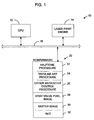
- FIG. 1 is a block diagram of a laser print engine incorporating the invention hereof.
- Figure 2 is a block diagram of a threshold dither matrix embodying orphan pixels according to the present invention.
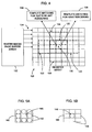
- Figure 3 is a block diagram of a raster image array as generated by a source image having been processed through the dither matrix of Figure 2.
- Figure 4 is a block diagram of a register array having multiple mapping windows for detecting an orphan pixel.
- Figures 5A-B are block diagram pixel arrays of exemplary orphan dot configurations relative to a mapping window.
- Figure 6 is a flow chart depicting a preferred method of the present invention.
- Figure 1 is a block diagram of a laser printer that incorporates the invention hereof for enhanced rendering of a source image by discriminating between text/line art and halftone images based on orphan pixel data. It is to be understood that while a laser printer will be hereafter described, the invention is equally applicable to any device which utilizes multiple gray level pixels (as applicable to black/white or color) to render a halftone image. More specifically, such devices include laser printers, copiers, facsimile devices, plotters, inkjet based devices, etc.
- Laser printer 10 comprises a central processing unit (CPU) 12 and a laser print engine 14, interconnected via a bus 16.
- a read only memory (ROM) and/or random access memory (RAM) and/or application-specific integrated circuit (ASIC) 20 is/are interconnected to bus 16.
- ROM/RAM/ASIC 20 is shown as a single block unit although as is well known in the art they are generally separate units for providing specific functionalities. It is also to be understood that the rendering/rasterizing procedures and data discussed herein for printer 10 may be maintained and utilized as control firmware in any conventional ROM, and/or implemented in an ASIC for high-speed hardware functionality, and/or implemented in connection with RAM for storage and buffering purposes.
- ROM/RAM/ASIC 20 includes procedures and data necessary to enable CPU 12 to carry out the rasterizing, halftoning and rendering functions of the invention. More specifically, ROM/RAM/ASIC 20 includes a halftone procedure 22, text and line art procedure 24, dither matrix and tile control subprocedure 26, and a gray value pixel image 28 (as received from a host processor, not shown) which is to be altered by the invention into a raster image 30, suitable for rendering by laser print engine 14. Halftone raster image 30 may be buffered in RAM or fed directly from an ASIC to print engine 14. Resolution enhancement technology (RET) procedure 32 provides edge smoothing for text and line art stored within raster image 30 upon final rendering.
- RET resolution enhancement technology
- Gray value pixel image 28 is of the known type wherein each pixel is represented by a multi-bit gray value. If gray value pixel image 28 is a color image, it will comprise (generally) four color planes with three of the color planes representing cyan, magenta and yellow color values (or red, green and blue color planes). Moreover, each color value in each plane may be represented by a predetermined number of bits -- for example, by 8 bits. A fourth plane, representing black, may be comprised of single or multiple bit values at each pixel location where a black or gray scale image value is to appear on the ultimate rendered output. Thus there may be a total of 25 to 32 bits per pixel in gray value pixel image 28 if color is embodied.
- FIG. 2 is a block diagram of a threshold dither matrix (device best threshold array) 40 according to the present invention.
- Dither matrix 40 comprises a PxQ matrix (in this example, 16x16) of threshold values.
- a source image gray level pixel value of 255 is considered to be " white "
- a source image gray level value of 0 is " black " .
- each threshold value in each cell of dither matrix 40 represents a level which must be exceeded by a positionally corresponding source image pixel value from gray value pixel image 28 for that image pixel value to be represented by a " white " halftone pixel in raster image 30.
- the criteria for establishing dither matrix 40 includes: (i) establishing an adequate number of gray levels for image quality; (ii) utilizing a mapped gamma (indicative of how fast the gray steps change); (iii) minimizing visible patterning in the gray ramp; (iv) ensuring the pattern is robust to RET degradation (i.e., ensuring that the halftone data will withstand unwanted application of RET, although this aspect is less critical under principles of the present invention because of the use of " orphan " dots); and (v) including an appropriate number of " orphan " pixels (dots) to ensure detection of the same in the subsequent rasterized array and to enable switching between RET template matching and halftone template matching during rendering.
- orphan pixel placement is based on a tradeoff evaluation of all threshold dither criteria discussed, including optimization and line screen issues, and the number of sampling/detection windows used for switching during rendering. The sampling/detection windows will be discussed more fully later.
- Dither matrix 40 provides an exemplary 16x16 super cell that produces a 106 line per inch (lpi) - 600 dot per inch (dpi) binary image.
- the zero (0) values indicate the resultant raster pixel will stay “ white " , no matter the source image pixel value upon rasterizing of gray value pixel image 28.
- the zero (0) values are strategically placed within the matrix per the previously discussed criteria to serve as orphan pixels/dots (or to enhance the existence/detection of orphan pixels) for a 3x3 mapping (rasterizing) window.
- an " orphan " pixel in this example, is any dither matrix pixel having a predefined value of zero (0), other predefined values would likewise suffice given the proper mapping and recognition of the same.
- the orphan pixels are placed in dither matrix 40 to enhance the possibility of having orphan pixels in the resultant raster image 30 for ultimate purposes of discriminating text/line art data from halftone data during rendering.
- the placement of orphan pixels in Figure 2 is merely exemplary, and variations may also serve for a 3x3 sampling/detection window.
- the orphan placement may also vary given a different size window, such as for a 5x5 area window, a 1x3 area window, or for a multiple sampling/detection window configuration.
- raster image array 50 depicts the resultant raster image after dithering has occurred using dither matrix 40 relative to an arbitrary sample source image (gray value pixel image 28) that has all gray pixel values of 128.
- Array 50 is a raster pixel image (stored bitmap) from which rendering occurs.
- Windows 52 and 56 are example sampling/mapping/detection windows (hereinafter " detection " windows) and are depicted as being tiled over raster array 50 within which orphan pixels are found. Although windows 52 and 56 are shown as 3x3 cell/pixel windows, other window configurations are also applicable, such as 5x5 or 1x3, wherein, preferably, a center cell exists.
- an orphan pixel value has a unique (in this case opposite) pixel value relative to a pixel value of any adjacent pixel within a bounded detection window.
- a pixel is an " orphan " pixel if it has a logical value of " zero " and the pixel value of each adjacent pixel (within the window) is a logical " non-zero " or " one " .
- a pixel is also an orphan pixel in array 50 if it has a logical value of " non-zero " or " one " and the pixel value of each adjacent pixel (within the window) is a logical " zero " .
- each window 52 and 56 is shown as a highlighted outline around a prescribed set of 9 pixels for a 3x3 window area. Both windows 52 and 56 are shown simultaneously tiled over raster image 50 for ease of discussion purposes. However, as well known in the art, each window 52 and 56 is representative of a different snap shot in time for rendering different portions of raster image 50.
- Each 3x3 set of pixels is processed through its respective window 52 or 56. If an orphan bit is found within the window, the pixel data (or, generally, the selected center pixel) is subsequently processed as halftone data. In contrast, if an orphan bit is not found, the pixel data is processed as text/line art data.
- window 52 is tiled over a first set of 9 pixels.
- pixel 54 is identified as an orphan pixel because all adjacent pixels (within window 52) have an opposite binary value/state.
- orphan pixel 54 has a value (state) of logical " zero "
- all adjacent pixels have a value of logical " one " .
- window 56 is tiled over a second set of pixels wherein pixel 58 is identified as an orphan pixel.
- orphan pixel 58 has a value of " one " and is identified as an orphan because all adjacent pixels (within the window) have a value of " zero " .
- detection windows 52 and 56 depict preferred orphan configurations, i.e., the center cell in the window comprises an orphan bit
- the definition of " orphan " is flexible under the present invention. Namely, a pixel may optionally be considered orphan even if it is located in a non-center cell within the detection window, so long as each adjacent cell pixel within the window contains a different or opposite binary value/state relative to the " orphan " pixel. Or, in other words, a pixel may be considered “ orphan " regardless of its location within a detection window if it is unique relative to any adjacent pixels.
- an orphan cell may be flexibly defined, so long as it is usable/identifiable to distinguish between halftone, text, and/or line art under principles of the present invention.
- an orphan pixel may be defined by any number of bits as conventional in the art for defining pixel values.
- a multi-bit pixel definition is applicable not only to dither matrix 40, but also to raster image array 50. For example, if raster array 50 embodied two-bit pixel values, an orphan pixel may be identified as a " 00" with adjacent pixels being any other combination, such as 01, 10, or 11. Or, an orphan pixel may be identified as a " 11" with adjacent pixels being any other combination, such as 00, 01, or 10.
- Figure 4 is a block diagram of register array 120 and raster image array 132, further describing the rendering of data having orphan pixels according to the present invention.
- Register array 120 is a 9x9 array (for this example) and receives data in a conventional manner from raster image/page buffer array 132 through five line 600 dpi buffers 134.
- Center bit cell 136 is marked with an " X " to show the active/selected cell for which rendering occurs as data is serially shifted through register array 120.
- register array 120 includes multiple overlapping detection windows 122, 124, 126, 128 and 130 for detecting orphan pixels and for enabling process " switching " for the image data ( " switching " will be defined later).
- center window 122 is highlighted in a solid line, whereas windows 124, 126, 128 and 130 are highlighted in short dashed lines.
- Each window 124, 126, 128 and 130 overlaps center window 122 by a single row (or column) of pixels.
- the use of multiple detection windows provides a preferred configuration and method for enhancing the detection of orphan dots relative to the overall data being rendered and for discriminating as to when process " switching " should occur. Specifically, if an orphan pixel is identified within any of the detection windows 122, 124, 126, 128 and 130, or as programmably defined, then the center cell pixel 136 is template matched for gray rendering 138 (halftoning) purposes. In contrast, if no orphan pixel is identified within any of the detection windows, then the center cell is template matched for text/line art rendering 139 purposes. Thus, " switching " means that rendering may occur, selectively, under halftone processing 138 or under text/line art processing 139.
- one option is to immediately switch to halftone rendering 138 and then immediately switch back to text/line art rendering when no orphan pixel is detected.
- another option is to switch to halftone rendering 138, set a counter to a predefined number, and then continue halftone rendering 138 and stepping the counter for each next pixel encountered until the counter has expired. If another orphan pixel is detected before the counter has expired, then the counter is reset. Once the counter expires, then switch back to text/line art rendering.
- a third embodiment includes encoding only the edges of a halftone image with orphan dots so as to allow for detecting an orphan dot and initiating halftone rendering 138 at a first edge of the image, and then subsequently detecting an orphan dot and terminating halftone rendering at a second/opposite edge of the image.
- these three detection/switching schemes are exemplary only, and the details of implementation for a preferred or other detection schemes may vary depending on sensitivity desired and other specific design factors.
- Figures 5A-B are block diagrams of exemplary " robust " or most accurate orphan dot configurations.
- white " pixel 140 is the orphan dot because it is completely surrounded by opposite value ( “ black " ) dots 142.
- black " pixel 146 is an orphan dot because it is surrounded by opposite value ( " white " ) dots 148.
- Other pixel configurations are also feasible for defining an orphan dot as is obvious to those of ordinary skill in the art.
- the image data is deemed to be halftone data 100 and no edge smoothing or resolution enhancement technology (RET) is applied to the active pixel selected for processing (usually a center cell of a detection window).
- RET resolution enhancement technology
- other halftone template matching may be selectively applied to enhance the halftone image.
- the window data is deemed to be text or line art and the active pixel is processed through RET or other resolution enhancement procedures.
- the rendering process continues 110, 115, 95, etc., until completed.
Landscapes
- Engineering & Computer Science (AREA)
- Multimedia (AREA)
- Signal Processing (AREA)
- Facsimile Image Signal Circuits (AREA)
- Image Processing (AREA)
- Record Information Processing For Printing (AREA)
- Color, Gradation (AREA)
Applications Claiming Priority (2)
| Application Number | Priority Date | Filing Date | Title |
|---|---|---|---|
| US788768 | 1997-01-24 | ||
| US08/788,768 US5987221A (en) | 1997-01-24 | 1997-01-24 | Encoded orphan pixels for discriminating halftone data from text and line art data |
Publications (3)
| Publication Number | Publication Date |
|---|---|
| EP0855830A2 true EP0855830A2 (de) | 1998-07-29 |
| EP0855830A3 EP0855830A3 (de) | 2000-02-23 |
| EP0855830B1 EP0855830B1 (de) | 2011-02-23 |
Family
ID=25145498
Family Applications (1)
| Application Number | Title | Priority Date | Filing Date |
|---|---|---|---|
| EP97115764A Expired - Lifetime EP0855830B1 (de) | 1997-01-24 | 1997-09-10 | Unterscheidung zwischen Text/Linien und Halbtonrasterung zur Verbesserung der Bildelementauflösung |
Country Status (4)
| Country | Link |
|---|---|
| US (1) | US5987221A (de) |
| EP (1) | EP0855830B1 (de) |
| JP (2) | JP3822975B2 (de) |
| DE (1) | DE69740128D1 (de) |
Cited By (1)
| Publication number | Priority date | Publication date | Assignee | Title |
|---|---|---|---|---|
| EP0899685A1 (de) * | 1997-08-20 | 1999-03-03 | Kabushiki Kaisha Toshiba | Verfahren und Vorrichtung zur mehrmaligen Unterscheidung von Bildfeldern einer Vorlage |
Families Citing this family (32)
| Publication number | Priority date | Publication date | Assignee | Title |
|---|---|---|---|---|
| DE19635761A1 (de) * | 1996-09-03 | 1998-03-05 | Giesecke & Devrient Gmbh | Dokument mit moirE-erzeugender Rasterstruktur |
| JP3755854B2 (ja) * | 1997-04-07 | 2006-03-15 | 理想科学工業株式会社 | 画像処理装置および二次元線特徴量算出装置 |
| US6160913A (en) * | 1998-03-25 | 2000-12-12 | Eastman Kodak Company | Method and apparatus for digital halftone dots detection and removal in business documents |
| US6173281B1 (en) * | 1998-05-22 | 2001-01-09 | International Business Machines Corporation | Method and computer program product for processing and combining data sets including bitmaps |
| US6137907A (en) * | 1998-09-23 | 2000-10-24 | Xerox Corporation | Method and apparatus for pixel-level override of halftone detection within classification blocks to reduce rectangular artifacts |
| US6128408A (en) * | 1998-09-23 | 2000-10-03 | Xerox Corporation | Method for augmenting sum-of-laplacians in light and dark areas of halftone field to maintain reliable segmentation |
| US6289122B1 (en) * | 1999-04-15 | 2001-09-11 | Electronics For Imaging, Inc. | Intelligent detection of text on a page |
| US6642962B1 (en) * | 1999-09-01 | 2003-11-04 | Neomagic Corp. | Merged pipeline for color interpolation and edge enhancement of digital images |
| US6628330B1 (en) | 1999-09-01 | 2003-09-30 | Neomagic Corp. | Color interpolator and horizontal/vertical edge enhancer using two line buffer and alternating even/odd filters for digital camera |
| JP3392798B2 (ja) * | 2000-02-22 | 2003-03-31 | 理想科学工業株式会社 | 画像属性判別方法および装置 |
| US6775410B1 (en) * | 2000-05-25 | 2004-08-10 | Xerox Corporation | Image processing method for sharpening corners of text and line art |
| US6785416B1 (en) * | 2000-10-17 | 2004-08-31 | Oak Technology, Inc. | System and method for the processing of scanned image data using a pixel window |
| US6778700B2 (en) * | 2001-03-14 | 2004-08-17 | Electronics For Imaging, Inc. | Method and apparatus for text detection |
| US7106462B2 (en) * | 2001-04-02 | 2006-09-12 | Hewlett-Packard Development Company, L.P. | Systems and methods for analyzing a print job |
| US7167185B1 (en) | 2002-03-22 | 2007-01-23 | Kla- Tencor Technologies Corporation | Visualization of photomask databases |
| US7046863B2 (en) * | 2002-03-25 | 2006-05-16 | Sharp Laboratories Of America, Inc. | Optimizing the advantages of multi-level rendering |
| US20040205662A1 (en) * | 2002-05-30 | 2004-10-14 | Brad Anderson | Image preservation and reconstruction |
| US6914700B2 (en) | 2003-04-17 | 2005-07-05 | Lexmark International, Inc. | Method for reducing migrating residual error in error diffusion halftoning |
| US7422310B2 (en) * | 2003-04-25 | 2008-09-09 | Hewlett-Packard Development Company, L.P. | Methods and apparatus for selecting image enhancement techniques |
| US7933446B2 (en) * | 2004-01-28 | 2011-04-26 | Transpacific Optics Llc | Method and apparatus for automatically detecting image and character data |
| KR100611981B1 (ko) | 2004-05-01 | 2006-08-11 | 삼성전자주식회사 | 이미지의 하프토닝 방법 및 장치 |
| JP2006033797A (ja) * | 2004-06-17 | 2006-02-02 | Ricoh Co Ltd | 画像処理装置及び画像処理方法 |
| US8406523B1 (en) | 2005-12-07 | 2013-03-26 | Mcafee, Inc. | System, method and computer program product for detecting unwanted data using a rendered format |
| US8189237B2 (en) | 2006-12-19 | 2012-05-29 | Xerox Corporation | Distributing a SRE codes in halftone pixels pattern in supercell |
| US8599439B2 (en) | 2007-12-21 | 2013-12-03 | Csr Imaging Us, Lp | Laser color copy image processing independent of classifications |
| US8180152B1 (en) | 2008-04-14 | 2012-05-15 | Mcafee, Inc. | System, method, and computer program product for determining whether text within an image includes unwanted data, utilizing a matrix |
| JP4795406B2 (ja) * | 2008-08-27 | 2011-10-19 | シャープ株式会社 | 画像処理装置、画像形成装置、画像処理装置の制御方法、制御プログラム、記録媒体 |
| JP4763026B2 (ja) * | 2008-08-27 | 2011-08-31 | シャープ株式会社 | 画像処理装置、画像形成装置、画像処理方法、画像処理プログラム及びコンピュータ読み取り可能な記録媒体 |
| JP4610644B2 (ja) * | 2008-08-27 | 2011-01-12 | シャープ株式会社 | 画像処理装置、画像形成装置、画像処理方法、画像処理プログラム及びコンピュータ読み取り可能な記録媒体 |
| JP4865771B2 (ja) * | 2008-08-27 | 2012-02-01 | シャープ株式会社 | 画像処理装置、画像形成装置、画像処理方法、画像処理プログラム及びコンピュータ読み取り可能な記録媒体 |
| JP4764938B2 (ja) * | 2009-04-07 | 2011-09-07 | シャープ株式会社 | 画像処理装置、画像形成装置、画像処理装置の制御方法、プログラム、記録媒体 |
| JP6531471B2 (ja) * | 2014-07-29 | 2019-06-19 | 株式会社リコー | 画像形成装置、ディザパターン生成装置およびディザパターン生成方法 |
Citations (9)
| Publication number | Priority date | Publication date | Assignee | Title |
|---|---|---|---|---|
| US4847641A (en) * | 1988-08-16 | 1989-07-11 | Hewlett-Packard Company | Piece-wise print image enhancement for dot matrix printers |
| US4975785A (en) * | 1989-08-04 | 1990-12-04 | International Business Machines Corporation | Pel resolution addressing conversion |
| US5235436A (en) * | 1990-03-02 | 1993-08-10 | Canon Kabushiki Kaisha | Image processing apparatus |
| US5268774A (en) * | 1991-11-27 | 1993-12-07 | Xerox Corporation | Halftoning with enhanced dynamic range and edge enhanced error diffusion |
| EP0680194A2 (de) * | 1994-04-28 | 1995-11-02 | Ricoh Company, Ltd | Bildverarbeitungsvorrichtung und Bildausgabevorrichtung zur Umsetzung eines binären Bildes in ein mehrwertiges Bild |
| JPH0951438A (ja) * | 1995-08-02 | 1997-02-18 | Fuji Xerox Co Ltd | 画像処理装置 |
| EP0805586A2 (de) * | 1996-04-30 | 1997-11-05 | Dainippon Screen Mfg. Co., Ltd. | Verfahren und Vorrichtung zum Erzeugen von Rasterpunkten für den Farbdruck |
| EP0845717A2 (de) * | 1996-11-29 | 1998-06-03 | Kabushiki Kaisha Toshiba | Bildverarbeitungsgerät mit Glättungseigenschaft |
| EP0898414A2 (de) * | 1997-08-21 | 1999-02-24 | Sharp Kabushiki Kaisha | Vorrichtung zum Erkennen von Bildbereichen |
Family Cites Families (6)
| Publication number | Priority date | Publication date | Assignee | Title |
|---|---|---|---|---|
| JPS62137974A (ja) * | 1985-12-12 | 1987-06-20 | Ricoh Co Ltd | 画像処理方式 |
| EP0650287B1 (de) * | 1993-10-26 | 2004-03-10 | Canon Kabushiki Kaisha | Bildverarbeitungsverfahren und -gerät |
| EP0724229B1 (de) * | 1994-12-28 | 2001-10-10 | Canon Kabushiki Kaisha | Bildverarbeitungsvorrichtung und Verfahren |
| JPH096957A (ja) * | 1995-06-23 | 1997-01-10 | Toshiba Corp | 濃度画像の2値化方法および画像2値化装置 |
| US5742703A (en) * | 1995-10-11 | 1998-04-21 | Xerox Corporation | Method and apparatus for the resolution enhancement of gray-scale images that include text and line art |
| US5764812A (en) * | 1995-11-10 | 1998-06-09 | Ricoh Company, Ltd. | Image processing apparatus for providing an isolated-dot removing function |
-
1997
- 1997-01-24 US US08/788,768 patent/US5987221A/en not_active Expired - Lifetime
- 1997-09-10 EP EP97115764A patent/EP0855830B1/de not_active Expired - Lifetime
- 1997-09-10 DE DE69740128T patent/DE69740128D1/de not_active Expired - Lifetime
-
1998
- 1998-01-23 JP JP01172398A patent/JP3822975B2/ja not_active Expired - Fee Related
-
2003
- 2003-01-27 JP JP2003017903A patent/JP2003264695A/ja active Pending
Patent Citations (9)
| Publication number | Priority date | Publication date | Assignee | Title |
|---|---|---|---|---|
| US4847641A (en) * | 1988-08-16 | 1989-07-11 | Hewlett-Packard Company | Piece-wise print image enhancement for dot matrix printers |
| US4975785A (en) * | 1989-08-04 | 1990-12-04 | International Business Machines Corporation | Pel resolution addressing conversion |
| US5235436A (en) * | 1990-03-02 | 1993-08-10 | Canon Kabushiki Kaisha | Image processing apparatus |
| US5268774A (en) * | 1991-11-27 | 1993-12-07 | Xerox Corporation | Halftoning with enhanced dynamic range and edge enhanced error diffusion |
| EP0680194A2 (de) * | 1994-04-28 | 1995-11-02 | Ricoh Company, Ltd | Bildverarbeitungsvorrichtung und Bildausgabevorrichtung zur Umsetzung eines binären Bildes in ein mehrwertiges Bild |
| JPH0951438A (ja) * | 1995-08-02 | 1997-02-18 | Fuji Xerox Co Ltd | 画像処理装置 |
| EP0805586A2 (de) * | 1996-04-30 | 1997-11-05 | Dainippon Screen Mfg. Co., Ltd. | Verfahren und Vorrichtung zum Erzeugen von Rasterpunkten für den Farbdruck |
| EP0845717A2 (de) * | 1996-11-29 | 1998-06-03 | Kabushiki Kaisha Toshiba | Bildverarbeitungsgerät mit Glättungseigenschaft |
| EP0898414A2 (de) * | 1997-08-21 | 1999-02-24 | Sharp Kabushiki Kaisha | Vorrichtung zum Erkennen von Bildbereichen |
Non-Patent Citations (3)
| Title |
|---|
| PATENT ABSTRACTS OF JAPAN vol. 1997, no. 06, 30 June 1997 (1997-06-30) & JP 09 051438 A (FUJI XEROX CO LTD), 18 February 1997 (1997-02-18) * |
| SATOSHI OHUCHI ET AL: "A SEGMENTATION METHOD FOR COMPOSITE TEXT/GRAPHICS (HALFTONE AND CONTINUOUS TONE PHOTOGRAPHS) DOCUMENTS" SYSTEMS & COMPUTERS IN JAPAN,US,SCRIPTA TECHNICA JOURNALS. NEW YORK, vol. 24, no. 2, page 35-44 XP000417662 ISSN: 0882-1666 * |
| TOMIKAWA T: "AN IDENTIFICATION OF PSEUDO CONTINUOUS TONE BY LABELING" INTERNATIONAL DISPLAY RESEARCH CONFERENCE,US,NEW YORK, IEEE, vol. -, page 146-151 XP000123988 * |
Cited By (2)
| Publication number | Priority date | Publication date | Assignee | Title |
|---|---|---|---|---|
| EP0899685A1 (de) * | 1997-08-20 | 1999-03-03 | Kabushiki Kaisha Toshiba | Verfahren und Vorrichtung zur mehrmaligen Unterscheidung von Bildfeldern einer Vorlage |
| US6424742B2 (en) | 1997-08-20 | 2002-07-23 | Kabushiki Kaisha Toshiba | Image processing apparatus for discriminating image field of original document plural times and method therefor |
Also Published As
| Publication number | Publication date |
|---|---|
| JP3822975B2 (ja) | 2006-09-20 |
| EP0855830B1 (de) | 2011-02-23 |
| EP0855830A3 (de) | 2000-02-23 |
| DE69740128D1 (de) | 2011-04-07 |
| JPH10224630A (ja) | 1998-08-21 |
| US5987221A (en) | 1999-11-16 |
| JP2003264695A (ja) | 2003-09-19 |
Similar Documents
| Publication | Publication Date | Title |
|---|---|---|
| US5987221A (en) | Encoded orphan pixels for discriminating halftone data from text and line art data | |
| EP0881822B1 (de) | Auf Leuchtdichte basierte Verbesserung der Farbenauslösung | |
| EP1505821B1 (de) | Bildverarbeitungsvorrichtung, Bilderzeugungsvorrichtung und Bildverarbeitungsverfahren | |
| US5506941A (en) | Pattern generation method and pattern generation apparatus | |
| JP3581477B2 (ja) | デジタル複写機 | |
| EP0768792A2 (de) | Verfahren und Vorrichtung zur Verbesserung des Auflösungsvermögens von Grautonbildern mit Text und Bildern | |
| US6834124B1 (en) | Adaptive image enhancement filter | |
| EP0823811A2 (de) | Bildverarbeitungsverfahren und -system | |
| US6678426B1 (en) | Programmable mapping of lower resolution digital data to a higher resolution for output on a lower resolution device | |
| US20020067509A1 (en) | Method, apparatus and system for dynamic switching of image processing techniques | |
| US6342953B1 (en) | Color plane under exposure for reducing edge effect | |
| JP2644666B2 (ja) | 印刷装置 | |
| KR100869284B1 (ko) | 화상 처리 장치 및 화상 처리 방법 | |
| JPH0725064A (ja) | 電子写真プリンタの画像形成装置 | |
| US6344870B1 (en) | Methods of providing lower resolution format data into higher resolution format | |
| US5485529A (en) | Image processing apparatus with the ability to suppress isolated points | |
| EP0945823B1 (de) | Programmierbare Auflösungumwandlung von digitalen Daten mit niedriger Auflösung zu einer höheren Auflösung für die Wiedergabe auf einem niedrigauflösendem Ausgabegerät | |
| EP0932301B1 (de) | Steuerung der entwickelten Tonermenge unter Verwendung von Lasermodulationen von getrennten Unterelementen eines Bildes | |
| JP4137067B2 (ja) | 画像処理方法及びその装置 | |
| JP3224405B2 (ja) | カラー画像処理装置 | |
| JP3129421B2 (ja) | 画像の階調記録装置 | |
| JP2009134583A (ja) | 画像形成装置及び画像形成方法、コンピュータプログラム及び記録媒体 | |
| JP3183788B2 (ja) | 網点領域判定装置 | |
| EP1370067A1 (de) | Verfahren und System zur Verarbeitung eines mehrfarbigen Bildes | |
| JPH0414380A (ja) | 画像領域識別装置 |
Legal Events
| Date | Code | Title | Description |
|---|---|---|---|
| PUAI | Public reference made under article 153(3) epc to a published international application that has entered the european phase |
Free format text: ORIGINAL CODE: 0009012 |
|
| AK | Designated contracting states |
Kind code of ref document: A2 Designated state(s): DE FR GB |
|
| PUAL | Search report despatched |
Free format text: ORIGINAL CODE: 0009013 |
|
| AK | Designated contracting states |
Kind code of ref document: A3 Designated state(s): AT BE CH DE DK ES FI FR GB GR IE IT LI LU MC NL PT SE |
|
| 17P | Request for examination filed |
Effective date: 20000613 |
|
| AKX | Designation fees paid |
Free format text: DE FR GB |
|
| RAP1 | Party data changed (applicant data changed or rights of an application transferred) |
Owner name: HEWLETT-PACKARD COMPANY, A DELAWARE CORPORATION |
|
| 17Q | First examination report despatched |
Effective date: 20041216 |
|
| GRAP | Despatch of communication of intention to grant a patent |
Free format text: ORIGINAL CODE: EPIDOSNIGR1 |
|
| GRAS | Grant fee paid |
Free format text: ORIGINAL CODE: EPIDOSNIGR3 |
|
| GRAA | (expected) grant |
Free format text: ORIGINAL CODE: 0009210 |
|
| AK | Designated contracting states |
Kind code of ref document: B1 Designated state(s): DE FR GB |
|
| REG | Reference to a national code |
Ref country code: GB Ref legal event code: FG4D |
|
| REF | Corresponds to: |
Ref document number: 69740128 Country of ref document: DE Date of ref document: 20110407 Kind code of ref document: P |
|
| REG | Reference to a national code |
Ref country code: DE Ref legal event code: R096 Ref document number: 69740128 Country of ref document: DE Effective date: 20110407 |
|
| PLBE | No opposition filed within time limit |
Free format text: ORIGINAL CODE: 0009261 |
|
| STAA | Information on the status of an ep patent application or granted ep patent |
Free format text: STATUS: NO OPPOSITION FILED WITHIN TIME LIMIT |
|
| 26N | No opposition filed |
Effective date: 20111124 |
|
| REG | Reference to a national code |
Ref country code: DE Ref legal event code: R097 Ref document number: 69740128 Country of ref document: DE Effective date: 20111124 |
|
| REG | Reference to a national code |
Ref country code: GB Ref legal event code: 732E Free format text: REGISTERED BETWEEN 20120329 AND 20120404 |
|
| REG | Reference to a national code |
Ref country code: DE Ref legal event code: R082 Ref document number: 69740128 Country of ref document: DE Representative=s name: BOEHMERT & BOEHMERT, DE |
|
| REG | Reference to a national code |
Ref country code: DE Ref legal event code: R082 Ref document number: 69740128 Country of ref document: DE Representative=s name: BOEHMERT & BOEHMERT ANWALTSPARTNERSCHAFT MBB -, DE Effective date: 20120611 Ref country code: DE Ref legal event code: R081 Ref document number: 69740128 Country of ref document: DE Owner name: HEWLETT-PACKARD DEVELOPMENT COMPANY, L.P., HOU, US Free format text: FORMER OWNER: HEWLETT-PACKARD CO., PALO ALTO, CALIF., US Effective date: 20120611 |
|
| REG | Reference to a national code |
Ref country code: FR Ref legal event code: PLFP Year of fee payment: 19 |
|
| PGFP | Annual fee paid to national office [announced via postgrant information from national office to epo] |
Ref country code: DE Payment date: 20150820 Year of fee payment: 19 Ref country code: GB Payment date: 20150825 Year of fee payment: 19 |
|
| PGFP | Annual fee paid to national office [announced via postgrant information from national office to epo] |
Ref country code: FR Payment date: 20150824 Year of fee payment: 19 |
|
| REG | Reference to a national code |
Ref country code: DE Ref legal event code: R119 Ref document number: 69740128 Country of ref document: DE |
|
| GBPC | Gb: european patent ceased through non-payment of renewal fee |
Effective date: 20160910 |
|
| REG | Reference to a national code |
Ref country code: FR Ref legal event code: ST Effective date: 20170531 |
|
| PG25 | Lapsed in a contracting state [announced via postgrant information from national office to epo] |
Ref country code: GB Free format text: LAPSE BECAUSE OF NON-PAYMENT OF DUE FEES Effective date: 20160910 Ref country code: FR Free format text: LAPSE BECAUSE OF NON-PAYMENT OF DUE FEES Effective date: 20160930 Ref country code: DE Free format text: LAPSE BECAUSE OF NON-PAYMENT OF DUE FEES Effective date: 20170401 |