EP0855498A2 - Elektronisches Berechnungssystem der Gemischzusammensetzung - Google Patents
Elektronisches Berechnungssystem der Gemischzusammensetzung Download PDFInfo
- Publication number
- EP0855498A2 EP0855498A2 EP98105228A EP98105228A EP0855498A2 EP 0855498 A2 EP0855498 A2 EP 0855498A2 EP 98105228 A EP98105228 A EP 98105228A EP 98105228 A EP98105228 A EP 98105228A EP 0855498 A2 EP0855498 A2 EP 0855498A2
- Authority
- EP
- European Patent Office
- Prior art keywords
- block
- petrol
- state
- threshold
- engine
- Prior art date
- Legal status (The legal status is an assumption and is not a legal conclusion. Google has not performed a legal analysis and makes no representation as to the accuracy of the status listed.)
- Granted
Links
Images


Classifications
-
- F—MECHANICAL ENGINEERING; LIGHTING; HEATING; WEAPONS; BLASTING
- F02—COMBUSTION ENGINES; HOT-GAS OR COMBUSTION-PRODUCT ENGINE PLANTS
- F02D—CONTROLLING COMBUSTION ENGINES
- F02D41/00—Electrical control of supply of combustible mixture or its constituents
- F02D41/02—Circuit arrangements for generating control signals
- F02D41/14—Introducing closed-loop corrections
- F02D41/1438—Introducing closed-loop corrections using means for determining characteristics of the combustion gases; Sensors therefor
- F02D41/1493—Details
- F02D41/1495—Detection of abnormalities in the air/fuel ratio feedback system
-
- F—MECHANICAL ENGINEERING; LIGHTING; HEATING; WEAPONS; BLASTING
- F02—COMBUSTION ENGINES; HOT-GAS OR COMBUSTION-PRODUCT ENGINE PLANTS
- F02D—CONTROLLING COMBUSTION ENGINES
- F02D41/00—Electrical control of supply of combustible mixture or its constituents
- F02D41/02—Circuit arrangements for generating control signals
- F02D41/14—Introducing closed-loop corrections
- F02D41/1438—Introducing closed-loop corrections using means for determining characteristics of the combustion gases; Sensors therefor
- F02D41/1473—Introducing closed-loop corrections using means for determining characteristics of the combustion gases; Sensors therefor characterised by the regulation method
- F02D41/1474—Introducing closed-loop corrections using means for determining characteristics of the combustion gases; Sensors therefor characterised by the regulation method by detecting the commutation time of the sensor
-
- F—MECHANICAL ENGINEERING; LIGHTING; HEATING; WEAPONS; BLASTING
- F02—COMBUSTION ENGINES; HOT-GAS OR COMBUSTION-PRODUCT ENGINE PLANTS
- F02D—CONTROLLING COMBUSTION ENGINES
- F02D41/00—Electrical control of supply of combustible mixture or its constituents
- F02D41/02—Circuit arrangements for generating control signals
- F02D41/14—Introducing closed-loop corrections
- F02D41/1438—Introducing closed-loop corrections using means for determining characteristics of the combustion gases; Sensors therefor
- F02D41/1477—Introducing closed-loop corrections using means for determining characteristics of the combustion gases; Sensors therefor characterised by the regulation circuit or part of it,(e.g. comparator, PI regulator, output)
- F02D41/1479—Using a comparator with variable reference
-
- F—MECHANICAL ENGINEERING; LIGHTING; HEATING; WEAPONS; BLASTING
- F02—COMBUSTION ENGINES; HOT-GAS OR COMBUSTION-PRODUCT ENGINE PLANTS
- F02D—CONTROLLING COMBUSTION ENGINES
- F02D41/00—Electrical control of supply of combustible mixture or its constituents
- F02D41/02—Circuit arrangements for generating control signals
- F02D41/14—Introducing closed-loop corrections
- F02D41/1438—Introducing closed-loop corrections using means for determining characteristics of the combustion gases; Sensors therefor
- F02D41/1477—Introducing closed-loop corrections using means for determining characteristics of the combustion gases; Sensors therefor characterised by the regulation circuit or part of it,(e.g. comparator, PI regulator, output)
- F02D41/148—Using a plurality of comparators
-
- F—MECHANICAL ENGINEERING; LIGHTING; HEATING; WEAPONS; BLASTING
- F02—COMBUSTION ENGINES; HOT-GAS OR COMBUSTION-PRODUCT ENGINE PLANTS
- F02D—CONTROLLING COMBUSTION ENGINES
- F02D41/00—Electrical control of supply of combustible mixture or its constituents
- F02D41/24—Electrical control of supply of combustible mixture or its constituents characterised by the use of digital means
- F02D41/2406—Electrical control of supply of combustible mixture or its constituents characterised by the use of digital means using essentially read only memories
- F02D41/2425—Particular ways of programming the data
- F02D41/2429—Methods of calibrating or learning
- F02D41/2451—Methods of calibrating or learning characterised by what is learned or calibrated
- F02D41/2454—Learning of the air-fuel ratio control
-
- F—MECHANICAL ENGINEERING; LIGHTING; HEATING; WEAPONS; BLASTING
- F02—COMBUSTION ENGINES; HOT-GAS OR COMBUSTION-PRODUCT ENGINE PLANTS
- F02D—CONTROLLING COMBUSTION ENGINES
- F02D41/00—Electrical control of supply of combustible mixture or its constituents
- F02D41/24—Electrical control of supply of combustible mixture or its constituents characterised by the use of digital means
- F02D41/2406—Electrical control of supply of combustible mixture or its constituents characterised by the use of digital means using essentially read only memories
- F02D41/2425—Particular ways of programming the data
- F02D41/2429—Methods of calibrating or learning
- F02D41/2451—Methods of calibrating or learning characterised by what is learned or calibrated
- F02D41/2474—Characteristics of sensors
-
- F—MECHANICAL ENGINEERING; LIGHTING; HEATING; WEAPONS; BLASTING
- F02—COMBUSTION ENGINES; HOT-GAS OR COMBUSTION-PRODUCT ENGINE PLANTS
- F02B—INTERNAL-COMBUSTION PISTON ENGINES; COMBUSTION ENGINES IN GENERAL
- F02B1/00—Engines characterised by fuel-air mixture compression
- F02B1/02—Engines characterised by fuel-air mixture compression with positive ignition
- F02B1/04—Engines characterised by fuel-air mixture compression with positive ignition with fuel-air mixture admission into cylinder
Definitions
- the present invention relates to an electronic system for calculating mixture strength.
- Electronic systems are known for calculating mixture strength in which an electronic panel with a microprocessor receives as input a series of information signals measured in the engine (for example, signals proportional to the quantity of fuel supplied to the engine, to the temperature of the air drawn into the engine, to the temperature of the water in the engine cooling system, etc.), and processes these signals to generate in open loop a control time T for the injection device.
- a series of information signals measured in the engine for example, signals proportional to the quantity of fuel supplied to the engine, to the temperature of the air drawn into the engine, to the temperature of the water in the engine cooling system, etc.
- This time T is corrected by means of a reaction signal from exhaust gas sensors, in particular a lambda probe located in the engine's exhaust manifold, the function of which is to monitor the strength of the air/petrol mixture supplied to the engine.
- the signal generated by the lambda probe is substantially digital in nature and therefore assumes two different states (high/low) corresponding to an air/petrol mixture supplied to the engine that contains respectively more or less petrol than is required by the stoichiometric ratio (rich mixture/lean mixture).
- Electronic systems of the known type compare the voltage generated by the lambda probe with a lower and an upper reference threshold in order to determine the status of the probe and therefore the strength (rich or lean) of the mixture supplied to the engine.
- the thresholds used in the known systems are fixed voltages independent of the amplitude of the signal generated by the lambda probe; for these reasons, any fluctuations in the amplitude of the signal generated by the lambda probe may give rise to errors.
- the purpose of this invention is to create a system that will overcome the drawbacks of the known systems and utilize a dynamic type of threshold.
- the number 1 indicates the overall electronic system for calculating the strength of the air/petrol mixture supplied to an internal-combustion engine 4, specifically a petrol engine (represented schematically).
- the system 1 includes an electronic panel with a microprocessor 7, which receives a number of information signals from the engine 4 and works in conjunction with an electronic injection control panel 11 that controls a fuel injection device 14 (shown schematically), coupled to the engine 4.
- the electronic panel 7 has a first input 7a which is connected through an interface circuit 16 (of a known type) with exhaust gas sensors, in particular a lambda probe 19 located in the exhaust manifold 21 of the engine 4.
- the panel 7 also has second, third and fourth inputs 7b, 7c, 7d connected to sensors (not shown) which read, respectively, the temperature TH 2 O of the engine 4 cooling fluid, the number of revolutions (rpm) of the engine 4 and the position of the butterfly valve (not shown) of the engine 4.
- the panel 7 conducts a periodic test of the lambda probe 19 and generates an output signal L that contains substantial information on the state of the probe and on the stoichiometric composition of the exhaust gas.
- the signal L generated by the panel 7 reports the following information:
- the panel 11 receives a number of input information signals (for example, number of engine revolutions, temperature of air drawn in through the intake manifold 23 of the engine 4, temperature of the engine 4 cooling fluid, position of the engine butterfly valve, etc.) and develops, through a calculation circuit 11a (of known type) an open loop injection time T.
- the open loop injection time T is supplied to a correction circuit 11b which modifies (in a known manner) this time T on the basis of the information L from the panel 7, generating a closed loop injection time Tc that is supplied to the fuel injection device 14.
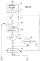
- FIG. 2 is a block diagram of the operations carried out by the panel 7 of the electronic system according to the present invention.
- the process starts with a block 100 capable of reading that the engine 4 has been turned on (KEY-ON); if the engine 4 starts, the process moves from block 100 to a block 110; otherwise, the system remains on hold.
- the block 110 initializes a variable L that describes the state of the lambda probe and the stoichiometric composition of the air/petrol mixture supplied to the engine; in particular, the probe state variable is set as: probe not failed not O.K.
- a varlable Str transition probe variable
- the block 120 is followed by a block 130 that reduces the variable T1 for each stroke of the engine.
- the block 130 is followed by a block 140 that compares the value of the variable T1 with a threshold value; if these valves are not equal, the system goes back from block 140 to block 130; otherwise it moves to a block 150.
- the block 150 sets the probe state variable as: probe not failed not O.K.
- the blocks 100-140 define a first system state known as the starting state.
- the system 1 remains in this state in order to obtain heating of the lambda probe and initialization of a number of variables of the system.
- the starting state is exited after a preset number of engine strokes (block 140), in other words at the end of a preset time after the engine 4 has been turned on and the lambda probe has warmed up.
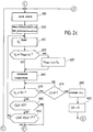
- the block 160 is followed by a block 170 in which the Vlambda voltage generated by the lambda probe is read.
- the block 170 is followed by a block 180 in which the Vlambda voltage value previously read is compared with the present value of the transition threshold variable Str; in particular, if the Vlambda voltage is greater than the transition threshold Str (Vlambda > Str), the system moves from block 180 to a block 190 (corresponding to a "rich" state detailed below); otherwise, it goes to a block 200 that reduces the content of the second counter.
- the block 200 is followed by a block 210 in which the Vlambda voltage value previously read is compared with a threshold that is substantially equal to zero; in particular, if the Vlambda voltage is substantially equal to zero, the system moves from block 210 to a block 220; otherwise, it goes to a block 230.
- the number of engine accelerations Nacc is checked; if the Nacc number is less than a calibration value, the system goes from block 220 to block 230; otherwise, it goes to a block 240 ("failure" state) that sets the lambda state variable as: probe not failed not O.K.
- the block 230 compares the value of the variable T2 with a threshold value; if these valves are not equal, the system goes back from block 230 to block 170; otherwise it goes to a block 250 (corresponding to a "lean" state detailed below) which sets the probe state variable as: not failed, O.K. lean.
- the blocks 150-230 define a second system state, known as the operational idle state.
- a first test is conducted on the voltage generated by the lambda probe (block 180) in order to identify a voltage higher than the transition threshold Str and corresponding to an air/petrol mixture which has more petrol than required by the stoichiometric ratio (rich state).
- a lambda probe malfunction situation is also identified, a situation due for example to a break in the connections between the panel 7 and the said lambda probe.
- This malfunction situation is identified if the voltage generated by the probe is substantially equal to zero (block 210), despite the fact that the engine has accelerated a preset number of times (block 220); in this case, the air/petrol mixture has shifted to the "rich" state and the failure to note this state is, therefore, an indication of a malfunction.
- Switchover from the optional idle state to the lean state (block 250) takes place if, after a preset number of engine strokes (block 230), a voltage higher than the threshold (block 180) is not read, or no malfunction of the type described above is found.
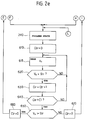
- the block 190 is followed by a block 300 in which a Vmax-ric variable is initialized, representing the maximum value of the voltage read on the lambda probe while it is in the "rich" state.
- a counter CNT_KO2 (not shown) is also initialized, the content of which is increased by a preset unit with each engine stroke.
- the block 300 is followed by a block 310 in which the Vlambda voltage generated by the lambda probe is read.
- the block 340 is followed by a block 370 in which the Vlambda voltage value previously noted is compared with the current value of the transition threshold variable Str; in particular, if the Vlambda voltage is lower than the transition threshold Str (Vlambda ⁇ Str), the system goes from block 370 to a block 375; otherwise, it goes to a block 380.
- the block 375 checks a variable Ctr which represents the number of transitions of state of the lambda probe; in particular, if the variable Ctr is equal to (or greater than) one, in other words, if there has been at least one transition from the rich state to the lean state, the system moves from block 375 to a block 390; otherwise, it returns to block 370.
- the block 400 is then followed by the "lean" state block 250 which sets the lambda probe state variable to: not failed, O.K. lean.
- a counter CNT_COFF of engine strokes that remain in cut-off is initialized; in particular, if the engine remains in the cut-off state for a preset number of strokes and the Vlambda voltage is over the threshold, the system goes from block 380 to block 240; otherwise, it goes to a block 430.
- the content of counter CNT_KO2 (not shown) is compared with a threshold value n; if the content of the counter matches this threshold value n, in other words, if n engine cycles have occurred since going into the rich state and there has been no changeover to the lean state, the system moves from block 430 to block 240 (failure state); otherwise, it returns to block 310.
- the blocks 190, 300-430 define a third system state known as the "rich" state; the system remains in this state when the air/petrol mixture has more petrol than required by the stoichiometric ratio.
- a test is periodically conducted (block 370) on the voltage generated by the lambda probe in order to identify a voltage below the transition threshold Str (corresponding to an air/petrol mixture that has less petrol than is required by the stoichiometric ratio) and to move to the lean state.
- Str transition threshold
- the transition threshold (block 390) is updated.
- the first malfunction situation is found (block 380) if the engine is in cut-off state (fuel supply interruption and, therefore, a necessarily "lean” mixture) and at the same time a Vlambda voltage above the threshold is found, corresponding in other words to a "rich” mixture fed to the engine.
- the second malfunction situation is found if, for n engine cycles in the rich state (block 430) no switchover to the lean state has occurred; in other words, if the system remains indefinitely in the rich state despite the reduction in the petrol percentage produced by block 340 (mixture thinning), it can be assumed that the switchover to the lean state was not recognized by the probe and that the probe has therefore failed.
- the block 250 is followed by a block 500 in which a Vmin-mag variable, representing the lowest voltage reading on the lambda probe while in the "lean" state, is initialized.
- a counter CNT_KO2 (not shown) is initialized in block 500, the content of this counter being increased by a preset unit with each engine stroke.
- the block 500 is followed by a block 510 in which the Vlambda voltage generated by the lambda probe is read.
- the block 540 is followed by a block 570 in which the Vlambda voltage value previously read is compared with the current value of the transition threshold variable Str; in particular, if the Vlambda voltage is greater than the transition threshold Str (Vlambda > Str), the system goes from block 570 to a block 575; otherwise, it goes to a block 580.
- variable Ctr is increased by one unit following the transition of state; the system then returns again from block 575 to block 190 (rich state).
- the content of the counter CNT_KO2 (not shown) is compared with a threshold value m; if the content of the counter matches this threshold value m, in other words, if m engine cycles have taken place since going into the rich state and there has been no switchover to the lean state, the system goes from block 580 to block 240 (failure state); otherwise, it returns to block 510.
- the blocks 250, 500-580 define a fourth system state known as the "lean" state; the system remains in this state when the air/petrol mixture has less petrol than required by the stoichiometric ratio.
- a test is periodically conducted (block 570) on the voltage generated by the lambda probe in order to identify a voltage greater than the transition threshold Str (corresponding to an air/petrol mixture with more petrol in it than required by the stoichiometric ratio) and to move to the "rich" state.
- Str transition threshold
- the transition threshold is not updated.
- the state variable L is set as: probe O.K. and failed.
- the block 610 is followed by a block 615 in which the Vlambda voltage generated by the probe is read.
- the block 615 is followed by a block 620 in which the system checks whether the Vlambda voltage passes through the threshold value; if not, it remains in idle and the system returns to block 615; otherwise, it goes to a block 630 which increases the variable Ctr by one unit following the transition.
- the block 630 is followed by a block 640 in which the content of the variable Ctr is compared with a threshold value C1; if the variable Ctr exceeds the threshold value C1, the system goes from block 640 to a block 650; otherwise, it returns to block 615.
- the value of the Vlambda voltage is compared with the current threshold value Vst; if the Vlambda voltage exceeds the Vst threshold, the system goes to a block 660, otherwise it goes to a block 670.
- the counter Ctr is reset to zero; also, the system goes from these blocks 660 and 670 to blocks 190 and 250, respectively.
- the blocks 240, 610-670 define a probe malfunction state (failure state).
- Exiting from the failure state is possible only after the lambda probe has switched over a preset number of times (block 640) after going into the failure state. Indeed, entry into the failure state occurs when the lambda probe continues to furnish the same value (high or low) constantly, despite the fact that the changed operating conditions of the engine indicate a switching of the signal from the probe. For this reason, when the probe starts switching again, this indicates that the probe has returned to normal operation.
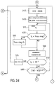
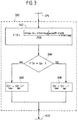
- Figure 3 illustrates in detall block 390 which updates the transition threshold Str.
- FTR transition fraction
- the block 392 is followed by a block 394 in which the transition function FTR thus calculated is compared with the transition threshold Str currently in use.
- transition function is greater than the transition threshold (FTR>Str)
- the system goes from block 394 to a block 396; otherwise (FTR ⁇ Str), it goes to a block 398.
- the block 340 is illustrated in detail with particular reference to Figure 4a.
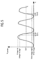
- the block 340 contains a first block 342 which reads the transition time Ttr1 ( Figure 5) taken by the decreasing voltage of the lambda probe 19 to go from a first and higher value equal to Vmaxric less a parameter sgl1, to a second value equal to the transition threshold Str.
- the block 342 is followed by a block 344 in which the transition time Ttr1 as previously calculated is compared with a threshold value t1; in particular, if the transition time Ttr1 is less than the threshold t1 (Tr1 ⁇ t1), the system goes from block 344 to a block 346; otherwise (Tr1>t1), it goes to a block 348.
- the block 346 sends control signals to the electronic panel 11 authorizing it to reduce gradually the percentage of petrol in the mixture, while block 348 sends control signals to the electronic panel 11 authorizing it to reduce quickly (fast thinning) the percentage of petrol in the mixture.
- the block 340 makes it possible to modulate the speed with which the percentage of petrol is decreased (thinning of the mixture) in the air/petrol mixture.
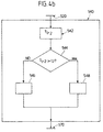
- the block 540 is illustrated in detail with particular reference to Figure 4b.
- the block 540 includes a first block 542 which reads the transition time Ttr2 taken by the rising voltage of the probe to go from a first and lower value equal to Vminmag plus a parameter sgl2, to a second value, equal to the transition threshold.
- the block 542 is followed by a block 544 in which the transition time Ttr2 as previously calculated is compared with a threshold value t2; in particular, if the transition time Ttr2 is greater than the threshold t2 (Tr2>t2), the system goes from block 544 to a block 548; otherwise (Tr2 ⁇ t2), it goes to a block 546.
- the block 546 sends control signals to the electronic panel 11 authorizing it to increase gradually the percentage of petrol in the mixture while block 548 sends control signals to the electronic panel 11 authorizing it to increase quickly the percentage of petrol in the mixture.
- the block 540 makes it possible to modulate the speed with which the percentage of petrol (mixture enrichment) is increased in the air/petrol mixture.
- the system uses a single transition threshold Str to search for the "rich” state and the "lean” state.
- the threshold is moreover "dynamic”, since it is periodically updated and adapted on the basis of the signal generated by the lambda probe.
- the system 1 makes it possible accurately to identify five different states (start, operational idle, rich, lean and failure), and to identify a number of malfunction situations.
- the system 1 also makes it possible to speed up an excessively slow "thinning” or "enrichment”.
Landscapes
- Engineering & Computer Science (AREA)
- Chemical & Material Sciences (AREA)
- Combustion & Propulsion (AREA)
- Mechanical Engineering (AREA)
- General Engineering & Computer Science (AREA)
- Analytical Chemistry (AREA)
- Electrical Control Of Air Or Fuel Supplied To Internal-Combustion Engine (AREA)
- Combined Controls Of Internal Combustion Engines (AREA)
- Measuring Oxygen Concentration In Cells (AREA)
Applications Claiming Priority (3)
| Application Number | Priority Date | Filing Date | Title |
|---|---|---|---|
| ITTO930857 | 1993-11-12 | ||
| ITTO930857A IT1261114B (it) | 1993-11-12 | 1993-11-12 | Sistema elettronico di calcolo del titolo miscela. |
| EP94117678A EP0657637B1 (de) | 1993-11-12 | 1994-11-09 | Elektronisches System zur Berechnung des Kraftstoff-Luftverhältnisses eines Verbrennungsmotors |
Related Parent Applications (1)
| Application Number | Title | Priority Date | Filing Date |
|---|---|---|---|
| EP94117678A Division EP0657637B1 (de) | 1993-11-12 | 1994-11-09 | Elektronisches System zur Berechnung des Kraftstoff-Luftverhältnisses eines Verbrennungsmotors |
Publications (3)
| Publication Number | Publication Date |
|---|---|
| EP0855498A2 true EP0855498A2 (de) | 1998-07-29 |
| EP0855498A3 EP0855498A3 (de) | 1998-08-26 |
| EP0855498B1 EP0855498B1 (de) | 2002-02-27 |
Family
ID=11411876
Family Applications (3)
| Application Number | Title | Priority Date | Filing Date |
|---|---|---|---|
| EP98105228A Expired - Lifetime EP0855498B1 (de) | 1993-11-12 | 1994-11-09 | Elektronisches Berechnungssystem der Gemischzusammensetzung |
| EP98105227A Expired - Lifetime EP0856653B1 (de) | 1993-11-12 | 1994-11-09 | Elektronisches Berechnungssystem der Gemischzusammensetzung |
| EP94117678A Expired - Lifetime EP0657637B1 (de) | 1993-11-12 | 1994-11-09 | Elektronisches System zur Berechnung des Kraftstoff-Luftverhältnisses eines Verbrennungsmotors |
Family Applications After (2)
| Application Number | Title | Priority Date | Filing Date |
|---|---|---|---|
| EP98105227A Expired - Lifetime EP0856653B1 (de) | 1993-11-12 | 1994-11-09 | Elektronisches Berechnungssystem der Gemischzusammensetzung |
| EP94117678A Expired - Lifetime EP0657637B1 (de) | 1993-11-12 | 1994-11-09 | Elektronisches System zur Berechnung des Kraftstoff-Luftverhältnisses eines Verbrennungsmotors |
Country Status (5)
| Country | Link |
|---|---|
| EP (3) | EP0855498B1 (de) |
| BR (1) | BR9404572A (de) |
| DE (3) | DE69430017T2 (de) |
| ES (3) | ES2172836T3 (de) |
| IT (1) | IT1261114B (de) |
Cited By (1)
| Publication number | Priority date | Publication date | Assignee | Title |
|---|---|---|---|---|
| GB2345341A (en) * | 1998-12-21 | 2000-07-05 | Ford Global Tech Inc | Diagnosing a lean air-fuel ratio |
Families Citing this family (1)
| Publication number | Priority date | Publication date | Assignee | Title |
|---|---|---|---|---|
| IT1285311B1 (it) * | 1996-03-12 | 1998-06-03 | Magneti Marelli Spa | Metodo di diagnosi dell'efficienza di un sensore di composizione stechiometrica dei gas di scarico posto a valle di un convertitore |
Family Cites Families (10)
| Publication number | Priority date | Publication date | Assignee | Title |
|---|---|---|---|---|
| JPS608328B2 (ja) * | 1979-05-31 | 1985-03-02 | 日産自動車株式会社 | 空燃比帰還制御装置 |
| JPS5713245A (en) * | 1980-06-30 | 1982-01-23 | Toyota Motor Corp | Method of controlling air fuel ratio of internal combustion engine |
| JPS5751936A (en) * | 1980-09-12 | 1982-03-27 | Hitachi Ltd | Controlling and trouble discrimination initializing timing setting system for engine controller |
| US4491921A (en) * | 1980-12-23 | 1985-01-01 | Toyota Jidosha Kogyo Kabushiki Kaisha | Method and apparatus for controlling the air fuel ratio in an internal combustion engine |
| JPS5830446A (ja) * | 1981-08-13 | 1983-02-22 | Honda Motor Co Ltd | 内燃エンジン用空燃比帰還制御装置の故障検出装置 |
| JPS58222939A (ja) * | 1982-05-28 | 1983-12-24 | Honda Motor Co Ltd | 内燃エンジンの酸素濃度検出系故障時の空燃比制御方法 |
| JPH0733790B2 (ja) * | 1985-12-11 | 1995-04-12 | 富士重工業株式会社 | 自動車用エンジンの空燃比制御装置 |
| JP2564510B2 (ja) * | 1985-12-25 | 1996-12-18 | 本田技研工業株式会社 | 内燃エンジンの排気ガス濃度センサの異常検出方法 |
| FR2592685B1 (fr) * | 1986-01-06 | 1989-12-29 | Renault | Procede de dosage de carburant pour moteur a combustion interne a injection electronique. |
| JPH03134240A (ja) * | 1989-10-18 | 1991-06-07 | Japan Electron Control Syst Co Ltd | 内燃機関の空燃比フィードバック制御装置 |
-
1993
- 1993-11-12 IT ITTO930857A patent/IT1261114B/it active IP Right Grant
-
1994
- 1994-11-09 EP EP98105228A patent/EP0855498B1/de not_active Expired - Lifetime
- 1994-11-09 EP EP98105227A patent/EP0856653B1/de not_active Expired - Lifetime
- 1994-11-09 ES ES98105228T patent/ES2172836T3/es not_active Expired - Lifetime
- 1994-11-09 DE DE69430017T patent/DE69430017T2/de not_active Expired - Fee Related
- 1994-11-09 DE DE69427199T patent/DE69427199T2/de not_active Expired - Fee Related
- 1994-11-09 ES ES98105227T patent/ES2158630T3/es not_active Expired - Lifetime
- 1994-11-09 ES ES94117678T patent/ES2125389T3/es not_active Expired - Lifetime
- 1994-11-09 EP EP94117678A patent/EP0657637B1/de not_active Expired - Lifetime
- 1994-11-09 DE DE69413784T patent/DE69413784T2/de not_active Expired - Fee Related
- 1994-11-10 BR BR9404572A patent/BR9404572A/pt not_active IP Right Cessation
Cited By (2)
| Publication number | Priority date | Publication date | Assignee | Title |
|---|---|---|---|---|
| GB2345341A (en) * | 1998-12-21 | 2000-07-05 | Ford Global Tech Inc | Diagnosing a lean air-fuel ratio |
| GB2345341B (en) * | 1998-12-21 | 2003-04-09 | Ford Global Tech Inc | Engine diagnostic method |
Also Published As
| Publication number | Publication date |
|---|---|
| EP0856653A3 (de) | 1998-08-26 |
| ITTO930857A0 (it) | 1993-11-12 |
| DE69430017T2 (de) | 2002-08-14 |
| ES2158630T3 (es) | 2001-09-01 |
| EP0856653B1 (de) | 2001-05-09 |
| DE69413784T2 (de) | 1999-02-25 |
| DE69427199T2 (de) | 2001-10-18 |
| BR9404572A (pt) | 1995-10-24 |
| EP0855498B1 (de) | 2002-02-27 |
| DE69427199D1 (de) | 2001-06-13 |
| ES2172836T3 (es) | 2002-10-01 |
| IT1261114B (it) | 1996-05-09 |
| ES2125389T3 (es) | 1999-03-01 |
| DE69430017D1 (de) | 2002-04-04 |
| EP0657637A2 (de) | 1995-06-14 |
| DE69413784D1 (de) | 1998-11-12 |
| EP0856653A2 (de) | 1998-08-05 |
| ITTO930857A1 (it) | 1995-05-12 |
| EP0657637B1 (de) | 1998-10-07 |
| EP0855498A3 (de) | 1998-08-26 |
| EP0657637A3 (de) | 1995-10-11 |
Similar Documents
| Publication | Publication Date | Title |
|---|---|---|
| US6351704B1 (en) | Method and apparatus for calibrating a position sensor used in engine control | |
| JP3161539B2 (ja) | 内燃機関の空燃比制御方法及び装置 | |
| JPH02185634A (ja) | アルコール内燃機関の空燃比制御装置 | |
| US4640254A (en) | Air-fuel ratio control system | |
| US6450145B2 (en) | Method and apparatus for fail-safe controlling internal combustion engine with electronic controlled throttle system | |
| JP3060745B2 (ja) | エンジンの空燃比制御装置 | |
| EP0855498B1 (de) | Elektronisches Berechnungssystem der Gemischzusammensetzung | |
| US20020083927A1 (en) | Method for controlling an internal combustion engine | |
| JPH01224433A (ja) | 内燃機関の空燃比制御装置 | |
| JPH05256175A (ja) | エンジンの排気センサの劣化検出装置 | |
| US5617836A (en) | Engine control system for producing and responding to an index of maturity of adaptive learing | |
| US20070079596A1 (en) | Apparatus and method for controlling air/fuel ratio of internal combustion engine | |
| US5586543A (en) | Mixture controller for an internal combustion engine | |
| JPH01232136A (ja) | エンジン制御装置 | |
| JPH08261042A (ja) | エンジンの空燃比制御装置 | |
| JPS5898637A (ja) | 内燃機関の空燃比制御装置 | |
| JP2536753B2 (ja) | エンジンの空燃比制御装置 | |
| JP4725481B2 (ja) | 空燃比制御装置 | |
| GB2346457A (en) | Air/fuel ratio control | |
| KR100222852B1 (ko) | 연료 분사 제어 방법 | |
| JP2007247452A (ja) | 硫黄被毒回復制御装置 | |
| KR20030075974A (ko) | 엘피아이 차량의 공연비 제어 방법 | |
| JP2001090598A (ja) | リニア空燃比センサ故障診断装置 | |
| KR100280001B1 (ko) | 엔진의 워밍업 구간중 연료량 보상 장치 | |
| JPH0526073A (ja) | 内燃機関の空燃比制御方法 |
Legal Events
| Date | Code | Title | Description |
|---|---|---|---|
| PUAI | Public reference made under article 153(3) epc to a published international application that has entered the european phase |
Free format text: ORIGINAL CODE: 0009012 |
|
| PUAL | Search report despatched |
Free format text: ORIGINAL CODE: 0009013 |
|
| AC | Divisional application: reference to earlier application |
Ref document number: 657637 Country of ref document: EP |
|
| AK | Designated contracting states |
Kind code of ref document: A2 Designated state(s): DE ES FR GB SE |
|
| AK | Designated contracting states |
Kind code of ref document: A3 Designated state(s): DE ES FR GB SE |
|
| 17P | Request for examination filed |
Effective date: 19980731 |
|
| 17Q | First examination report despatched |
Effective date: 20000126 |
|
| GRAG | Despatch of communication of intention to grant |
Free format text: ORIGINAL CODE: EPIDOS AGRA |
|
| GRAG | Despatch of communication of intention to grant |
Free format text: ORIGINAL CODE: EPIDOS AGRA |
|
| GRAH | Despatch of communication of intention to grant a patent |
Free format text: ORIGINAL CODE: EPIDOS IGRA |
|
| GRAH | Despatch of communication of intention to grant a patent |
Free format text: ORIGINAL CODE: EPIDOS IGRA |
|
| RAP1 | Party data changed (applicant data changed or rights of an application transferred) |
Owner name: MAGNETI MARELLI POWERTRAIN S.P.A. |
|
| REG | Reference to a national code |
Ref country code: GB Ref legal event code: IF02 |
|
| GRAA | (expected) grant |
Free format text: ORIGINAL CODE: 0009210 |
|
| AC | Divisional application: reference to earlier application |
Ref document number: 657637 Country of ref document: EP |
|
| AK | Designated contracting states |
Kind code of ref document: B1 Designated state(s): DE ES FR GB SE |
|
| REF | Corresponds to: |
Ref document number: 69430017 Country of ref document: DE Date of ref document: 20020404 |
|
| ET | Fr: translation filed | ||
| REG | Reference to a national code |
Ref country code: ES Ref legal event code: FG2A Ref document number: 2172836 Country of ref document: ES Kind code of ref document: T3 |
|
| PLBE | No opposition filed within time limit |
Free format text: ORIGINAL CODE: 0009261 |
|
| STAA | Information on the status of an ep patent application or granted ep patent |
Free format text: STATUS: NO OPPOSITION FILED WITHIN TIME LIMIT |
|
| 26N | No opposition filed |
Effective date: 20021128 |
|
| PGFP | Annual fee paid to national office [announced via postgrant information from national office to epo] |
Ref country code: DE Payment date: 20081127 Year of fee payment: 15 |
|
| PGFP | Annual fee paid to national office [announced via postgrant information from national office to epo] |
Ref country code: ES Payment date: 20081117 Year of fee payment: 15 |
|
| PGFP | Annual fee paid to national office [announced via postgrant information from national office to epo] |
Ref country code: SE Payment date: 20081112 Year of fee payment: 15 |
|
| PGFP | Annual fee paid to national office [announced via postgrant information from national office to epo] |
Ref country code: FR Payment date: 20080926 Year of fee payment: 15 |
|
| PGFP | Annual fee paid to national office [announced via postgrant information from national office to epo] |
Ref country code: GB Payment date: 20081117 Year of fee payment: 15 |
|
| EUG | Se: european patent has lapsed | ||
| GBPC | Gb: european patent ceased through non-payment of renewal fee |
Effective date: 20091109 |
|
| REG | Reference to a national code |
Ref country code: FR Ref legal event code: ST Effective date: 20100730 |
|
| PG25 | Lapsed in a contracting state [announced via postgrant information from national office to epo] |
Ref country code: FR Free format text: LAPSE BECAUSE OF NON-PAYMENT OF DUE FEES Effective date: 20091130 |
|
| PG25 | Lapsed in a contracting state [announced via postgrant information from national office to epo] |
Ref country code: DE Free format text: LAPSE BECAUSE OF NON-PAYMENT OF DUE FEES Effective date: 20100601 |
|
| PG25 | Lapsed in a contracting state [announced via postgrant information from national office to epo] |
Ref country code: GB Free format text: LAPSE BECAUSE OF NON-PAYMENT OF DUE FEES Effective date: 20091109 |
|
| REG | Reference to a national code |
Ref country code: ES Ref legal event code: FD2A Effective date: 20110304 |
|
| PG25 | Lapsed in a contracting state [announced via postgrant information from national office to epo] |
Ref country code: SE Free format text: LAPSE BECAUSE OF NON-PAYMENT OF DUE FEES Effective date: 20091110 |
|
| PG25 | Lapsed in a contracting state [announced via postgrant information from national office to epo] |
Ref country code: ES Free format text: LAPSE BECAUSE OF NON-PAYMENT OF DUE FEES Effective date: 20110303 |
|
| PG25 | Lapsed in a contracting state [announced via postgrant information from national office to epo] |
Ref country code: ES Free format text: LAPSE BECAUSE OF NON-PAYMENT OF DUE FEES Effective date: 20091110 |