EP0852678B1 - System zur schwingungsisolation, das einen passiv abgestimmten schwingungsdämpfer enthält - Google Patents
System zur schwingungsisolation, das einen passiv abgestimmten schwingungsdämpfer enthält Download PDFInfo
- Publication number
- EP0852678B1 EP0852678B1 EP96929778A EP96929778A EP0852678B1 EP 0852678 B1 EP0852678 B1 EP 0852678B1 EP 96929778 A EP96929778 A EP 96929778A EP 96929778 A EP96929778 A EP 96929778A EP 0852678 B1 EP0852678 B1 EP 0852678B1
- Authority
- EP
- European Patent Office
- Prior art keywords
- vibration absorber
- passive
- passive tuned
- isolation system
- tuned vibration
- Prior art date
- Legal status (The legal status is an assumption and is not a legal conclusion. Google has not performed a legal analysis and makes no representation as to the accuracy of the status listed.)
- Expired - Lifetime
Links
- 238000002955 isolation Methods 0.000 title claims description 42
- 239000006096 absorbing agent Substances 0.000 title claims description 30
- 229920001971 elastomer Polymers 0.000 claims description 51
- 239000000806 elastomer Substances 0.000 claims description 51
- 230000014759 maintenance of location Effects 0.000 claims description 7
- 230000033001 locomotion Effects 0.000 claims description 6
- 239000000463 material Substances 0.000 claims description 5
- 230000001747 exhibiting effect Effects 0.000 claims description 4
- 230000000717 retained effect Effects 0.000 claims description 2
- 238000013016 damping Methods 0.000 claims 1
- 229920001296 polysiloxane Polymers 0.000 claims 1
- 239000012530 fluid Substances 0.000 description 13
- 230000008901 benefit Effects 0.000 description 6
- 229910000831 Steel Inorganic materials 0.000 description 5
- 239000010959 steel Substances 0.000 description 5
- 244000043261 Hevea brasiliensis Species 0.000 description 4
- 229920003052 natural elastomer Polymers 0.000 description 4
- 229920001194 natural rubber Polymers 0.000 description 4
- 229920002379 silicone rubber Polymers 0.000 description 3
- 235000012431 wafers Nutrition 0.000 description 3
- 239000005062 Polybutadiene Substances 0.000 description 2
- 229910052782 aluminium Inorganic materials 0.000 description 2
- XAGFODPZIPBFFR-UHFFFAOYSA-N aluminium Chemical compound [Al] XAGFODPZIPBFFR-UHFFFAOYSA-N 0.000 description 2
- 210000002969 egg yolk Anatomy 0.000 description 2
- 238000009434 installation Methods 0.000 description 2
- 229910052751 metal Inorganic materials 0.000 description 2
- 239000002184 metal Substances 0.000 description 2
- 239000000203 mixture Substances 0.000 description 2
- 229920002857 polybutadiene Polymers 0.000 description 2
- 238000009420 retrofitting Methods 0.000 description 2
- 229920003051 synthetic elastomer Polymers 0.000 description 2
- 239000004677 Nylon Substances 0.000 description 1
- 239000004809 Teflon Substances 0.000 description 1
- 229920006362 Teflon® Polymers 0.000 description 1
- 230000009471 action Effects 0.000 description 1
- 230000003044 adaptive effect Effects 0.000 description 1
- 239000000956 alloy Substances 0.000 description 1
- 229910045601 alloy Inorganic materials 0.000 description 1
- 238000005452 bending Methods 0.000 description 1
- 230000005540 biological transmission Effects 0.000 description 1
- 238000010276 construction Methods 0.000 description 1
- 230000000694 effects Effects 0.000 description 1
- 239000002783 friction material Substances 0.000 description 1
- 230000007246 mechanism Effects 0.000 description 1
- 238000000034 method Methods 0.000 description 1
- 230000004048 modification Effects 0.000 description 1
- 238000012986 modification Methods 0.000 description 1
- 229920001778 nylon Polymers 0.000 description 1
- 230000008569 process Effects 0.000 description 1
- 239000010935 stainless steel Substances 0.000 description 1
- 229910001220 stainless steel Inorganic materials 0.000 description 1
- 230000003068 static effect Effects 0.000 description 1
- WFKWXMTUELFFGS-UHFFFAOYSA-N tungsten Chemical compound [W] WFKWXMTUELFFGS-UHFFFAOYSA-N 0.000 description 1
- 229910052721 tungsten Inorganic materials 0.000 description 1
- 239000010937 tungsten Substances 0.000 description 1
- UONOETXJSWQNOL-UHFFFAOYSA-N tungsten carbide Chemical compound [W+]#[C-] UONOETXJSWQNOL-UHFFFAOYSA-N 0.000 description 1
- 238000003466 welding Methods 0.000 description 1
Images

Classifications
-
- F—MECHANICAL ENGINEERING; LIGHTING; HEATING; WEAPONS; BLASTING
- F16—ENGINEERING ELEMENTS AND UNITS; GENERAL MEASURES FOR PRODUCING AND MAINTAINING EFFECTIVE FUNCTIONING OF MACHINES OR INSTALLATIONS; THERMAL INSULATION IN GENERAL
- F16F—SPRINGS; SHOCK-ABSORBERS; MEANS FOR DAMPING VIBRATION
- F16F1/00—Springs
- F16F1/36—Springs made of rubber or other material having high internal friction, e.g. thermoplastic elastomers
- F16F1/38—Springs made of rubber or other material having high internal friction, e.g. thermoplastic elastomers with a sleeve of elastic material between a rigid outer sleeve and a rigid inner sleeve or pin, i.e. bushing-type
- F16F1/3807—Springs made of rubber or other material having high internal friction, e.g. thermoplastic elastomers with a sleeve of elastic material between a rigid outer sleeve and a rigid inner sleeve or pin, i.e. bushing-type characterised by adaptations for particular modes of stressing
- F16F1/3814—Springs made of rubber or other material having high internal friction, e.g. thermoplastic elastomers with a sleeve of elastic material between a rigid outer sleeve and a rigid inner sleeve or pin, i.e. bushing-type characterised by adaptations for particular modes of stressing characterised by adaptations to counter axial forces
-
- B—PERFORMING OPERATIONS; TRANSPORTING
- B64—AIRCRAFT; AVIATION; COSMONAUTICS
- B64D—EQUIPMENT FOR FITTING IN OR TO AIRCRAFT; FLIGHT SUITS; PARACHUTES; ARRANGEMENT OR MOUNTING OF POWER PLANTS OR PROPULSION TRANSMISSIONS IN AIRCRAFT
- B64D27/00—Arrangement or mounting of power plants in aircraft; Aircraft characterised by the type or position of power plants
- B64D27/40—Arrangements for mounting power plants in aircraft
- B64D27/402—Arrangements for mounting power plants in aircraft comprising box like supporting frames, e.g. pylons or arrangements for embracing the power plant
-
- F—MECHANICAL ENGINEERING; LIGHTING; HEATING; WEAPONS; BLASTING
- F16—ENGINEERING ELEMENTS AND UNITS; GENERAL MEASURES FOR PRODUCING AND MAINTAINING EFFECTIVE FUNCTIONING OF MACHINES OR INSTALLATIONS; THERMAL INSULATION IN GENERAL
- F16F—SPRINGS; SHOCK-ABSORBERS; MEANS FOR DAMPING VIBRATION
- F16F7/00—Vibration-dampers; Shock-absorbers
- F16F7/10—Vibration-dampers; Shock-absorbers using inertia effect
- F16F7/104—Vibration-dampers; Shock-absorbers using inertia effect the inertia member being resiliently mounted
- F16F7/108—Vibration-dampers; Shock-absorbers using inertia effect the inertia member being resiliently mounted on plastics springs
-
- Y—GENERAL TAGGING OF NEW TECHNOLOGICAL DEVELOPMENTS; GENERAL TAGGING OF CROSS-SECTIONAL TECHNOLOGIES SPANNING OVER SEVERAL SECTIONS OF THE IPC; TECHNICAL SUBJECTS COVERED BY FORMER USPC CROSS-REFERENCE ART COLLECTIONS [XRACs] AND DIGESTS
- Y02—TECHNOLOGIES OR APPLICATIONS FOR MITIGATION OR ADAPTATION AGAINST CLIMATE CHANGE
- Y02T—CLIMATE CHANGE MITIGATION TECHNOLOGIES RELATED TO TRANSPORTATION
- Y02T50/00—Aeronautics or air transport
- Y02T50/40—Weight reduction
Definitions
- the present invention relates to a vibration isolation system for reducing vibration transmitted from a vibrating member into a support structure. Specifically, the invention relates to an isolation system including a passive tuned vibration absorber for reducing vibration transmission at a specific frequency or within a frequency range.
- Elastomeric engine mounts are known for attaching an engine to structure.
- Commonly assigned US Patent Nos. 4,805,851 to Herbst entitled “Turbine Engine Mounting Bracket Assembly”, 5,108,045 to Law et al. entitled “Engine Mounting Assembly”, 5,176,339 to Schmidt entitled “Resilient Pivot Type Aircraft Mounting”, and 5,351,930 to Gwinn entitled “Mountings for Engines and the Like” all describe engine mounting systems for attaching a vibrating engine to structure. Notably, however, these systems have the drawback that when they are attached to soft (low stiffness) structures, the mounts can be somewhat ineffective.
- a mount otherwise referred to as an isolator, must have a very rigid structure to act against.
- Fluid mounts which utilize fluid inertia to create amplified fluid inertia forces are also known for attaching a vibrating member to a structure.
- US-A-4403762 on which the preamble of claim 1 is based, describes an isolation system including an elastomeric mount having an outer member with means for attachment to a vibrating member; an inner member within the outer member and having means for attachment to a structure; and a flexible elastomer section interconnected between said outer and inner members thereby allowing relative movement and isolating vibrations there between for reducing a vibration transmitted from the vibrating member to an operating frequency f o and a passive tuned vibration exhibiting a resonant frequency f r and including:
- the present invention is a vibration isolation system including, in combination, an elastomer mount and a passive elastomer tuned vibration absorber (TVA) located proximate thereto for reducing vibration that is transmitted from a vibrating member such as an engine into a structure at a predetermined operating frequency or within a limited operating frequency range.
- the system comprises an elastomeric mount which includes an outer member and means for attaching the outer member to the vibrating member, an inner member and means for attaching the inner member to the structure, and a flexible elastomeric section interconnected therebetween.
- the flexible elastomer section accommodates relative movement between the inner member and outer member and acts as a primary isolator.
- the passive TVA exhibits a resonant frequency f r and is preferably attached directly to the inner member of the elastomeric mount on the structure side thereof or alternatively to the structure proximate said elastomeric mount at a point where it will be effective.
- the passive TVA includes a tuning mass, a rigid member disposed adjacent the tuning mass, and an elastomeric spring interconnected between the rigid member and the tuning mass, said elastomer spring and said tuning mass being selected such that the resonant frequency f r of the spring-mass system is slightly less than said operating frequency f o and in particular, it is desired that f r /f o be in the range of between 0.90 and 0.99.
- the TVA is directly attached and clamped to the structure in the proximity of the elastomeric mounting.
- isolation system that it allows effective isolation when incorporating a mount attached to a soft structure.
- the TVAs include fail-safe features.
- a TVA assembly may be retrofitted to an existing structure by clamping across and through the structure.
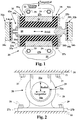
- FIG. 1 is shown an isolation system 20 particularly useful for reducing dynamic vibration transmitted between a vibrating member 22 such as an engine, and a supporting structure 24 (Fig. 2) such as an aircraft yolk, spar or beam structure.
- the isolation system 20 is most effective at a predetermined operating frequency f o and is also effective within a narrow range about f o .
- f o would coincide with the cruise frequency of an aircraft engine. It is desired that the range of isolation would encompass normal variations about cruise such as during takeoff and landing maneuvers.
- the isolation system 20 is used where a vibrating member 22 attaches to a relatively soft structure.
- the isolation system 20 is described with reference to aircraft systems, it should be understood that the isolation system combining an elastomer mount and a TVA will apply where any vibrating member is attached to a soft structure.
- the isolation system 20 is comprised of the combination of an elastomeric mount 25 and at least one passive elastomeric tuned vibration absorber (TVA).
- TVA passive elastomeric tuned vibration absorber
- the elastomeric mount 25 preferably includes an outer member 26 for attachment to the vibrating member 22, an inner member 28 for interconnection to the structure 24 (Fig.
- a flexible elastomer section 30 which is preferably a natural rubber or a blend of synthetic elastomer such as polybutadiene and natural rubber, but could be a silicone elastomer or the like if higher temperatures or highly resonant conditions dictate.
- the flexible elastomer section 30 causes a flexible interconnection between the inner member 28 and outer member 26 and allows relative movement, such as axial, radial or tangential, therebetween.
- the elastomeric mount 25 acts as a primary isolator between the structure 24 and the vibrating member 22 to initially isolate vibrations transmitted from the vibrating member 22 to the structure 24.
- the relative movement between the inner member 28 and outer member 26 is accommodated in the tangential, radial (into and out of the paper), and axial directions.
- Means for attaching the outer member 26 to the vibrating member 22 may include flanges 27a and 27b and fasteners 29 or the like.
- Means for attaching the inner member 28 to the structure 24 may include clevis portions 23a and 23b, base plate 21 ( Fig. 2 ) and fasteners 31 ( Fig. 2 ). It should be understood the inner member could attach to the vibrating member and the outer member to the structure with the passive TVA attached to the structure side and still fall within the scope of the appended claims.
- the isolation system 20 also includes at least one passive TVA attached to structure 24 proximate the elastomeric mount 25.
- the term proximate preferably encompasses direct interconnection to the structure 24 at the location of the inner member 28 as shown in the Fig. 1 embodiment, as well as attachment to the structure 24 at a point on the structure 24 where the TVA will be effective (See Fig. 4a).
- the allowable attachment points for effective location of the passive TVA will depend on the stiffness or flexibility of the structure 24. Typically, the softer or more flexible the structure 24, the closer in proximity the TVA will have to be placed to the elastomeric mount 25.
- the passive TVA is tuned such that it exhibits a resonant frequency f r which is tuned such it occurs slightly below the most common operating frequency f o .
- the ratio of f r /f o be in the range of between about 0.90 and 0.99 for systems having transmissibility at resonance of between about 5 and 15 (tan delta (otherwise known as the loss factor) of between about 0.067 and 0.2).
- twin, passive, and matched resonant frequency TVAs are used, 32a and 32b which are interconnected and clamped to the structure 24 by attaching directly to the inner member 28 which extends through the elastomeric mount 25.
- the passive TVAs, 32a and 32b, and inner member 28 make up the passive TVA assembly 43a. It is notable that the TVA assembly 43a clamps the elastomer mount 25 to the clevis portions 23a and 23b causing a direct interconnection to the structure 24.
- the passive TVAs 32a and 32b both include tuning masses 34a and 34b manufactured from steel or other high density material such as tungsten or tungsten carbide alloy, rigid members 38a and 38b, preferably manufactured from steel, aluminum or the like, disposed adjacent the tuning mass 34a and 34b , and springs 36a and 36b, which are natural rubber, a blend of natural rubber and synthetic elastomer such as polybutadiene, or silicone elastomer and are interconnected between the substantially parallel surfaces of the rigid members 38a and 38b and tuning masses 34a and 34b.
- the springs 36a and 36b be integrally bonded and operate in pure shear between substantially parallel surfaces of the rigid members 38a and 38b and the tuning masses 34a and 34b.
- the springs 36a and 36b in this case, shear elastomer sections are placed in pure shear upon encountering vibration of the structure 24 which excites the tuning masses 34a and 34b and causes them to resonate.
- the shear elastomer section of the passive TVAs 32a and 32b are oriented such that any absorber action generated thereby, i.e., the inertial forces are applied both tangentially and/or radially to the vibrating member 22.
- the material used for the springs 36a and 36b have a loss factor (tan delta) of between 0.067 and 0.2 and, more preferably about 0.10, and exhibit a dynamic shear modulus of between about 50 psi (344 kPa) and 100 psi (689 kPa) (at G10/10 at 10 hz and 10% strain) with a preferred dynamic shear modulus of about 75 psi (517 kPa).
- the tuning masses 34a and 34b are puck-like and manufactured from stainless steel. It should be understood that rigid members 38a and 38b may be separate units which attach to the inner member 28 or be manufactured as part of the inner member 28 as shown on the right side of the inner member 28 of Fig. 1.
- the elastomeric mount 25 shown in Fig. 1 includes two half sections 33a and 33b which are bushing-like center-bonded mounts and received within a cylindrical or tapered bore 35 formed in outer member 26. Included in each half section, 33a and 33b, are inner sleeves 39a and 39b, which are preferably manufactured from steel, and elastomer bushes 37a and 37b. Each elastomer bush, 37a and 37b, is preferably integrally bonded through known bonding processes to the outer surface of inner sleeves 39a and 39b. Flexible elastomer section 30 is formed by elastomer bushes 37a and 37b being inserted in bore 35. Typically, assembly will apply a small amount of precompression to the elastomer mount 25, and thus, to the elastomer bushes 37a and 37b, both radially and axially.
- Fig. 2 illustrates an end view of the isolation system 20.
- the clevis portions 23a and 23b (Fig. 1) attach to the base plate 21 by welding or other attachment means such as bolting.
- Base plate 21 attaches directly to structure 24 by fasteners 31.
- the plane of operation of the passive TVA 32a is perpendicular to the axial axis of the elastomeric mount 25.
- the passive TVAs 32a and 32b act to provide inertia forces in the radial and tangential directions to suppress vibration in both these directions.
- the TVAs, 32a and 32b preferably include a thin sandwich-type elastomer section comprising the flexible elastomer section 36a and 36b.
- the thickness t of the elastomer section falls in the range of between about 0.015 inch (0.381 mm) and 0.045 inch (1.143 mm) and preferably has a constant thickness within the layer of about 0.03 inch (0.762 mm).
- the ratio of f r /f o is about 0.94.
- a silicone elastomer having a tan delta of about 0.10 would be used for aircraft systems that are subject to significant temperature variations or resonant conditions.
- This type of TVA assembly 43a would be effective on a soft structure having a dynamic radial structural stiffness of about between 25,000 lbf./in. (4,378,150 N/m) and 100,000 lbf./in. (17,512,600 N/m). This range would be considered a soft structure for a small commercial fixed wing aircraft, i.e., business jet applications.
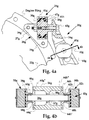
- Fig. 3a illustrates a passive TVA assembly 43c for attachment to a structure 24c in the proximity of the elastomeric mount (not shown).
- the structure 24c may be a box-beam type shown, an I-beam (Fig. 4b), or the like.
- the passive TVA assembly 43c comprises two passive TVAs 32c and 32d which are interconnected by inner member 28c which acts as the means for clamping the passive TVA assembly 43c directly to, and preferably through, the structure 24c in the proximity of the elastomeric mount (not shown).
- the passive TVA assembly 43c preferably includes clamping plates 46c and 46d to distribute the clamping loads over the surface of the structure 24c.
- the clamping plates 46c and 46d may be steel, aluminum or the like. Wrench slots (see Fig.
- a passive TVA assembly 43c which clamps through the structure 24c has the advantage of reducing the bending moments imparted on the structure 24c as compared to beam like TVAs that bolt into a threaded hole formed in the structure. Moreover, it allows for retrofitting of the passive TVA on systems which already incorporate an elastomeric mount.
- the passive TVAs 32c and 32d include rigid members 38c and 38d which have coiled threads 50c and 50d inserted therein.
- the coiled threads 50c and 50d are preferably self-locking threaded inserts.
- Wafers 54c and 54d attach to masses 34c and 34d by way of fastening means such as screws 56c and 56d shown, and act as adjustment masses to finely tune the resonant frequency f r of the passive TVA assembly 43c.
- Wafers 54c and 54d are preferably manufactured by stamping from a steel plate. Alternatively, wafers 54c and 54d could be glued to ends of masses 34c and 34d.
- Sleeve 58c inserts in the through bores 57c and 57d formed in structure 24c. Bores 57c and 57d may be lightening holes already formed in the structure 24c, or may be added to the existing structure to accommodate the passive TVA assembly 43c. Sleeve 58c serves as means for taking up play and acts as a bushing-like element for properly aligning the passive TVA assembly 43c relative to the structure 24c. Sleeve 58c is preferably manufactured from a nylon, Teflon or other low-friction material or it could be metal as well. The inner member 28c is inserted through the structure 24c and passive TVAs 32c and 32d are threaded and secured onto the ends thereof.
- clamping plates 46c and 46d exert a clamping force on the surface of structure 24c to rigidly fasten the passive TVA assembly 43c to the structure 24c. In this way, any inertia forces generated by the passive TVAs 32c and 32d are directly transferred to the structure 24c to suppress vibration of the structure 24c or increase the impedance of the structure 24 and make it appear dynamically stiff to the elastomer mount.
- Fig. 3b illustrates another embodiment of passive TVA assembly 43e wherein the passive TVAs 32e and 32f are attached directly to the inner member 28e by way of retention bolts 60e and 60f.
- the TVA's 32e and 32f clamp the structure to the mount 25e inserting through bore 42e and by clamping clevis portions 23e and 23f to the elastomer mount 25e.
- the inner member 28e would be made up of the threaded member 28e and inner sleeves 39e and 39f.
- the retention bolts 60e and 60f retain the masses 34e and 34f should the elastomer bond separate between the masses 34e and 34f and rigid members 38e and 38f.
- the head of the retention bolts 60e and 60f provide fail-safe retention by being larger than the bore in the passive TVA masses 34e and 34f. This fail-safe retention prevents masses 34e and 34f from falling into the engine compartment in aircraft applications.
- the elastomeric mount 25e is similar to that described in Fig. 1. The difference is that the elastomer mount 25e includes tapered conical sections and laminated elastomer-and-shim construction. This elastomer mount is available from Lord Corporation as part number LM-420-SA5-1.
- Fig. 4a illustrates another embodiment of isolation system 20g which includes, in combination, an elastomeric mount 25g and passive TVA assembly 43g including at least one passive TVA 32g and preferably two passive TVAs.
- Passive TVA 32g and preferable passive TVA assembly 43g are located in the proximity of elastomeric mount 25g. Where the passive TVA 32g is located, as well as the stiffness of the structure, will determine the TVA effectiveness.
- the passive TVA 32g is most effective when attached to the inner member at the location of the elastomeric mount 25g. However, if the passive TVA 32g must be attached to the structure 24g at some other location other than at the elastomeric mount 25g, as in the Fig. 4a embodiment, then the passive TVA 32g should be placed as proximate as possible to the elastomeric mount 25g but on the structure side thereof. The degree of proximity will be described with reference to Fig. 5.
- the elastomeric mounting 25g in this Fig. 4a embodiment includes an outer member 26g for attaching to the engine ring of a vibrating member 22g by fasteners 29g, an inner member 28g for attaching to the I-beam structure 24g and a flexible elastomer section 30g which is a tube form-type elastomer section.
- the elastomer mount 25g is slipped into position between two adjacent engine rings.
- Flange 27g attaches to one engine ring by fasteners 29g and a mirror image of the half section attaches to the other adjacent engine ring (not shown) in a similar fashion.
- Outer sleeves 41g and 41h are bonded to flexible elastomer section 30g and are retained within the confines of the pocket formed in the outer member 26g by threaded ring 67g which threads into the outer member 26g.
- Inner member 28g is bonded to flexible elastomer section 30g and is attached to I-beam structure 24g by way of fastener 65g shown.
- the TVA assembly 43g clamps to the structure 24g in such a fashion as to allow retrofitting of the TVA assembly 43g onto existing structures and systems which already include mounts. In particular, the TVA assembly 43g will clamp to the structure 24g in the proximity of the elastomer mount 25g through a lightening hole such as 64g shown. The TVA assembly 43g is actually clamped though a smaller lightening hole adjacent to lightening hole 64g.
- Fig. 4b illustrates a partial cross-sectional side view of the passive TVA assembly 43g shown attached to the I-beam like structure 24g.
- the passive TVA assembly 43g includes passive TVAs 32g and 32h securely attached to inner member 28g which has threads formed on the ends thereof. Wrench slots 62g and 62h help the installer torque the assembly properly. Hexes may alternatively be formed on the shafts of rigid members 38g and 38h.
- a sleeve 58g is installed into the structure 24g to accommodate and align the passive TVA assembly 43g and prevent metal-to-metal contact between the inner member 28g and the structure 24g.
- the bore 57g is preferably a lightening or weight-reducing hole formed in the structure 24g thereby requiring no modification to the structure 24g to install the passive TVA assembly 43g.
- Clamping members 46g and 46h may have slots 64g', 64g" and 64h', 64h" formed thereon for being received within the I-section of the I-beam and preventing rotation of the TVA assembly 43g relative to the structure 24g once properly torqued. Proper torquing will apply enough force to the I-beam structure 24g to clamp the TVA assembly 43g to the structure 24g through the through bore 57g formed therein.
- Locking threaded inserts prevent the TVAs 32g and 32h from unscrewing from the inner member 28g. Further, lock washers 68g and 68h may be used to add additional locking or used as the primary locking mechanism.
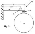
- Fig. 5 illustrates a schematic side view of an isolation system 20j.
- the structure 24j is a beam-like structure, as are most aircraft installations, having a length L
- the passive TVA 32j is only approximately 50% effective as compared to when it is placed on the end of the beam 24j. Therefore, it is desired to place the TVA 32j at or beyond 0.8 L proximate the elastomer mount 25j.
- the mount dynamic stiffness and the structure dynamic stiffness be approximately equal in magnitude for optimal effectiveness of the TVA 32j .
- the present invention provides a novel isolation system which includes, in combination, an elastomeric mount and at least one passive TVA, and preferably a passive TVA assembly, located in the proximity of said elastomeric mount for providing improved isolation at an operating frequency or within a narrow operating frequency range.
- the elastomeric mount includes an inner member for connecting to the structure, an outer member for connecting to a vibrating member such as an engine, and a flexible elastomer section forming a flexible interconnection therebetween.
- the passive TVA includes a tuning mass, a rigid member, and an elastomer spring therebetween.
- the passive TVA's resonant frequency f r is tuned to a frequency just below the predominant operating frequency f o and preferably fr/fo is between about 0.99 and 0.90.
- the passive elastomer TVA is attached directly to the inner member of the elastomeric mount, but may, alternatively, be attached to the flexible structure at a point where it will be effective by clamping thereto.
- the isolation system has the key advantage of allowing an elastomeric mount to be much more effective when attaching to a soft structure, whereas, prior art systems had limited effectiveness when so attached.
Landscapes
- Engineering & Computer Science (AREA)
- General Engineering & Computer Science (AREA)
- Mechanical Engineering (AREA)
- Aviation & Aerospace Engineering (AREA)
- Health & Medical Sciences (AREA)
- Child & Adolescent Psychology (AREA)
- Vibration Prevention Devices (AREA)
- Springs (AREA)
Claims (11)
- System zur Schwingungsisolation (20 etc.) mit einer elastomeren Halterung (25 etc.), welche folgendes umfaßt, ein äußeres Element (26 etc.) mit Mitteln zum Befestigen eines Vibrationselementes (22 etc.); ein inneres Element (28 etc.) innerhalb des äußeren Elements mit Mitteln zum Befestigen eines Aufbaus (23 etc., 24 etc.); und einen flexiblen elastomeren Abschnitt (30 etc.), welcher zwischen dem inneren und äußeren Element angeordnet ist, wodurch eine Relativbewegung und Vibrationsisolation zur Reduktion der von dem Vibrationselement übertragenden Vibrationen bei einer Betriebsfrequenz f0 oder innerhalb eines engen Frequenzbereiches um f0 erzielt ist, wobei ferner ein passiv abgestimmter Vibrationsabsorber (32 etc.) vorgesehen ist, welcher eine Resonanzfrequenz aufweist und folgendes umfaßt:(i) ein freigängiges Abstimmgewicht (34 etc.) mit einer vorbestimmten Masse;(ii) ein starres Element (38 etc.), welches benachbart zum Abstimmgewicht angeordnet ist;(iii) eine elastomere Feder (36 etc.) mit einer vorbestimmten Steifheit, welche zwischen dem starren Element (38 etc.) und dem Abstimmgewicht (34 etc.) angeordnet ist, dadurch gekennzeichnet, daß die Steifheit der elastomeren Feder und die vorbestimmte Masse des Abstimmgewichts derart gewählt ist, daß sich eine Resonanzfrequenz fr des passiv abgestimmten Vibrationsabsorbers ergibt, wobei diese Resonanzfrequenz fr derart abgestimmt ist, daß diese Resonanzfrequenz fr kleiner als die Betriebsfrequenz f0 ist und ein Verhältnis von fr/f0 im Bereich zwischen 0,90 und 0,99 liegt und daß der passiv abgestimmte Vibrationsabsorber (32 etc.) an einem Ort nahe der elastomeren Halterung (25 etc.) mit dem Aufbau (23 etc., 24 etc.) verbunden und an diesen geklammert ist.
- System zur Schwingungsisolation (20 etc.) nach Anspruch 1, dadurch gekennzeichnet, daß der passiv abgestimmte Vibrationsabsorber (32 etc.) mit dem inneren Element (28 etc.) der elastomeren Halterung (25 etc.) mittels einer Verschraubung auf dieser verbunden ist, was ein Klammern des passiv abgestimmten Vibrationsabsorbers an dem Aufbau (23 etc.) bedingt und ebenso die elastomere Halterung mit dem Aufbau verbindet.
- System zur Schwingungsisolation (20 etc.) nach Anspruch 1, dadurch gekennzeichnet, daß ein erster passiv abgestimmter Vibrationsabsorber (32 etc.) und ein zweiter passiv abgestimmter Vibrationsabsorber (32 etc.) mit dem Aufbau nahe der elastomeren Halterung verbunden sind, wobei der erste und zweite passiv abgestimmte Vibrationsabsorber derart abgestimmte sind, daß sie eine im wesentlichen gleiche Resonanzfrequenz fr aufweisen.
- System zur Schwingungsisolation (20 etc.) nach Anspruch 1, dadurch gekennzeichnet, daß der passiv abgestimmte Vibrationsabsorber (32 etc.) mit dem Aufbau nahe der elastomeren Halterung verbunden ist, wobei der Aufbau (23 etc., 24 etc.) eine niedrige strukturelle Steifheit unter etwa 17.512.600 Nm-1 (100,000 lb./in) aufweist.
- System zur Schwingungsisolation (20 etc.) nach Anspruch 1, dadurch gekennzeichnet, daß die elastomere Feder (36 etc.) des passiv abgestimmten Vibrationsabsorbers durch die einwirkenden Kräfte hauptsächlich einer reinen Scherlast unterliegt und daß das freigängige Abstimmgewicht (34 etc.) im wesentlichen scheibenförmig ausgebildet ist.
- System zur Schwingungsisolation (20 etc.) nach Anspruch 1, dadurch gekennzeichnet, daß der passiv abgestimmte Vibrationsabsorber (32 etc.) innerhalb einer passiv abgestimmten Vibrationsabsorberanordnung (43 etc.) angeordnet ist, welche zwei angepaßte, passiv abgestimmte Vibrationsabsorber umfaßt, wobei die passiv abgestimmte Vibrationsabsorberanordnung mittels einer Durchgangsbohrung (42 etc., 57 etc., 64 etc.) mit dem Aufbau verklammert ist, wobei die Durchgangsbohrung an einem Ort nahe der elastomeren Halterung in dem Aufbau ausgebildet ist.
- System zur Schwingungsisolation (20 etc.) nach Anspruch 6, dadurch gekennzeichnet, daß die in dem Aufbau ausgebildete Durchgangsbohrung ein Erleichterungsloch (64 etc.) ist.
- System zur Schwingungsisolation (20 etc.) nach Anspruch 1, dadurch gekennzeichnet, daß das freigängige Abstimmgewicht (34 etc.) des passiv abgestimmten Vibrationsabsorbers (32 etc.) durch einen Sicherungsbolzen (60 etc.) zurückgehalten ist, welcher derart an dem inneren Element befestigt ist, daß er eine fehlfunktionssichere Verbindung herstellt.
- System zur Schwingungsisolation (20 etc.) nach Anspruch 1, dadurch gekennzeichnet, daß der passiv abgestimmte Vibrationsabsorber (32 etc.) innerhalb einer passiv abgestimmten Vibrationsabsorberanordnung (43 etc.) angeordnet ist, welche zwei angepaßte, passiv abgestimmte Vibrationsabsorber umfaßt und wobei die passiv abgestimmte Vibrationsabsorberanordnung an einer balkenartigen Struktur (24 etc.) befestigt ist, welche eine Balkenlänge L aufweist, wobei der passiv abgestimmte Vibrationsabsorber an einem Punkt innerhalb der letzten 20% der Balkenlänge L benachbart zur elastomeren Halterung (25 etc.) angeordnet ist.
- System zur Schwingungsisolation (20 etc.) nach Anspruch 1, dadurch gekennzeichnet, daß die elastomere Feder (36 etc.) aus einem Silikonwerkstoff mit einem Dämpfungsverlustfaktor im Bereich zwischen etwa 0,067 und 0,20 hergestellt ist.
- System zur Schwingungsisolation (20 etc.) nach Anspruch 1, dadurch gekennzeichnet, daß der flexible, elastomere Abschnitt (30 etc.) der elastomeren Halterung einen elastomeren Laufbüchsenabschnitt oder einen elastomeren, rohrförmigen Abschnitt umfaßt.
Applications Claiming Priority (3)
| Application Number | Priority Date | Filing Date | Title |
|---|---|---|---|
| US08/533,824 US5687948A (en) | 1995-09-26 | 1995-09-26 | Vibration isolation system including a passive tuned vibration absorber |
| US533824 | 1995-09-26 | ||
| PCT/US1996/013852 WO1997012160A1 (en) | 1995-09-26 | 1996-08-30 | Vibration isolation system including a passive tuned vibration absorber |
Publications (2)
| Publication Number | Publication Date |
|---|---|
| EP0852678A1 EP0852678A1 (de) | 1998-07-15 |
| EP0852678B1 true EP0852678B1 (de) | 2001-06-13 |
Family
ID=24127583
Family Applications (1)
| Application Number | Title | Priority Date | Filing Date |
|---|---|---|---|
| EP96929778A Expired - Lifetime EP0852678B1 (de) | 1995-09-26 | 1996-08-30 | System zur schwingungsisolation, das einen passiv abgestimmten schwingungsdämpfer enthält |
Country Status (6)
| Country | Link |
|---|---|
| US (1) | US5687948A (de) |
| EP (1) | EP0852678B1 (de) |
| BR (1) | BR9610616A (de) |
| DE (1) | DE69613382T2 (de) |
| ES (1) | ES2159754T3 (de) |
| WO (1) | WO1997012160A1 (de) |
Families Citing this family (69)
| Publication number | Priority date | Publication date | Assignee | Title |
|---|---|---|---|---|
| US6002778A (en) * | 1996-08-07 | 1999-12-14 | Lord Corporation | Active structural control system and method including active vibration absorbers (AVAS) |
| US6065742A (en) * | 1996-09-13 | 2000-05-23 | Lord Corporation | Multi-directional tuned vibration absorber |
| US6095460A (en) * | 1996-10-23 | 2000-08-01 | Freightliner Corporation | Exhaust system support arrangement |
| US5855260A (en) * | 1996-12-13 | 1999-01-05 | The Aerospace Corporation | Tuned broadband particulate vibration absorber |
| US6442021B1 (en) * | 1998-06-15 | 2002-08-27 | Compaq Computer Corporation | Hot-pluggable disk carrier having enhanced rotational drive vibration control capability |
| GB2339263B (en) * | 1998-07-08 | 2002-07-17 | Draftex Ind Ltd | Restraining link |
| US6328293B1 (en) | 1998-09-18 | 2001-12-11 | Lord Corporation | Multi-linkage suspension system including outboard isolators |
| US6189830B1 (en) | 1999-02-26 | 2001-02-20 | The Boeing Company | Tuned engine mounting system for jet aircraft |
| DE10007051A1 (de) * | 2000-02-17 | 2001-11-08 | Volkswagen Ag | Elastische Aufhängung, vorzugsweise für eine Abgasanlage |
| US6634862B2 (en) | 2000-09-15 | 2003-10-21 | General Dynamics Advanced Information Systems, Inc. | Hydraulic actuator |
| US20020094274A1 (en) * | 2000-09-15 | 2002-07-18 | Terpay Gregory Weston | Passive device for noise reduction |
| US6644590B2 (en) | 2000-09-15 | 2003-11-11 | General Dynamics Advanced Information Systems, Inc. | Active system and method for vibration and noise reduction |
| US6416016B1 (en) * | 2000-09-15 | 2002-07-09 | Sikorsky Aircraft Corporation | Actuator for an active transmission mount isolation system |
| US6267361B1 (en) | 2000-09-21 | 2001-07-31 | Carrier Vibrating Equipment, Inc. | Dynamic reaction reducer for isolated vibratory equipment |
| FR2829525B1 (fr) * | 2001-09-13 | 2004-03-12 | Snecma Moteurs | Assemblage de secteurs d'un distributeur de turbine a un carter |
| US6641121B1 (en) | 2002-01-03 | 2003-11-04 | Meritor Light Vehicle Technology, Llc | Damping structure |
| US6722677B2 (en) | 2002-01-04 | 2004-04-20 | Meritor Light Vehicle Technology, Llc | Connecting component |
| ATE494214T1 (de) * | 2002-07-01 | 2011-01-15 | Barry Controls Corp | Zwei-ton schwingungsdämpfer |
| ATE422228T1 (de) | 2003-12-23 | 2009-02-15 | Suspensiones Elasticas Del Nor | Schwingungsisolierender dämpfer |
| JP4465202B2 (ja) * | 2004-02-06 | 2010-05-19 | Hoya株式会社 | モータの制振取付構造 |
| JP4270502B2 (ja) * | 2004-02-13 | 2009-06-03 | 東海ゴム工業株式会社 | エンジンマウント |
| WO2007001373A2 (en) * | 2004-09-17 | 2007-01-04 | Aurora Flight Sciences | Inbound transition control for a trail-sitting vertical take off and landing aircraft |
| US8001764B2 (en) | 2004-09-17 | 2011-08-23 | Aurora Flight Sciences Corporation | Vibration isolation engine mount system and method for ducted fans |
| US7364115B2 (en) * | 2004-09-17 | 2008-04-29 | Aurora Flight Sciences Corporation | System and method for controlling engine RPM of a ducted fan aircraft |
| WO2007001372A2 (en) | 2004-09-17 | 2007-01-04 | Aurora Flight Sciences | Ducted spinner for engine cooling |
| US7441724B2 (en) | 2004-09-17 | 2008-10-28 | Aurora Flight Sciences Corporation | System and method for controlling a roll rate of a torsionally-disconnected freewing aircraft |
| WO2006037096A2 (en) * | 2004-09-28 | 2006-04-06 | Cooper-Standard Automotive Inc. | One-piece outer split shell pre-compressed cradle/sub-frame mount |
| GB0506990D0 (en) | 2005-04-06 | 2005-05-11 | Bae Systems Plc | Vibration isolation |
| US8104736B2 (en) * | 2005-12-01 | 2012-01-31 | Hamilton Sundstrand Corporation | Gas turbine engine auxiliary component mount |
| FR2917711B1 (fr) * | 2007-06-25 | 2010-01-15 | Snecma | Suspension d'un turbomoteur a la structure d'un aeronef |
| US7967282B2 (en) * | 2008-10-23 | 2011-06-28 | Honeywell International Inc. | Vibration isolators |
| US9527598B2 (en) * | 2009-01-26 | 2016-12-27 | Lord Corporation | Aircraft engine mounting system and method of mounting aircraft engines |
| US7784773B1 (en) | 2009-08-04 | 2010-08-31 | Itt Manufacturing Enterprises, Inc. | Isolator useful for in-line mounting with a strut |
| US8511601B2 (en) * | 2009-10-01 | 2013-08-20 | Hawker Beechcraft Corp. | Aircraft with tuned vibration absorber mounted on skin |
| US20110079477A1 (en) * | 2009-10-01 | 2011-04-07 | Indranil Dandaroy | Tuned vibration absorber mountable to aircraft skin panel |
| FR2968053B1 (fr) * | 2010-11-26 | 2013-08-23 | Hutchinson | Dispositif de controle vibratoire actif, vehicule comportant un tel dispositif et chape active pour un tel dispositif. |
| DE102011009191A1 (de) * | 2011-01-21 | 2012-07-26 | Eads Deutschland Gmbh | Vorrichtung zur Schwingungsdämpfung in einer Struktur |
| WO2012142103A2 (en) * | 2011-04-11 | 2012-10-18 | Trelleborg Automotive Usa, Inc. | Method of producing split outer shell cradle mount with rate plates |
| CN102267569B (zh) * | 2011-05-10 | 2013-12-04 | 北京航空航天大学 | 一种用于小型无人直升机的悬浮式发动机连接装置 |
| US9388875B2 (en) | 2011-10-18 | 2016-07-12 | The Boeing Company | Aeroelastic tuned mass damper |
| US8882089B2 (en) | 2012-08-17 | 2014-11-11 | Itt Manufacturing Enterprises Llc | Dual radius isolator |
| JP6354231B2 (ja) * | 2014-03-19 | 2018-07-11 | 三菱自動車工業株式会社 | ブッシュ装置 |
| DE102015116799A1 (de) * | 2015-10-02 | 2017-04-06 | Benteler Automobiltechnik Gmbh | Fahrwerkslager |
| CN105952845A (zh) * | 2016-06-28 | 2016-09-21 | 无锡市锡山区羊尖镇锦达商业设备厂 | 一种稳固效果更好的飞轮 |
| EP3573890B1 (de) | 2016-12-20 | 2023-07-19 | Bombardier Inc. | Schubglied mit abgestimmtem absorber |
| US10576813B2 (en) * | 2017-08-14 | 2020-03-03 | Ford Global Technologies, Llc | Mounting bracket for a vehicle component and method of forming |
| CA3080178C (en) * | 2018-01-15 | 2022-09-20 | Lord Corporation | Engine mount system and elements for reduced force transmission and reduced static motion and associated methods |
| GB201805838D0 (en) * | 2018-04-09 | 2018-05-23 | Dtr Vms Ltd | Bush |
| US11738614B2 (en) * | 2018-04-30 | 2023-08-29 | Research & Manufacturing Corporation Of America | Two-piece vertical control arm bushing |
| US11187296B2 (en) | 2018-11-29 | 2021-11-30 | Raytheon Company | Tuned mass absorber assembly and system for attenuating frequency specific vibrational energy |
| CN109838490A (zh) * | 2019-01-30 | 2019-06-04 | 河海大学常州校区 | 一种橡胶隔振装置 |
| CN109695651A (zh) * | 2019-01-30 | 2019-04-30 | 河海大学常州校区 | 一种橡胶隔振装置 |
| CN109654150A (zh) * | 2019-01-30 | 2019-04-19 | 河海大学常州校区 | 一种橡胶隔振装置 |
| DE102019104386A1 (de) * | 2019-02-21 | 2020-08-27 | Vibracoustic Ag | Schwingungstilger |
| EP3946175A4 (de) * | 2019-04-05 | 2022-12-21 | Stabilife LLC | Am körper tragbare vorrichtung zur behandlung von tremor |
| DE102019005092B4 (de) * | 2019-07-22 | 2022-05-12 | Sumitomo Riko Company Limited | Schwingungstilger und Verfahren zum Herstellen eines Schwingungstilgers |
| US11274722B2 (en) * | 2019-07-24 | 2022-03-15 | The Boeing Company | Damping apparatus and associated systems and methods for damping a first member relative to a second member |
| US11215255B2 (en) * | 2019-07-25 | 2022-01-04 | Textron Innovations, Inc. | Two-mode tuned vibration absorber |
| US11486460B2 (en) * | 2019-08-27 | 2022-11-01 | Deere & Company | Work vehicle with tuned mass dampers |
| WO2021126186A1 (en) * | 2019-12-18 | 2021-06-24 | Lord Corporation | Ultra-high temperature elastomeric alignment & isolation devices |
| US11027605B1 (en) | 2020-03-19 | 2021-06-08 | Douglas D. Myers | Vibration attenuating engine mounting apparatus |
| US11168789B2 (en) | 2020-04-07 | 2021-11-09 | Douglas D. Myers | High-volume diaphragm securement apparatus |
| JP7444765B2 (ja) * | 2020-06-22 | 2024-03-06 | 株式会社プロスパイラ | 防振装置用ブラケット |
| FR3117996A1 (fr) * | 2020-12-17 | 2022-06-24 | Airbus Operations | Partie d’aéronef comportant un dispositif de liaison entre deux structures |
| CN113409753B (zh) * | 2021-05-19 | 2023-12-15 | 华南理工大学 | 一种多层薄膜型声学超材料结构及其设计方法 |
| US20230061308A1 (en) * | 2021-08-31 | 2023-03-02 | Richard Alan Manwell | Multi-chamber internally damped tuned vibration absorber |
| US12319419B2 (en) | 2023-09-25 | 2025-06-03 | General Electric Company | Fluid-filled thrust link apparatus and associated method |
| US12529323B2 (en) | 2023-09-25 | 2026-01-20 | General Electric Company | Variable diameter thrust link apparatus |
| US12509999B2 (en) | 2023-09-25 | 2025-12-30 | General Electric Company | Viscous damper apparatus and associated methods to control a response to a resonant vibration frequency |
Family Cites Families (41)
| Publication number | Priority date | Publication date | Assignee | Title |
|---|---|---|---|---|
| US1819665A (en) * | 1930-01-08 | 1931-08-18 | Vibrachek Company | Vibration reducing device |
| US3487888A (en) * | 1966-08-22 | 1970-01-06 | Mc Donnell Douglas Corp | Cabin engine sound suppressor |
| US3490556A (en) * | 1968-01-15 | 1970-01-20 | Mc Donnell Douglas Corp | Aircraft cabin noise reduction system with tuned vibration absorbers |
| US4088042A (en) * | 1976-09-07 | 1978-05-09 | The Boeing Company | Vibration isolation system |
| US4150588A (en) * | 1976-12-29 | 1979-04-24 | Brewer Engineering Laboratories, Inc. | Dynamic vibration absorber |
| US4230291A (en) * | 1978-06-07 | 1980-10-28 | United Technologies Corporation | Tuned spring-mass vibration absorber |
| EP0006819B1 (de) * | 1978-07-03 | 1984-06-27 | Automobiles Peugeot | Aufhängungsvorrichtung insbesondere für Fahrzeugmotor |
| FR2447776A1 (fr) * | 1979-02-02 | 1980-08-29 | Berthiez | Perfectionnements apportes aux machines-outils munies d'un outil porte par un bras porte-outil |
| EP0015378B1 (de) * | 1979-03-01 | 1984-04-25 | Messerschmitt-Bölkow-Blohm Gesellschaft mit beschränkter Haftung | Schwingungsisolator |
| US4372431A (en) * | 1979-11-05 | 1983-02-08 | The Boeing Company | Six axis vibration isolation system |
| JPS56108307A (en) * | 1980-02-01 | 1981-08-27 | Nissan Motor Co Ltd | Device for supporting engine |
| JPS6015808B2 (ja) * | 1980-04-17 | 1985-04-22 | 日産自動車株式会社 | エンジンのマウンテイング装置 |
| JPS6015807B2 (ja) * | 1980-04-17 | 1985-04-22 | 日産自動車株式会社 | エンジンのマウンテイング装置 |
| JPS594264B2 (ja) * | 1980-06-27 | 1984-01-28 | 南舘 誠 | 振動抑制型のハンドル装置 |
| US4456213A (en) * | 1980-09-24 | 1984-06-26 | Nissan Motor Company, Limited | Engine mounting structure |
| US4405101A (en) * | 1980-10-29 | 1983-09-20 | United Technologies Corp. | Vibration isolation system |
| US4403762A (en) * | 1981-02-20 | 1983-09-13 | General Motors Corporation | Low force transmissibility mount |
| JPS6014627A (ja) * | 1983-07-06 | 1985-01-25 | Nissan Motor Co Ltd | サスペンションメンバの筒状弾性ブッシュ |
| US4514458A (en) * | 1983-11-09 | 1985-04-30 | Lord Corporation | Spring-like material formed of compressed metallic wire |
| US4634081A (en) * | 1983-12-30 | 1987-01-06 | The Boeing Company | Aft engine mount with vibration isolators |
| DE3443029C2 (de) * | 1984-11-26 | 1986-10-02 | Metzeler Kautschuk GmbH, 8000 München | Elastisches Motorlager |
| JPH0315870Y2 (de) * | 1985-10-18 | 1991-04-05 | ||
| US4811919A (en) * | 1987-08-06 | 1989-03-14 | Lord Corporation | Volume compensated fluid mount |
| US4805851A (en) * | 1987-08-10 | 1989-02-21 | Herbst Paul T | Turbine engine mounting bracket assembly |
| FR2629545B1 (fr) * | 1988-03-30 | 1993-02-19 | Aerospatiale | Contre-fiche elastique a resonateur hydro-mecanique integre notamment pour la suspension d'une boite de transmission sur un giravion et dispositif de suspension en comportant application |
| JPH0630500Y2 (ja) * | 1988-07-29 | 1994-08-17 | サンデン株式会社 | 車輌用空調装置用圧縮機の振動低減装置 |
| US5433422A (en) * | 1988-09-02 | 1995-07-18 | Ross; Colin F. | Active vibration control through sensing and controlling forces on an intermediate body |
| US5118051A (en) * | 1989-04-18 | 1992-06-02 | United Technologies Corporation | Roll vibration absorber |
| US5065959A (en) * | 1989-11-21 | 1991-11-19 | The Boeing Company | Vibration damping aircraft engine attachment |
| US5127498A (en) * | 1990-01-16 | 1992-07-07 | Massachusetts Institute Of Technology | Impedance matches mass damper |
| US5108045A (en) * | 1990-04-25 | 1992-04-28 | Law Thomas R | Engine mounting assembly |
| US5197692A (en) * | 1991-05-29 | 1993-03-30 | Lord Corporation | Adaptive fluid mount |
| US5127607A (en) * | 1991-07-09 | 1992-07-07 | Lord Corporation | Fluid torque-restraint system with optimized fluid expansion |
| US5388811A (en) * | 1991-07-09 | 1995-02-14 | Lord Corporation | Torque-control system for vehicles cabs and the like |
| US5176339A (en) * | 1991-09-30 | 1993-01-05 | Lord Corporation | Resilient pivot type aircraft mounting |
| US5174552A (en) * | 1991-10-15 | 1992-12-29 | Lord Corporation | Fluid mount with active vibration control |
| GB9125011D0 (en) * | 1991-11-25 | 1992-01-22 | Rolls Royce Plc | A mounting arrangement for a gas turbine engine |
| IT1256769B (it) * | 1992-01-21 | 1995-12-15 | Istituto Per Le Ricerche Di Te | Smorzatore dinamico di vibrazioni bifrequenziale. |
| US5351930A (en) * | 1992-08-11 | 1994-10-04 | Lord Corporation | Mounting for engines and the like |
| US5374039A (en) * | 1992-08-24 | 1994-12-20 | Lord Corporation | Fluid-and-elastomer support device |
| US5413320A (en) * | 1993-06-17 | 1995-05-09 | Lord Corporation | Fluid mount for devices such as engines |
-
1995
- 1995-09-26 US US08/533,824 patent/US5687948A/en not_active Expired - Lifetime
-
1996
- 1996-08-30 DE DE69613382T patent/DE69613382T2/de not_active Expired - Fee Related
- 1996-08-30 BR BR9610616A patent/BR9610616A/pt not_active IP Right Cessation
- 1996-08-30 WO PCT/US1996/013852 patent/WO1997012160A1/en not_active Ceased
- 1996-08-30 EP EP96929778A patent/EP0852678B1/de not_active Expired - Lifetime
- 1996-08-30 ES ES96929778T patent/ES2159754T3/es not_active Expired - Lifetime
Also Published As
| Publication number | Publication date |
|---|---|
| WO1997012160A1 (en) | 1997-04-03 |
| US5687948A (en) | 1997-11-18 |
| DE69613382T2 (de) | 2002-05-02 |
| DE69613382D1 (de) | 2001-07-19 |
| ES2159754T3 (es) | 2001-10-16 |
| BR9610616A (pt) | 1999-04-06 |
| EP0852678A1 (de) | 1998-07-15 |
Similar Documents
| Publication | Publication Date | Title |
|---|---|---|
| EP0852678B1 (de) | System zur schwingungsisolation, das einen passiv abgestimmten schwingungsdämpfer enthält | |
| US6065742A (en) | Multi-directional tuned vibration absorber | |
| EP0927314B1 (de) | Schwingungenisolierungseinsatz für flugzeugboden und dergleichen | |
| EP1296082B1 (de) | Dynamisch optimisiertes Motoraufhängungssystem | |
| WO2000017049A1 (en) | Multi-linkage suspension system including outboard isolators | |
| US5592814A (en) | Attaching brittle composite structures in gas turbine engines for resiliently accommodating thermal expansion | |
| EP1290354B1 (de) | Schwingungsisolator | |
| WO1997020705A1 (en) | Auxiliary damper for rubber suspension mountings | |
| US6012680A (en) | Passive lateral vibration isolation system for a spacecraft launch vehicle | |
| US6676116B2 (en) | Elastomeric suspension and mounting system | |
| US10227892B2 (en) | Fuel flow divider valve mounting arrangement for a gas turbine engine | |
| US20070108340A1 (en) | Vibration isolation system | |
| US8511601B2 (en) | Aircraft with tuned vibration absorber mounted on skin | |
| EP3295052B1 (de) | Dämpfungsvorrichtungen, systeme und verfahren für hohlwellen, streben und balken mit biegemodi | |
| JP2004034978A (ja) | アイソレータアセンブリ | |
| JPS5946323A (ja) | 内燃機関とトランスミツシヨンを含む配列装置 | |
| US20060043654A1 (en) | Energy-managing mounts | |
| US8960598B2 (en) | System for attaching an impeller engine | |
| US20110079477A1 (en) | Tuned vibration absorber mountable to aircraft skin panel | |
| RU2254506C2 (ru) | Листовая рессорная опора | |
| JPS6170242A (ja) | 動的吸振器 | |
| CA2244991A1 (en) | Dynamically optimized engine suspension system |
Legal Events
| Date | Code | Title | Description |
|---|---|---|---|
| PUAI | Public reference made under article 153(3) epc to a published international application that has entered the european phase |
Free format text: ORIGINAL CODE: 0009012 |
|
| 17P | Request for examination filed |
Effective date: 19980316 |
|
| AK | Designated contracting states |
Kind code of ref document: A1 Designated state(s): CH DE ES FR GB LI SE |
|
| 17Q | First examination report despatched |
Effective date: 19980709 |
|
| GRAG | Despatch of communication of intention to grant |
Free format text: ORIGINAL CODE: EPIDOS AGRA |
|
| GRAG | Despatch of communication of intention to grant |
Free format text: ORIGINAL CODE: EPIDOS AGRA |
|
| GRAH | Despatch of communication of intention to grant a patent |
Free format text: ORIGINAL CODE: EPIDOS IGRA |
|
| GRAH | Despatch of communication of intention to grant a patent |
Free format text: ORIGINAL CODE: EPIDOS IGRA |
|
| GRAA | (expected) grant |
Free format text: ORIGINAL CODE: 0009210 |
|
| AK | Designated contracting states |
Kind code of ref document: B1 Designated state(s): CH DE ES FR GB LI SE |
|
| REF | Corresponds to: |
Ref document number: 69613382 Country of ref document: DE Date of ref document: 20010719 |
|
| REG | Reference to a national code |
Ref country code: CH Ref legal event code: NV Representative=s name: MOINAS & SAVOYE SA |
|
| REG | Reference to a national code |
Ref country code: ES Ref legal event code: FG2A Ref document number: 2159754 Country of ref document: ES Kind code of ref document: T3 |
|
| ET | Fr: translation filed | ||
| REG | Reference to a national code |
Ref country code: GB Ref legal event code: IF02 |
|
| PLBE | No opposition filed within time limit |
Free format text: ORIGINAL CODE: 0009261 |
|
| STAA | Information on the status of an ep patent application or granted ep patent |
Free format text: STATUS: NO OPPOSITION FILED WITHIN TIME LIMIT |
|
| 26N | No opposition filed | ||
| PGFP | Annual fee paid to national office [announced via postgrant information from national office to epo] |
Ref country code: SE Payment date: 20030821 Year of fee payment: 8 |
|
| PGFP | Annual fee paid to national office [announced via postgrant information from national office to epo] |
Ref country code: CH Payment date: 20030825 Year of fee payment: 8 |
|
| PGFP | Annual fee paid to national office [announced via postgrant information from national office to epo] |
Ref country code: GB Payment date: 20030827 Year of fee payment: 8 |
|
| PGFP | Annual fee paid to national office [announced via postgrant information from national office to epo] |
Ref country code: ES Payment date: 20030908 Year of fee payment: 8 |
|
| PG25 | Lapsed in a contracting state [announced via postgrant information from national office to epo] |
Ref country code: GB Free format text: LAPSE BECAUSE OF NON-PAYMENT OF DUE FEES Effective date: 20040830 |
|
| PG25 | Lapsed in a contracting state [announced via postgrant information from national office to epo] |
Ref country code: SE Free format text: LAPSE BECAUSE OF NON-PAYMENT OF DUE FEES Effective date: 20040831 Ref country code: LI Free format text: LAPSE BECAUSE OF NON-PAYMENT OF DUE FEES Effective date: 20040831 Ref country code: ES Free format text: LAPSE BECAUSE OF NON-PAYMENT OF DUE FEES Effective date: 20040831 Ref country code: CH Free format text: LAPSE BECAUSE OF NON-PAYMENT OF DUE FEES Effective date: 20040831 |
|
| PGFP | Annual fee paid to national office [announced via postgrant information from national office to epo] |
Ref country code: DE Payment date: 20040930 Year of fee payment: 9 |
|
| EUG | Se: european patent has lapsed | ||
| REG | Reference to a national code |
Ref country code: CH Ref legal event code: PL |
|
| GBPC | Gb: european patent ceased through non-payment of renewal fee |
Effective date: 20040830 |
|
| REG | Reference to a national code |
Ref country code: ES Ref legal event code: FD2A Effective date: 20040831 |
|
| PG25 | Lapsed in a contracting state [announced via postgrant information from national office to epo] |
Ref country code: DE Free format text: LAPSE BECAUSE OF NON-PAYMENT OF DUE FEES Effective date: 20060301 |
|
| REG | Reference to a national code |
Ref country code: FR Ref legal event code: PLFP Year of fee payment: 20 |
|
| PGFP | Annual fee paid to national office [announced via postgrant information from national office to epo] |
Ref country code: FR Payment date: 20150629 Year of fee payment: 20 |