EP0852317B1 - Backrohr mit einem Lufteinlass und einer Heizelementanordung - Google Patents
Backrohr mit einem Lufteinlass und einer Heizelementanordung Download PDFInfo
- Publication number
- EP0852317B1 EP0852317B1 EP19980105610 EP98105610A EP0852317B1 EP 0852317 B1 EP0852317 B1 EP 0852317B1 EP 19980105610 EP19980105610 EP 19980105610 EP 98105610 A EP98105610 A EP 98105610A EP 0852317 B1 EP0852317 B1 EP 0852317B1
- Authority
- EP
- European Patent Office
- Prior art keywords
- heating element
- cooking chamber
- air
- film heating
- air passage
- Prior art date
- Legal status (The legal status is an assumption and is not a legal conclusion. Google has not performed a legal analysis and makes no representation as to the accuracy of the status listed.)
- Expired - Lifetime
Links
- 238000010438 heat treatment Methods 0.000 title claims description 50
- 238000010411 cooking Methods 0.000 title claims 13
- 239000002241 glass-ceramic Substances 0.000 claims description 6
- 239000002184 metal Substances 0.000 claims description 6
- 239000000919 ceramic Substances 0.000 claims description 3
- 239000011521 glass Substances 0.000 claims description 3
- 239000010408 film Substances 0.000 description 27
- 238000010276 construction Methods 0.000 description 2
- 239000010409 thin film Substances 0.000 description 2
- 238000006555 catalytic reaction Methods 0.000 description 1
- 239000012777 electrically insulating material Substances 0.000 description 1
- 238000005516 engineering process Methods 0.000 description 1
- 230000005855 radiation Effects 0.000 description 1
- 239000002470 thermal conductor Substances 0.000 description 1
Images
Classifications
-
- F—MECHANICAL ENGINEERING; LIGHTING; HEATING; WEAPONS; BLASTING
- F24—HEATING; RANGES; VENTILATING
- F24C—DOMESTIC STOVES OR RANGES ; DETAILS OF DOMESTIC STOVES OR RANGES, OF GENERAL APPLICATION
- F24C15/00—Details
- F24C15/32—Arrangements of ducts for hot gases, e.g. in or around baking ovens
- F24C15/322—Arrangements of ducts for hot gases, e.g. in or around baking ovens with forced circulation
- F24C15/325—Arrangements of ducts for hot gases, e.g. in or around baking ovens with forced circulation electrically-heated
Definitions
- the present invention relates to an oven with an air inlet according to the preamble of claim 1.
- the air outlet may be the above-mentioned suction opening act for air from the oven, but above Outlet openings for the air back into the oven. Becomes air introduced from the environment into the oven, it acts the passage mentioned is again a hot air inlet to the oven.
- the air passage mentioned is provided on the back of the oven and preferably formed as an air inlet for air from the oven, wherein further preferably the passage openings have a circular shape Define air outlet area.
- the air passage is again circular and is divided by several, each by arcuate slits formed defined sectors, wherein at least two film heating elements connected in parallel provided on intermediate bridges in at least one sector are.
- the film heating element provided according to the invention can at the air outlet transversely and / or in the air inlet direction be arranged.
- Carrier sections are preferably made of glass, glass ceramic, ceramic or enamelled metal, preferably made of glass ceramic or enamelled metal to use as heat radiation elements to work with the highest possible heat conduction.
- the film heating element is preferably a Thin or thick film heating element, preferably around a thick film element.
- the film heating element provided on a removable carrier, preferably with electrical plug contacts.
- the air outlet as an air inlet formed from the oven and operatively connected to a blower, which distributes the air drawn in through the air inlet leads back into the oven.
- the film heating element according to the invention When used on an air outlet where, as from the oven, steam and vapor contaminated air it is further, because of the small space requirement, possible, the film heating element according to the invention in the flow shadow to arrange the air mentioned and thereby his Minimize pollution, which is reinforced by catalysis becomes.
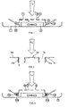
- a first embodiment of the invention is shown schematically.
- a blower 3 is arranged on the rear wall of an oven 1.
- an air inlet 5 formed by a plurality of inlet openings 7 with intermediate webs 9, the schematically illustrated film heating element arrangement 11 is applied, preferably in the flow shadow of the sucked-in air L e .
- the blower 3 blows the air heated in the air inlet area by means of the film heating element 11 from the oven 1 back into the oven, via air outlets 13, optionally with baffle arrangements 15 resulting in a desired air flow distribution.
- FIG. 2 shows schematically and enlarged an air passage 5a with openings 7a and intermediate webs 9a, in which the film of the heating element 11a provided according to the invention with a film plane E in the flow direction corresponding to L e of the air flow.
- FIGS. 1 (11) and 2 (11a) As shown in broken lines at 11 in FIG. 2, it is straightforward possible, the embodiments according to FIGS. 1 (11) and 2 (11a) to combine, from which it can be seen that with the inventive proposed film heating element an optimal Possibility is created, available volumes anyway optimal use for heating the air.
- FIG. 3 starting from a representation according to FIG. 1, another Embodiment shown, in which, as is readily apparent, the flowing air in the area of the air outlets 13 is heated according to the invention with the film heating element 11b, and it can be seen that the embodiments according to FIG. 1 and FIG. 3 may be combined with FIG. 2 or as desired can be combined.
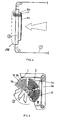
- FIG. 4 shows an embodiment variant which is preferably used today of the oven according to the invention.
- the blower 3 is mounted on the rear wall of the oven tube muffle 1 ', 5, is an air inlet plate 5b arranged.
- At the air inlet plate 5b is a circular one Air inlet 15 incorporated, defined by arcuate Slots 7b, which define several opening sectors I, II, etc.
- arcuate Slots 7b which define several opening sectors I, II, etc.
- the film heating element according to the invention 11c On the webs lying between the arcuate slots 7b 9b runs, meandering, the film heating element according to the invention 11c, along two of those through the arcuate slots 7b defined circle sectors as shown along the Sectors II and III.
- Heating element 11c also only along one of the sectors can be provided, and that per sector or at least for a certain proportion of the envisaged sectors a heating element 11c is provided. These are connected in parallel.
- the film heating element 11c shows electrical connections 17 on the plate 5b, preferably plug connections.
- the heating element 11c according to the invention is preferably not, as shown in Fig. 5 for reasons of clarity, on the provided the side of the passage opening facing the baking chamber, but, as shown schematically in Fig. 1, on the Back.
- the carrier at least in the present case the flat surface 19 of the plate 5b, made of a good thermal conductor and electrically insulating material, so made of ceramic, Glass, glass ceramic or enamelled metal, preferably made of Glass ceramic or enameled metal.
- a good thermal conductor and electrically insulating material so made of ceramic, Glass, glass ceramic or enamelled metal, preferably made of Glass ceramic or enameled metal.
- the inventive Film heating element is as thin film or, and preferably, as Thick film heating element formed.
- blowers 3 as dashed lines in Fig. 4 entered at 3a, also outside of the oven 1 defining muffle. Even with this version become film heating elements at the air outlet from the oven and / or provided at the air inlet in the oven.
Landscapes
- Engineering & Computer Science (AREA)
- Chemical & Material Sciences (AREA)
- Combustion & Propulsion (AREA)
- Mechanical Engineering (AREA)
- General Engineering & Computer Science (AREA)
- Electric Stoves And Ranges (AREA)
- Direct Air Heating By Heater Or Combustion Gas (AREA)
Description
- Fig. 1
- schematisch eine erste Ausführungsvariante eines erfindungsgemässen Backrohres;
- Fig. 2
- an einem beispielsweise gemäss Fig. 1 vorgesehenen Luftdurchlass, zwei weitere Ausführungsvarianten des Heizelementes, in unterschiedlicher Ausrichtung bezüglich Luftströmungsrichtung;
- Fig. 3
- ausgehend von einer Darstellung gemäss Fig. 1, die erfindungsgemässe Heizelementanordnung Luftauslass-seitig;
- Fig. 4
- vereinfacht, im Querschnitt, eine heute bevorzugte Ausführungsvariante des erfindungsgemässen Backrohres, und
- Fig. 5
- die Aufsicht auf den Lufteinlass an der Anordnung gemäss Fig. 4.
Claims (8)
- Backrohr mit einem Luftdurchlass (5, 13) und einer Heizelementanordnung für die am Luftdurchlass durchgelassene Luft, wobei im Bereich des Luftdurchlasses mindestens ein Heizelement vorgesehen ist, dadurch gekennzeichnet, dass der Luftdurchlass eine Mehrzahl voneinander mittels Zwischenstegen (9, 9b) getrennter Durchlassöffnungen (7, 7b) aufweist und mindestens an einem Teil der Zwischenstege (9, 9b) Heizelemente in Form von Film-Heizelementen (11, 11a, 11b, 11c) angeordnet sind.
- Backrohr nach Anspruch 1, dadurch gekennzeichnet, dass der Luftdurchlass Backrohr-rückseitig vorgesehen ist und vorzugsweise als Lufteinlass (15) und weiter vorzugsweise daran Durchlassöffnungen (7b) einen kreisförmigen Luftdurchlassbereich definieren.
- Bachrohr nach Anspruch 1 oder 2, dadurch gekennzeichnet, dass der Luftdurchlass kreisförmig ist und durch mehrere, je durch kreisbogenförmige Schlitze (7b) definierte Sektoren (I, II, III) gebildet ist, wobei mindestens zwei elektrisch parallel geschaltete Film-Heizelemente (11c) je auf Zwischenstegen (9b) mindestens eines Sektors (I, II, III) vorgesehen sind.
- Backrohr nach einem der Ansprüche 1 bis 3, dadurch gekennzeichnet, dass das Film-Heizelement (11, 11c) quer zur und/oder (11a) in Luftdurchlassrichtung (Le) angeordnet ist.
- Backrohr nach einem der Ansprüche 1 bis 4, dadurch gekennzeichnet, dass mindestens Trägerpartien mit dem Film-Heizelement (11, 11a, 11b, 11c) aus Glas, Glaskeramik, Keramik oder emailliertem Metall bestehen, vorzugsweise aus Glaskeramik und/oder emailliertem Metall.
- Backrohr nach einem der Ansprüche 1 bis 5, dadurch gekennzeichnet, dass das Film-Heizelement ein Dünn- oder Dickfilmheizelement ist, vorzugsweise ein Dickfilmheizelement.
- Backrohr nach einem der Ansprüche 1 bis 6, dadurch gekennzeichnet, dass das Film-Heizelement auf einem vom Backrohr entfernbaren Träger (5b) angeordnet ist, vorzugsweise mit elektrischem Steckanschluss.
- Backrohr nach einem der Ansprüche 1 bis 7, dadurch gekennzeichnet, dass der Luftdurchlass mit einem Gebläse (3) wirkverbunden ist, welches Luft aus dem Backrohr ansaugt und ins Backrohr, vorzugsweise verteilt (13), rückführt.
Priority Applications (2)
| Application Number | Priority Date | Filing Date | Title |
|---|---|---|---|
| EP19980105610 EP0852317B1 (de) | 1998-03-27 | 1998-03-27 | Backrohr mit einem Lufteinlass und einer Heizelementanordung |
| DE59809986T DE59809986D1 (de) | 1998-03-27 | 1998-03-27 | Backrohr mit einem Lufteinlass und einer Heizelementanordung |
Applications Claiming Priority (1)
| Application Number | Priority Date | Filing Date | Title |
|---|---|---|---|
| EP19980105610 EP0852317B1 (de) | 1998-03-27 | 1998-03-27 | Backrohr mit einem Lufteinlass und einer Heizelementanordung |
Publications (2)
| Publication Number | Publication Date |
|---|---|
| EP0852317A1 EP0852317A1 (de) | 1998-07-08 |
| EP0852317B1 true EP0852317B1 (de) | 2003-10-29 |
Family
ID=8231662
Family Applications (1)
| Application Number | Title | Priority Date | Filing Date |
|---|---|---|---|
| EP19980105610 Expired - Lifetime EP0852317B1 (de) | 1998-03-27 | 1998-03-27 | Backrohr mit einem Lufteinlass und einer Heizelementanordung |
Country Status (2)
| Country | Link |
|---|---|
| EP (1) | EP0852317B1 (de) |
| DE (1) | DE59809986D1 (de) |
Cited By (1)
| Publication number | Priority date | Publication date | Assignee | Title |
|---|---|---|---|---|
| EP4048028A1 (de) * | 2021-02-19 | 2022-08-24 | Whirlpool Corporation | Konvektionssystem für einen ofen |
Families Citing this family (5)
| Publication number | Priority date | Publication date | Assignee | Title |
|---|---|---|---|---|
| ES2242521B1 (es) * | 2004-01-30 | 2006-10-01 | Eika, S.Coop. | Horno de coccion domestico con un grupo calefactor de conveccion. |
| DE102004033372A1 (de) * | 2004-07-09 | 2006-02-16 | BSH Bosch und Siemens Hausgeräte GmbH | Gargeräteheizvorrichtung mit einem Lüfterrad und mit einem Heizelement |
| WO2007020584A1 (en) * | 2005-08-12 | 2007-02-22 | Arcelik Anonim Sirketi | A cooking device |
| KR101990626B1 (ko) * | 2012-11-29 | 2019-09-30 | 엘지전자 주식회사 | 오븐 |
| US20250230934A1 (en) * | 2021-10-13 | 2025-07-17 | Whirlpool Corporation | Appliance with thermal element |
Family Cites Families (4)
| Publication number | Priority date | Publication date | Assignee | Title |
|---|---|---|---|---|
| FR2623883B1 (fr) * | 1987-11-27 | 1991-05-10 | Seb Sa | Four de cuisson electrique a ventilation |
| GB2274915B (en) * | 1993-01-11 | 1996-08-28 | Ist Lab Ltd | An oven |
| JP3020782B2 (ja) * | 1993-10-18 | 2000-03-15 | 株式会社東芝 | 加熱調理器の平面ヒータ |
| US5616266A (en) * | 1994-07-29 | 1997-04-01 | Thermal Dynamics U.S.A. Ltd. Co. | Resistance heating element with large area, thin film and method |
-
1998
- 1998-03-27 DE DE59809986T patent/DE59809986D1/de not_active Expired - Lifetime
- 1998-03-27 EP EP19980105610 patent/EP0852317B1/de not_active Expired - Lifetime
Cited By (2)
| Publication number | Priority date | Publication date | Assignee | Title |
|---|---|---|---|---|
| EP4048028A1 (de) * | 2021-02-19 | 2022-08-24 | Whirlpool Corporation | Konvektionssystem für einen ofen |
| US11751295B2 (en) | 2021-02-19 | 2023-09-05 | Whirlpool Corporation | Convection system for an oven |
Also Published As
| Publication number | Publication date |
|---|---|
| EP0852317A1 (de) | 1998-07-08 |
| DE59809986D1 (de) | 2003-12-04 |
Similar Documents
| Publication | Publication Date | Title |
|---|---|---|
| EP0856702B1 (de) | Gaskochgerät | |
| EP0778449B1 (de) | Modular aufgebaute Kochfeldanordnung unter einer Glaskeramik-Kochfläche | |
| EP2312953B1 (de) | Backofen mit schwadenapparat | |
| EP0043959A2 (de) | Gas- oder elektrisch beheizter Umluftofen zum Garen von Lebensmitteln | |
| DE69200704T2 (de) | Gasbeheizter Ofen mit erzwungener Konvektion. | |
| WO2022106470A1 (de) | Gargerät mit heissluftsystem und spezifisch geformten garraumteiler im bereich einer frontwand des heissluftsystems | |
| DE19935835C5 (de) | Induktionskochfeld mit Kühlgebläse | |
| EP0852317A1 (de) | Backrohr mit einem Lufteinlass und einer Heizelementanordung | |
| EP1217306A3 (de) | Backofen mit Wrasenkanal | |
| DE3024445C2 (de) | Gasherd mit Strahlungsbrenner | |
| EP0949457B1 (de) | Gargerät mit Abluftkanal | |
| DE19915457A1 (de) | Backofen mit Kühlluft- und Wrasenkanal | |
| DE3346019C2 (de) | Backofen | |
| DE4413252A1 (de) | Elektrischer Back- und Bratofen | |
| DE2615604B2 (de) | Backofen, insbesondere mit Mitteln zur pyrolytischen Reinigung mit einem Kühlluftgebläse | |
| DE19526093C5 (de) | Kochmulde mit einem Steuersensor | |
| DE102009026645B4 (de) | Gargerät | |
| DE1679192B2 (de) | Gasbeheizter luftumwaelzofen | |
| DE10202132B4 (de) | Backofen mit einem Wrasenkanal | |
| SE465739B (sv) | Eluppvaermd varmluftsugn, foersedd med anordningar foer styrning av luftfloedet kring ett flaekthjul | |
| DE2337517A1 (de) | Gasbeheizter wassererhitzer | |
| DE102004033374A1 (de) | Gargeräteheizvorrichtung mit einem Lüfterrad und mit einem Heizelement | |
| DE102009026643B4 (de) | Gargerät | |
| DE8026018U1 (de) | Gasbetriebenes koch- und heizgeraet | |
| WO1986006153A1 (fr) | Plaques de cuisson a gaz, destinees en particulier aux caravanes |
Legal Events
| Date | Code | Title | Description |
|---|---|---|---|
| PUAI | Public reference made under article 153(3) epc to a published international application that has entered the european phase |
Free format text: ORIGINAL CODE: 0009012 |
|
| AK | Designated contracting states |
Kind code of ref document: A1 Designated state(s): CH DE FR IT LI |
|
| AX | Request for extension of the european patent |
Free format text: AL;LT;LV;MK;RO;SI |
|
| 17P | Request for examination filed |
Effective date: 19990102 |
|
| AKX | Designation fees paid |
Free format text: CH DE FR IT LI |
|
| RBV | Designated contracting states (corrected) |
Designated state(s): CH DE FR IT LI |
|
| 17Q | First examination report despatched |
Effective date: 20020910 |
|
| GRAH | Despatch of communication of intention to grant a patent |
Free format text: ORIGINAL CODE: EPIDOS IGRA |
|
| GRAS | Grant fee paid |
Free format text: ORIGINAL CODE: EPIDOSNIGR3 |
|
| GRAA | (expected) grant |
Free format text: ORIGINAL CODE: 0009210 |
|
| AK | Designated contracting states |
Kind code of ref document: B1 Designated state(s): CH DE FR IT LI |
|
| PG25 | Lapsed in a contracting state [announced via postgrant information from national office to epo] |
Ref country code: IT Free format text: LAPSE BECAUSE OF FAILURE TO SUBMIT A TRANSLATION OF THE DESCRIPTION OR TO PAY THE FEE WITHIN THE PRE;WARNING: LAPSES OF ITALIAN PATENTS WITH EFFECTIVE DATE BEFORE 2007 MAY HAVE OCCURRED AT ANY TIME BEFORE 2007. THE CORRECT EFFECTIVE DATE MAY BE DIFFERENT FROM THE ONE RECORDED.SCRIBED TIME-LIMIT Effective date: 20031029 Ref country code: FR Free format text: LAPSE BECAUSE OF FAILURE TO SUBMIT A TRANSLATION OF THE DESCRIPTION OR TO PAY THE FEE WITHIN THE PRESCRIBED TIME-LIMIT Effective date: 20031029 |
|
| REG | Reference to a national code |
Ref country code: CH Ref legal event code: EP |
|
| REG | Reference to a national code |
Ref country code: CH Ref legal event code: NV Representative=s name: SULZER MANAGEMENT AG |
|
| REF | Corresponds to: |
Ref document number: 59809986 Country of ref document: DE Date of ref document: 20031204 Kind code of ref document: P |
|
| PLBE | No opposition filed within time limit |
Free format text: ORIGINAL CODE: 0009261 |
|
| STAA | Information on the status of an ep patent application or granted ep patent |
Free format text: STATUS: NO OPPOSITION FILED WITHIN TIME LIMIT |
|
| 26N | No opposition filed |
Effective date: 20040730 |
|
| EN | Fr: translation not filed | ||
| PG25 | Lapsed in a contracting state [announced via postgrant information from national office to epo] |
Ref country code: LI Free format text: LAPSE BECAUSE OF NON-PAYMENT OF DUE FEES Effective date: 20050331 |
|
| REG | Reference to a national code |
Ref country code: CH Ref legal event code: PL |
|
| REG | Reference to a national code |
Ref country code: CH Ref legal event code: AEN Free format text: DAS PATENT IST AUFGRUND DES WEITERBEHANDLUNGSANTRAGS VOM 30.11.2005 REAKTIVIERT WORDEN. |
|
| PGFP | Annual fee paid to national office [announced via postgrant information from national office to epo] |
Ref country code: DE Payment date: 20130321 Year of fee payment: 16 Ref country code: CH Payment date: 20130322 Year of fee payment: 16 |
|
| REG | Reference to a national code |
Ref country code: DE Ref legal event code: R119 Ref document number: 59809986 Country of ref document: DE |
|
| REG | Reference to a national code |
Ref country code: CH Ref legal event code: PL |
|
| REG | Reference to a national code |
Ref country code: DE Ref legal event code: R119 Ref document number: 59809986 Country of ref document: DE Effective date: 20141001 |
|
| PG25 | Lapsed in a contracting state [announced via postgrant information from national office to epo] |
Ref country code: CH Free format text: LAPSE BECAUSE OF NON-PAYMENT OF DUE FEES Effective date: 20140331 Ref country code: LI Free format text: LAPSE BECAUSE OF NON-PAYMENT OF DUE FEES Effective date: 20140331 Ref country code: DE Free format text: LAPSE BECAUSE OF NON-PAYMENT OF DUE FEES Effective date: 20141001 |