EP0851744B1 - Enossales einzelzahnimplantat mit verdrehsicherung - Google Patents
Enossales einzelzahnimplantat mit verdrehsicherung Download PDFInfo
- Publication number
- EP0851744B1 EP0851744B1 EP96931739A EP96931739A EP0851744B1 EP 0851744 B1 EP0851744 B1 EP 0851744B1 EP 96931739 A EP96931739 A EP 96931739A EP 96931739 A EP96931739 A EP 96931739A EP 0851744 B1 EP0851744 B1 EP 0851744B1
- Authority
- EP
- European Patent Office
- Prior art keywords
- base member
- positive engagement
- single tooth
- tooth implant
- implant according
- Prior art date
- Legal status (The legal status is an assumption and is not a legal conclusion. Google has not performed a legal analysis and makes no representation as to the accuracy of the status listed.)
- Expired - Lifetime
Links
Images
Classifications
-
- A—HUMAN NECESSITIES
- A61—MEDICAL OR VETERINARY SCIENCE; HYGIENE
- A61C—DENTISTRY; APPARATUS OR METHODS FOR ORAL OR DENTAL HYGIENE
- A61C8/00—Means to be fixed to the jaw-bone for consolidating natural teeth or for fixing dental prostheses thereon; Dental implants; Implanting tools
-
- A—HUMAN NECESSITIES
- A23—FOODS OR FOODSTUFFS; TREATMENT THEREOF, NOT COVERED BY OTHER CLASSES
- A23L—FOODS, FOODSTUFFS, OR NON-ALCOHOLIC BEVERAGES, NOT COVERED BY SUBCLASSES A21D OR A23B-A23J; THEIR PREPARATION OR TREATMENT, e.g. COOKING, MODIFICATION OF NUTRITIVE QUALITIES, PHYSICAL TREATMENT; PRESERVATION OF FOODS OR FOODSTUFFS, IN GENERAL
- A23L7/00—Cereal-derived products; Malt products; Preparation or treatment thereof
- A23L7/10—Cereal-derived products
- A23L7/109—Types of pasta, e.g. macaroni or noodles
- A23L7/11—Filled, stuffed or multilayered pasta
-
- A—HUMAN NECESSITIES
- A61—MEDICAL OR VETERINARY SCIENCE; HYGIENE
- A61C—DENTISTRY; APPARATUS OR METHODS FOR ORAL OR DENTAL HYGIENE
- A61C8/00—Means to be fixed to the jaw-bone for consolidating natural teeth or for fixing dental prostheses thereon; Dental implants; Implanting tools
- A61C8/0048—Connecting the upper structure to the implant, e.g. bridging bars
- A61C8/005—Connecting devices for joining an upper structure with an implant member, e.g. spacers
- A61C8/0054—Connecting devices for joining an upper structure with an implant member, e.g. spacers having a cylindrical implant connecting part
-
- A—HUMAN NECESSITIES
- A61—MEDICAL OR VETERINARY SCIENCE; HYGIENE
- A61C—DENTISTRY; APPARATUS OR METHODS FOR ORAL OR DENTAL HYGIENE
- A61C8/00—Means to be fixed to the jaw-bone for consolidating natural teeth or for fixing dental prostheses thereon; Dental implants; Implanting tools
- A61C8/0048—Connecting the upper structure to the implant, e.g. bridging bars
- A61C8/005—Connecting devices for joining an upper structure with an implant member, e.g. spacers
- A61C8/0066—Connecting devices for joining an upper structure with an implant member, e.g. spacers with positioning means
-
- A—HUMAN NECESSITIES
- A61—MEDICAL OR VETERINARY SCIENCE; HYGIENE
- A61C—DENTISTRY; APPARATUS OR METHODS FOR ORAL OR DENTAL HYGIENE
- A61C8/00—Means to be fixed to the jaw-bone for consolidating natural teeth or for fixing dental prostheses thereon; Dental implants; Implanting tools
- A61C8/0048—Connecting the upper structure to the implant, e.g. bridging bars
- A61C8/0077—Connecting the upper structure to the implant, e.g. bridging bars with shape following the gingival surface or the bone surface
-
- A—HUMAN NECESSITIES
- A61—MEDICAL OR VETERINARY SCIENCE; HYGIENE
- A61C—DENTISTRY; APPARATUS OR METHODS FOR ORAL OR DENTAL HYGIENE
- A61C8/00—Means to be fixed to the jaw-bone for consolidating natural teeth or for fixing dental prostheses thereon; Dental implants; Implanting tools
- A61C8/0048—Connecting the upper structure to the implant, e.g. bridging bars
- A61C8/005—Connecting devices for joining an upper structure with an implant member, e.g. spacers
- A61C8/0069—Connecting devices for joining an upper structure with an implant member, e.g. spacers tapered or conical connection
Definitions
- the invention relates to an endosseous single tooth implant for a fixed denture, with one essentially cylindrical, inserted into a jawbone Bore insertable body, one to his coronal end has open blind bore, one at the coronal front edge of the body is secured against rotation attachable spacer sleeve that forms a cervical centering collar has, which in one at the coronal end of the base body provided hollow cylindrical ring recess can be used is, one in the coronal direction to the centering collar subsequent, on the coronal front edge of the body has attachable shoulder and with one to hers coronal end of open hole for receiving the implant post is provided, wherein a connecting device for connecting the spacer sleeve to the Basic body is formed in that the hollow cylindrical Ring recess of the base body at least one in the circumferential direction effective main body positive locking element and Centering collar of the spacer sleeve at least one to the Basic form-fit element (s) complementary spacer form-fit element has one in the blind hole of the body can be used directly or indirectly and at least
- the anti-rotation device has so far been used in such a way that the base form-fit elements at the bottom of the ring recess of the base body and the spacer form-fit elements, the complementary to this are on the cervical front edge of the centering collar of the spacer sleeve are provided.
- An implant base body is known from DE 41 27 839 A1, whose central ring recess is a positive locking element has, which is directly on the coronal Front edge of the base body connects, the positive locking element is grooved and that in the Main body to be used holding part complementary to this Design. A separate implant post is not provided.
- the invention has for its object the generic Single tooth implant to further develop that with an improved manufacturing possibility an even more precise Guiding and centering of the spacer sleeve in the base body is guaranteed.
- the centering area of the Base body is provided with an internal thread.
- the invention also provides that the cervical Centering area of the base body another internal thread connects.
- Another embodiment of the invention stands out characterized in that the implant post the spacer sleeve completely interspersed and into the further internal thread can be screwed in near the cervical end of the body is.
- the / at least one of the base form-fit element (s) Form a parallel to the longitudinal axis of the base body extending, coronally open positive locking groove.
- the invention further proposes that the positive locking groove (s) essentially in the form of a segment of a circle in a radial plane Cross section has / have.
- the positive locking groove (s) in a radial plane of essentially triangular cross-section has / have.
- the invention possibly proposes that the positive locking groove (s) approximately rectangular-curved in a radial plane Cross section has / have.
- Form-locking groove (s) is / are open.
- Form-fit groove (s) change from their coronal to their cervical End cross-section has / have.
- the invention also proposes that the cross section of the Form-fit groove (s) change from their coronal to their cervical Radially reduced end.
- the base form-fit elements with respect to the circumference of the base body Have 30 ° division.
- the invention proposes that the base form-fit elements with respect to the circumference of the base body have a 60 ° division.
- the number the spacer form-fit elements is smaller than that of the basic-body closing elements.
- Another embodiment of the invention stands out characterized in that the form-fitting area of the base body between the main body form-locking element (s) and the Guide area has an annular undercut.
- the inner wall the ring recess of the base body itself cervical from the coronal front edge of the body up to the area of the base body form-locking elements (s) is conical has a tapered bevel.
- the invention proposes that the form-fitting section of the centering collar between the shoulder and the spacer form-fit element (s) has an annular shape Has an undercut.
- the invention is based on the surprising finding that the generic single tooth implant succeeds which has proven itself in practice to improve that the positive locking elements of the base body immediately after its coronal edge be arranged with appropriate arrangement and Formation of the complementary spacer form-fit elements. Because the entire depth of the ring recess of the basic body for centering and guiding the spacer sleeve is available a significantly improved stability of the connection between Spacer sleeve and base body. Also enables the arrangement of the positive locking elements in the peripheral wall the ring recess of the base body or the centering collar the spacer sleeve allows greater design freedom in the Type of division and the shape of the form-locking elements.
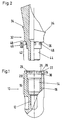
- the single tooth implant has a base body in the embodiment shown there 10 known type, as he is for example in DE-PS 40 28 855 is described.
- the base body 10 the one shown in Fig. 1 below cervical end is closed one towards its coronal end lying at the top in FIG. 1 open blind hole. Near the cervical end of the There is an internal thread 12 with a blind bore small diameter into which a in Fig. 1st implant post not shown on the is discussed below, can be screwed. On the internal thread 12 of the base body 10 closes in coronal Direction of an annular recess 14 with opposite Internal thread 12 increased diameter.
- the ring recess 14 points in one to the internal thread 12 coronally adjacent centering area 16 an internal thread 18 on. At the centering area 16 of the ring recess 14 closes a guide region 20 in the coronal direction in which the one opposite the centering area 16 enlarged ring recess 14 has a smooth, hollow cylindrical inner wall. Of the Guide area 20 to a coronal end edge 22 of the Base body 10 extends a form-locking area 24 the ring recess 14 in which a number of axial Form-fit grooves 26 in the inner wall of the ring recess 14 are incorporated.
- a spacer sleeve 32 shown in FIG. 2 serves in the in the unpublished German patent application P 195 09 762.9-32 explained way as a mounting head for a not shown fixed dentures and is with a circumferential attachment shoulder 34 for the dentures Mistake.
- the spacer sleeve 32 in the cervical direction a form-locking section 38, a Guide section 40 and a centering section 42 of a Centering collar 44.
- the form-fitting area 38 there are one Number of axially extending positive locking lugs 46 provided, those in their form and arrangement, albeit not necessarily in their number, the positive locking grooves 26 of the base body 10 correspond.
- the positive locking area 38 the spacer sleeve 32 has between the shoulder 36 and the Form-fitting lugs 46 have an annular undercut 48 on which the chip deposit-avoiding manufacture of the Form-fitting lugs 46 relieved.
- the centering section engages in the base body 10 42 of the centering collar 44 in the centering area 16 of the ring recess 14, so that the smooth cylindrical surface of the centering area 42 on the inner Limitation of the internal thread 18 of the centering area 16 of the base body 10 comes to rest.
- the leadership section 40 of the spacer 32 sits with a snug fit in the Guide area 20 of the base body 10.
- the positive locking lugs 46 engage in the form-fitting grooves 26, while the Shoulder 36 comes to rest on the front edge 22. In order to the spacer sleeve 32 is secured against rotation with the base body 10 connected.
- the spacer sleeve 32 By means of the penetrating the spacer sleeve 32 Implant post that fits into the internal thread 12 the base body 10 is screwed in, the spacer sleeve 32 firmly connect to the base body 10.
- the internal thread 18 of the Base body 10 for screwing in a different structure Spacer sleeve, for example a two-part as is known from DE-PS 40 28 855 used become.
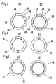
- the base body 10 has in its Positive locking area in 60 ° division six axial positive locking grooves 26 on that in the embodiment shown the cross-sectional shape of rectangles with essentially tangential, albeit curved, longitudinal edge to have.
- the base body 10 in turn has, as in FIG. 4 a) shows 12 positive locking grooves 26 in 30 ° division, while, 4b), the spacer sleeve 32 only is provided with four positive locking lugs 46.
- the positive locking grooves 26 and the positive locking lugs 46 have in this Fall in to the longitudinal axis of the base body or the spacer sleeve vertical plane triangular cross section. Noteworthy is that the spacer sleeve 32 here only four positive locking lugs 46 with 90 ° division.
- the base body has 10 in 30 ° division twelve positive locking grooves 26 with in a plane perpendicular to the longitudinal axis of the base body 10 circular segment-like cross-section.
- the spacer sleeve 32 in different rotational positions in the base body Insert 10, which gives the attending physician a number of design options is available.
Description
- Fig. 1
- ein Ausführungsbeispiel des Grundkörpers des enossalen Einzelzahnimplantates nach der Erfindung im axialen Längsschnitt;
- Fig. 2:
- eine Distanzhülse nebst Zahnersatz des Einzelzahnimplantates von Fig. 1 in Fig. 1 entsprechender Darstellung;
- Fig. 3:
- den Grundkörper (a)) und die Distanzhülse (b)) des Einzelzahnimplantates von Fig. 1 und Fig. 2 in der Ansicht von, bezogen auf Fig. 1, oben bzw., bezogen auf Fig. 2, von unten;
- Fig. 4
- in Fig. 3 entsprechender Darstellung den Grundkörper (a)) und die Distanzhülse (b)) eines anderen Ausführungsbeispieles der Erfindung; und
- Fig. 5
- in Fig. 3 und Fig. 4 entsprechender Darstellung den Grundkörper (a)) und die Distanzhülse (b)) eines weiteren Ausführungsbeispieles der Erfindung.
Claims (18)
- Enossales Einzelzahnimplantat für einen festsitzenden Zahnersatz, mit einem im wesentlichen zylindrischen, in eine in einen Kieferknochen eingebrachte Bohrung einsetzbaren Grundkörper (10), der eine zu seinem koronalen Ende offene Blindbohrung aufweist, einer an den koronalen Stirnrand des Grundkörpers verdrehgesichert ansetzbaren Distanzhülse (32), die einen zervikalen Zentrierbund (44) aufweist, der in eine am koronalen Ende des Grundkörpers vorgesehene hohlzylindrische Ringausnehmung (14) einsetzbar ist, eine in koronaler Richtung an den Zentrierbund anschließende, auf den koronalen Stirnrand des Grundkörpers aufsetzbare Schulter (36) aufweist und mit einer zu ihrem koronalen Ende offenen Bohrung zur Aufnahme des Implantatpfostens versehen ist, wobei eine Verbindungseinrichtung zum verdrehgesicherten Verbinden der Distanzhülse mit dem Grundkörper dadurch gebildet ist, daß die hohlzylindrische Ringausnehmung (14) des Grundkörpers mindestens ein in Umfangsrichtung wirksames Grundkörper-Formschlußelement (26) und der Zentrierbund der Distanzhülse mindestens ein zu dem/den Grundkörper-Formschlußelement(en) komplementäres Distanzhülsen-Formschlußelement (46) aufweist, einem in die Blindbohrung des Grundkörpers direkt oder indirekt einsetzbaren und die Distanzhülse zumindest teilweise durchsetzenden Implantatpfosten und einem Befestigungskopf für den Zahnersatz, dadurch gekennzeichnet, daß das/die Grundkörper-Formschlußelement(e) (26) an der Innenwandung der Ringausnehmung (14) in einem Formschlußbereich (24) derselben unmittelbar im Anschluß an den Stirnrand (22) des Grundkörpers (10) vorgesehen ist/sind; daß (eine) der Längsmittelachse der Ringausnehmung (14) nächstliegende(n) Führungsfläche(n) des/der Grundkörper-Formschlußelemente(s) (26) auf einer Zylinderfläche liegt/liegen, deren Durchmesser demjenigen eines sich zervikal an den Formschlußbereich (24) anschließenden Führungsbereiches (20) der Ringausnehmung (14) mit im wesentlichen glatter Umfangswandung entspricht; daß an den Führungsbereich (20) der Ringausnehmung (14) zervikal ein Zentrierbereich (16) der Ringausnehmung (14) mit gegenüber dem Führungsbereich (20) verringertem Durchmesser anschließt; daß das/die Distanzhülsen-Formschlußelement(e) zervikal im Anschluß an die Schulter (36) der Distanzhülse (32) an der zylindrischen Außenwandung des Zentrierbundes (44) in einem Formschlußabschnitt (38) desselben vorgesehen ist/sind; daß die radial am nächsten zur Längsmittelachse des Zentrierbundes (44) liegende(n) Umfangsfläche(n) des Formschlußabschnittes (38) auf der/denen das wenigstens eine Distanzhülsen-Formschlußelement (46) angeordnet ist, auf einer Zylinderfläche liegt liegen, deren Durchmesser im wesentlichen dem Innendurchmesser des Führungsbereiches (20) des Grundkörpers (10) entspricht; daß an den Formschlußabschnitt (38) zervikal ein zylindrischer Führungsabschnitt (40) anschließt, dessen Außendurchmesser im wesentlichen dem Innendurchmesser des Führungsbereiches (20) des Grundkörpers (10) entspricht; und daß an den Führungsabschnitt (40) zervikal ein zylinderförmiger Zentrierabschnitt (42) anschließt, dessen Außendurchmesser im wesentlichen mit dem Innendurchmesser des Zentrierbereiches (16) des Grundkörpers (10) übereinstimmt.
- Einzelzahnimplantat nach Anspruch 1, dadurch gekennzeichnet, daß der Zentrierbereich (16) des Grundkörpers (10) mit einem Innengewinde (18) versehen ist.
- Einzelzahnimplantat nach Anspruch 1 oder 2, dadurch gekennzeichnet, daß zervikal an den Zentrierbereich (16) des Grundkörpers (10) ein weiteres Innengewinde (12) anschließt.
- Einzelzahnimplantat nach Anspruch 3, dadurch gekennzeichnet, daß der Implantatpfosten die Distanzhülse (32) vollständig durchsetzt und in das weitere Innengewinde (12) nahe dem zervikalen Ende des Grundkörpers (10) einschraubbar ist.
- Einzelzahnimplantat nach einem der vorangehenden Ansprüche, dadurch gekennzeichnet, daß das/mindestens eines der Grundkörper-Formschlußelement(e) (26) die Form einer sich parallel zur Längsachse des Grundkörpers (10) erstreckenden, koronal offenen Formschlußnut hat.
- Einzelzahnimplantat nach Anspruch 5, dadurch gekennzeichnet, daß die Formschlußnut(en) (26) in einer radialen Ebene im wesentlichen kreissegmentförmigen Querschnitt hat/haben.
- Einzelzahnimplantat nach Anspruch 5, dadurch gekennzeichnet, daß die Formschlußnut(en) (26) in einer radialen Ebene im wesentlichen dreieckigen Querschnitt hat/haben.
- Einzelzahnimplantat nach Anspruch 5, dadurch gekennzeichnet, daß die Formschlußnut(en) (26) in einer radialen Ebene annähernd rechteckig-gebogenen Querschnitt hat/ haben.
- Einzelzahnimplantat nach einem der Ansprüche 5 bis 8, dadurch gekennzeichnet, daß die Formschlußnut(en) (26) zervikal offen ist/sind.
- Einzelzahnimplantat nach einem der Ansprüche 5 bis 9, dadurch gekennzeichnet, daß die Formschlußnut(en) (26) sich von ihrem koronalen zu ihrem zervikalen Ende verringernden Querschnitt aufweist/aufweisen.
- Einzelzahnimplantat nach Anspruch 10, dadurch gekennzeichnet, daß der Querschnitt der Formschlußnut(en) (26) sich von ihrem koronalen zu ihrem zervikalen Ende radial verringert.
- Einzelzahnimplantat nach einem der vorangehenden Ansprüche mit mehreren Grundkörper-Formschlußelementen, dadurch gekennzeichnet, daß die Grundkörper-Formschlußelemente (26) bezüglich des Umfangs des Grundkörpers (10) eine 30°-Teilung aufweisen.
- Einzelzahnimplantat nach einem der Ansprüche 1 bis 11 mit mehreren Grundkörper-Formschlußelementen, dadurch gekennzeichnet, daß die Grundkörper-Formschlußelemente (26) bezüglich des Umfangs des Grundkörpers (10) eine 60°-Teilung aufweisen.
- Einzelzahnimplantat nach einem der vorangehenden Ansprüche mit mehreren Grundkörper-Formschlußelementen, dadurch gekennzeichnet, daß die Anzahl der Distanzhülsen-Formschlußelemente (46) kleiner ist als diejenige der Grundkörper-Formschlußelemente (26).
- Einzelzahnimplantat nach einem der vorangehenden Ansprüche, dadurch gekennzeichnet, daß der Formschlußbereich (24) des Grundkörpers (10) zwischen dem/den Grundkörper-Formschlußelement(en) (26) und dem Führungsbereich (20) eine ringförmige Hinterschneidung (30) aufweist.
- Einzelzahnimplantat nach einem der vorangehenden Ansprüche, dadurch gekennzeichnet, daß die Innenwandung der Ringausnehmung (14) des Grundkörpers (10) eine sich zervikal vom koronalen Stirnrand (22) des Grundkörpers (10) bis in den Bereich des/der Grundkörper-Formschlußelemente(s) (26) konisch verjüngende Abschrägung (28) aufweist.
- Einzelzahnimplantat nach einem der vorangehenden Ansprüche, dadurch gekennzeichnet, daß der Formschlußabschnitt (38) des Zentrierbundes (44) zwischen der Schulter (36) und dem/den Distanzhülsen-Formschlußelement(en) (46) eine ringförmige Hinterschneidung (48) aufweist.
- Einzelzahnimplantat nach einem der vorangehenden Ansprüche, dadurch gekennzeichnet, daß die axiale Distanz zwischen dem Stirnrand (22) des Grundkörpers (10) und dem zervikalen Ende des Zentrierbereiches (16) des Grundkörpers (10) größer ist als der Innendurchmesser der Ringausnehmung (14) im Bereich des Formschlußbereiches (24).
Applications Claiming Priority (3)
| Application Number | Priority Date | Filing Date | Title |
|---|---|---|---|
| DE19534979A DE19534979C1 (de) | 1995-09-20 | 1995-09-20 | Enossales Einzelzahnimplantat mit Verdrehsicherung |
| DE19534979 | 1995-09-20 | ||
| PCT/DE1996/001455 WO1997010769A1 (de) | 1995-09-20 | 1996-07-31 | Enossales einzelzahnimplantat mit verdrehsicherung |
Publications (2)
| Publication Number | Publication Date |
|---|---|
| EP0851744A1 EP0851744A1 (de) | 1998-07-08 |
| EP0851744B1 true EP0851744B1 (de) | 1999-11-17 |
Family
ID=7772708
Family Applications (1)
| Application Number | Title | Priority Date | Filing Date |
|---|---|---|---|
| EP96931739A Expired - Lifetime EP0851744B1 (de) | 1995-09-20 | 1996-07-31 | Enossales einzelzahnimplantat mit verdrehsicherung |
Country Status (14)
| Country | Link |
|---|---|
| US (1) | US5823776A (de) |
| EP (1) | EP0851744B1 (de) |
| JP (1) | JP4065562B2 (de) |
| KR (2) | KR100435297B1 (de) |
| CN (1) | CN1104872C (de) |
| AT (1) | ATE186631T1 (de) |
| AU (1) | AU7082896A (de) |
| BR (1) | BR9610559A (de) |
| CA (1) | CA2232564C (de) |
| DE (2) | DE19534979C1 (de) |
| ES (1) | ES2140133T3 (de) |
| GR (1) | GR3032466T3 (de) |
| RU (1) | RU2155014C2 (de) |
| WO (1) | WO1997010769A1 (de) |
Cited By (1)
| Publication number | Priority date | Publication date | Assignee | Title |
|---|---|---|---|---|
| US9549793B2 (en) | 2002-11-13 | 2017-01-24 | Biomet 3I, Llc | Dental implant system |
Families Citing this family (87)
| Publication number | Priority date | Publication date | Assignee | Title |
|---|---|---|---|---|
| DE19633570C1 (de) * | 1996-08-21 | 1998-01-02 | Imz Fertigung Vertrieb | Enossales Einzelzahnimplantat mit Verdrehsicherung und Stanzwerkzeug sowie Positionierhilfe zur Fertigstellung eines solchen Einzelzahnimplantats |
| DE19718175A1 (de) * | 1997-04-29 | 1998-11-05 | Imz Fertigung Vertrieb | Konusförmiges Implantat |
| DE19718176C2 (de) * | 1997-04-29 | 2003-12-24 | Imz Fertigung Vertrieb | Konusförmiges Implantat |
| EP0984737B1 (de) * | 1997-05-24 | 2004-09-22 | Straumann Holding AG | Support zum halten und/oder bilden eines zahnersatzes |
| JP3481257B2 (ja) * | 1997-05-24 | 2003-12-22 | フランツ・ズツテル | 歯科用インプラントおよび歯科用インプラントをともなう装置 |
| AU9619898A (en) | 1997-08-13 | 1999-03-08 | Imz Fertigungs- Und Vertriebsgesellschaft Fur Dentale Technologie Mbh | Implant insert with a centering section to promote gingival growth |
| WO1999008618A1 (de) | 1997-08-13 | 1999-02-25 | Imz Fertigungs- Und Vertriebsgesellschaft Für Dentale Technologie Mbh | Implantateinsatz zum fördern des wachstums der gingiva |
| DE19815719C1 (de) * | 1998-04-08 | 2000-01-20 | Imz Fertigung Vertrieb | Enossales Einzelzahnimplantat mit Dichtring |
| CA2328183C (en) * | 1998-04-08 | 2007-10-30 | Imz Fertigungs- Und Vertriebsgesellschaft Fur Dentale Technologie Mbh | Intraosseous single-tooth implant |
| DE19828461B4 (de) * | 1998-04-08 | 2005-09-22 | IMZ - Fertigungs- und Vertriebsgesellschaft für dentale Technologie mbH | Enossales Einzelzahnimplantat mit Dichtring |
| US6102702A (en) * | 1998-12-28 | 2000-08-15 | Aubrey Clinton Folsom, Jr. | Quick tightening abutment lock |
| IT1307923B1 (it) * | 1999-01-25 | 2001-11-29 | Hofmann S A S Di Roberto Hofma | Dispositivo di impianto dentale endosseo. |
| IT1311004B1 (it) * | 1999-03-16 | 2002-02-27 | Antonio Gallicchio | Impianto per denti artificiali. |
| US8043089B2 (en) * | 1999-04-23 | 2011-10-25 | 3M Innovative Properties Company | One piece dental implant and use thereof in prostodontic and orthodontic applications |
| US8137103B1 (en) * | 1999-05-13 | 2012-03-20 | University Of Connecticut | Implant system |
| US6733291B1 (en) * | 1999-09-27 | 2004-05-11 | Nobel Biocare Usa, Inc. | Implant with internal multi-lobed interlock |
| DE19958338C2 (de) | 1999-12-03 | 2002-11-07 | Imz Fertigung Vertrieb | Enossales Einzelzahnimplantat |
| DE19958339C2 (de) * | 1999-12-03 | 2002-10-31 | Imz Fertigung Vertrieb | Enossales Einzelzahnimplantat mit Zentrierabschnitt |
| DE10052389A1 (de) * | 2000-10-20 | 2002-05-02 | Oraltronics Dental Implant Tec | Metallischer Prothesen-Halter und Verfahren zu seiner Herstellung |
| US20070037123A1 (en) * | 2000-10-26 | 2007-02-15 | Mansueto Robert F | High-strength dental-implant w/curvilinear-indexing and tool-free delivery-system |
| SE522958C2 (sv) | 2000-12-29 | 2004-03-16 | Nobel Biocare Ab | Förfarande, arrangemang (anordning) och program vid eller för protetisk installation |
| GB0108551D0 (en) | 2001-04-05 | 2001-05-23 | Osseobiotek Ltd | Implant |
| SE523395C2 (sv) | 2001-12-21 | 2004-04-13 | Nobel Biocare Ab | Implantat och förfarande och system för tillhandahållande av sådant implantat |
| SE520756C2 (sv) * | 2001-12-21 | 2003-08-19 | Nobel Biocare Ab | Förfarande för att åstadkomma ytstruktur på implantat samt sådant implantat |
| SE520765C2 (sv) * | 2001-12-28 | 2003-08-19 | Nobel Biocare Ab | Anordning och arrangemang för att medelst mall ta upp hål till implantat i ben, företrädesvis käkben |
| SE526666C2 (sv) * | 2002-12-30 | 2005-10-25 | Nobel Biocare Ab | Anordning och arrangemang för fixturinstallation |
| SE526667C2 (sv) * | 2002-12-30 | 2005-10-25 | Nobel Biocare Ab | Anordning vid implantat och förfarande för framställning av implantatet |
| SE526665C2 (sv) * | 2002-12-30 | 2005-10-25 | Nobel Biocare Ab | Anordning vid dentalt fastskruvningsarrangemang |
| CA2518312A1 (en) * | 2003-03-13 | 2004-09-23 | Young Ku Heo | Method for treating a screw-cement retained prosthesis, abutment and implant for a screw-cement retained prosthesis |
| IL156033A0 (en) | 2003-05-21 | 2004-03-28 | Ophir Fromovich Ophir Fromovic | Dental implant |
| WO2005016168A2 (en) * | 2003-08-11 | 2005-02-24 | Imtec Corporation | Dental implant system |
| US7014464B2 (en) * | 2003-12-19 | 2006-03-21 | Niznick Gerald A | Multi-part abutment and transfer cap for use with an endosseous dental implant with non-circular, beveled implant/abutment interface |
| AR043256A1 (es) * | 2004-02-20 | 2005-07-20 | Odontit S A | Una disposicion de implante dental integrado al hueso para sostener una protesis dental |
| EP1579818B1 (de) * | 2004-03-25 | 2007-08-01 | Straumann Holding AG | Dentalimplantat mit Positionierungsmittel |
| US7249949B2 (en) * | 2004-06-29 | 2007-07-31 | Lifecore Biomedical, Inc. | Internal connection dental implant |
| SE527503C2 (sv) * | 2004-08-05 | 2006-03-21 | Nobel Biocare Ab | Anordning och förfarande för att underlätta applicering till rätt läge av tand- eller tandrestmall |
| DE202005000208U1 (de) * | 2005-01-07 | 2005-07-07 | Lippe, Rainer | In einem menschlichen Kiefer einschraubbares Dentalimplantat zur Aufnahme und Fixierung eines Zahnersatzes |
| ES2307352B1 (es) | 2005-04-12 | 2009-09-18 | Bti, I+D, S.L. | Implante dental y piezas destinadas a ser conectadas a un implante dental, y la conexion interna entre el implante dental y cada pieza. |
| EP2119414B1 (de) | 2005-06-03 | 2013-04-24 | Straumann Holding AG | Kupplung für mehrteiliges Zahnimplantatsystem |
| US7351060B2 (en) * | 2005-06-14 | 2008-04-01 | Ho Chih-Chung | Abutment for dental implant |
| US8430668B2 (en) * | 2005-06-17 | 2013-04-30 | Zimmer Dental, Inc. | Dental restorative system and components |
| US8506296B2 (en) * | 2005-06-17 | 2013-08-13 | Zimmer Dental, Inc. | Dental restorative system and components |
| US8007279B2 (en) * | 2005-06-17 | 2011-08-30 | Zimmer Dental, Inc. | Dental restorative system and components |
| US20070037121A1 (en) | 2005-08-10 | 2007-02-15 | Carter Robert D | Carry and drive device and method for dental implant and/or components thereof |
| DE102006005667B4 (de) * | 2006-01-31 | 2009-05-28 | Wieland Dental Implants Gmbh | Zahnimplantat, Verschlussschraube und Abutment für ein solches Zahnimplantat |
| US20090035721A1 (en) * | 2006-02-16 | 2009-02-05 | Francisco Javier Garcia Saban | Dental implant and dental impression-taking device assembly |
| BRPI0711288B8 (pt) | 2006-05-04 | 2021-06-22 | Nobel Biocare Services Ag | dispositivo para fixar um implante dentário ao tecido ósseo de um paciente. |
| EP1894541B1 (de) * | 2006-08-29 | 2013-03-20 | Straumann Holding AG | Aufbaupfosten für ein Dentalimplantat |
| US10206757B2 (en) | 2007-01-10 | 2019-02-19 | Nobel Biocare Services Ag | Method and system for dental planning and production |
| JP5789860B2 (ja) * | 2007-03-14 | 2015-10-07 | デンツプライ インターナショナル インコーポレーテッド | フィレットを有する人工橋脚歯 |
| US8038442B2 (en) | 2007-04-23 | 2011-10-18 | Nobel Biocare Services Ag | Dental implant and dental component connection |
| US7806693B2 (en) | 2007-04-23 | 2010-10-05 | Nobel Biocare Services Ag | Dental implant |
| JP2010533516A (ja) * | 2007-07-16 | 2010-10-28 | デンタルポイント アーゲー | 歯牙インプラント |
| US20090111072A1 (en) * | 2007-10-30 | 2009-04-30 | Alan Lombardo | Dental implant and abutment mating system |
| US9055988B2 (en) * | 2007-11-09 | 2015-06-16 | Southern Implants (Pty) Ltd. | Dental implant adaptor |
| JP5571876B2 (ja) * | 2008-04-09 | 2014-08-13 | 康 中島 | 歯科用インプラント |
| US20100151420A1 (en) * | 2008-12-11 | 2010-06-17 | Ranck Roger S | Fixtures for dental implants |
| US20100209877A1 (en) | 2009-02-13 | 2010-08-19 | Stephen Hogan | Components for use with implants and related methods |
| US20100151423A1 (en) * | 2008-12-11 | 2010-06-17 | Ranck Roger S | Temporary restorations and related methods |
| US8075313B2 (en) | 2009-01-19 | 2011-12-13 | Aeton Medical Llc | Transfer copings and related methods for taking implant impressions |
| DK2215989T3 (da) * | 2009-02-05 | 2019-09-23 | Ivoclar Vivadent Ag | Konstruktionsdel til et tandimplantat |
| EP2254068B1 (de) | 2009-05-18 | 2020-08-19 | Nobel Biocare Services AG | Verfahren und System, die einen verbesserten Datenabgleich zur virtuellen Planung bereitstellen |
| JP5259557B2 (ja) * | 2009-11-20 | 2013-08-07 | 興達生技有限公司 | 歯科インプラント |
| EP2332489A1 (de) * | 2009-12-14 | 2011-06-15 | AIDI Biomedical International | Zahnimplantat |
| EP2347729A1 (de) * | 2010-01-21 | 2011-07-27 | Camlog Biotechnologies AG | Zahnimplantat, Abutment für ein Zahnimplantat und Kombination davon sowie ein Implantations-Set |
| HUP1000219A2 (en) | 2010-04-20 | 2012-03-28 | Zoltan Szakacs | Dental implant, dental abutment and dental kit |
| US9259297B2 (en) * | 2010-09-24 | 2016-02-16 | Zimmer Dental, Inc. | Dental implant and abutment system |
| CH704382A1 (de) * | 2011-01-25 | 2012-07-31 | Dentalpoint Ag | Zahnersatz-System. |
| WO2012115969A2 (en) | 2011-02-21 | 2012-08-30 | Aeton Medical Llc | Abutment and abutment systems for use with implants |
| FR2972625B1 (fr) † | 2011-03-15 | 2014-02-28 | Biotech Internat | Implant dentaire |
| US9925024B2 (en) | 2011-06-28 | 2018-03-27 | Biomet 3I, Llc | Dental implant and abutment tools |
| WO2013008962A1 (ko) * | 2011-07-11 | 2013-01-17 | (주)시원 | 각진 마찰결합식 치과용 임플란트 |
| EP2570097A1 (de) * | 2011-09-14 | 2013-03-20 | Dentsply IH AB | Zahnkomponente, Zahnimplantatanker und Zahnimplantat |
| EP2570095A1 (de) * | 2011-09-14 | 2013-03-20 | Dentsply IH AB | Zahnkomponente und Zahnimplantat |
| DE202012103424U1 (de) | 2011-12-09 | 2013-03-11 | Epiphanostics GmbH | Enossales Einzelzahnimplantat |
| USD731655S1 (en) | 2013-03-15 | 2015-06-09 | Benedict Lui | Dental implant abutment |
| EP2839806A1 (de) * | 2013-08-23 | 2015-02-25 | Rolf G. Winnen | Vorrichtung zur kontrollierten Beseitungung von osseointegrierten Implantaten und verbesserte abbaubare Implantate |
| USD732169S1 (en) | 2013-09-16 | 2015-06-16 | Benedict Lui | Dental implant abutment |
| JP6566955B2 (ja) | 2013-12-17 | 2019-08-28 | エピファノスティクス ゲーエムベーハー | エノスザールな単一義歯移植 |
| ES2556149A1 (es) * | 2014-07-10 | 2016-01-13 | Montserrat TERRATS TRIQUELL | Aditamento dental, conjunto de aditamento y tornillo, y sistema de implante dental |
| CA2966380A1 (en) | 2014-11-06 | 2016-05-12 | Epiphanostics GmbH | Enossal single tooth implant |
| BR102014031426B1 (pt) | 2014-12-15 | 2018-07-24 | Jjgc Ind E Comercio De Materiais Dentarios S/A | implante |
| CL2015001657S1 (es) | 2014-12-15 | 2016-09-02 | Jjgc Indústria E Comércio De Materiais Dentários S A | Configuracion aplicada a implante oseo. |
| EP3095409A1 (de) | 2015-05-21 | 2016-11-23 | Epiphanostics GmbH | Insertionsset für ein enossales einzelzahnimplantat |
| BR102016010184B1 (pt) | 2016-05-05 | 2020-10-27 | Jjgc Indústria E Comércio De Materiais Dentários S.A. | conjunto protético e processo para produção do mesmo |
| CN108542521A (zh) * | 2018-05-03 | 2018-09-18 | 武汉贝恩康医疗科技有限公司 | 一种口腔种植体装置 |
| CN111904633B (zh) * | 2020-07-27 | 2022-02-15 | 赤峰学院附属医院 | 一种用于种植牙牙冠与基台体外粘接的辅助装置 |
Family Cites Families (17)
| Publication number | Priority date | Publication date | Assignee | Title |
|---|---|---|---|---|
| CH413224A (fr) * | 1964-12-02 | 1966-05-15 | Brunner Fernand | Implant dentaire |
| GB2199626B (en) * | 1987-01-08 | 1991-09-04 | Core Vent Corp | Screw-type dental implant anchor |
| US5078607A (en) * | 1987-01-08 | 1992-01-07 | Core-Vent Corporation | Dental implant including plural anchoring means |
| DE3917690A1 (de) * | 1989-05-31 | 1990-12-13 | Kirsch Axel | Enossales einzelzahnimplantat sowie konterwerkzeug zur verwendung bei einem derartigen implantat |
| US5000686A (en) * | 1990-01-02 | 1991-03-19 | Implant Innovations, Inc. | Dental implant fixture |
| EP0438048B1 (de) * | 1990-01-15 | 1994-05-18 | Friatec Aktiengesellschaft Keramik- und Kunststoffwerke | Dentalimplantat |
| DE4022753A1 (de) * | 1990-07-18 | 1992-01-23 | Wolfgang Tartsch | Zahnimplantat mit kopfpositionierung und verfahren zur herstellung einer zahnprothese |
| FR2664808A1 (fr) * | 1990-07-23 | 1992-01-24 | Gersberg Eduardo | Systeme d'implants dentaires. |
| DE4127436A1 (de) * | 1990-08-21 | 1992-03-05 | Gerold Klaus | Vorrichtung zur befestigung einer zahnprothese an implantaten oder wurzelkappen |
| DE4127839A1 (de) * | 1990-09-01 | 1992-03-19 | Gerold Klaus | Vorrichtung zum befestigen von zahnersatz an einem implantat |
| JP3001300B2 (ja) * | 1990-09-08 | 2000-01-24 | イー・エム・ツエツト・フエルテイグングス−ウント・フエアトリープスゲゼルシヤフト・フエーア・デンタール・テヒノロギー・エムベーハー | 骨に取付ける単一歯植込み部材 |
| WO1994020043A1 (en) * | 1991-12-30 | 1994-09-15 | Wellesley Research Associates, Inc. | Dental implant system and apparatus |
| FR2695823A1 (fr) * | 1992-09-24 | 1994-03-25 | Spid Sa | Implant dentaire évolué et évolutif. |
| DE4238383A1 (de) * | 1992-11-13 | 1994-07-14 | Stephan Dipl Ing Fath | Selbstschneidendes Zylinderschraubimplantat mit mehrgängigem Gewinde |
| US5449291A (en) * | 1993-12-21 | 1995-09-12 | Calcitek, Inc. | Dental implant assembly having tactile feedback |
| US5620323A (en) * | 1994-08-22 | 1997-04-15 | Bressman; Robert A. | Dental restoration structure |
| US5577912A (en) * | 1994-09-19 | 1996-11-26 | Prins; Steven P. | Adjustable implant fixture |
-
1995
- 1995-09-20 DE DE19534979A patent/DE19534979C1/de not_active Expired - Lifetime
-
1996
- 1996-07-31 CN CN96197092A patent/CN1104872C/zh not_active Expired - Fee Related
- 1996-07-31 KR KR10-1998-0702004A patent/KR100435297B1/ko active IP Right Grant
- 1996-07-31 DE DE59603683T patent/DE59603683D1/de not_active Expired - Lifetime
- 1996-07-31 CA CA002232564A patent/CA2232564C/en not_active Expired - Fee Related
- 1996-07-31 EP EP96931739A patent/EP0851744B1/de not_active Expired - Lifetime
- 1996-07-31 BR BR9610559A patent/BR9610559A/pt not_active IP Right Cessation
- 1996-07-31 AT AT96931739T patent/ATE186631T1/de active
- 1996-07-31 ES ES96931739T patent/ES2140133T3/es not_active Expired - Lifetime
- 1996-07-31 RU RU98107247/14A patent/RU2155014C2/ru not_active IP Right Cessation
- 1996-07-31 AU AU70828/96A patent/AU7082896A/en not_active Abandoned
- 1996-07-31 WO PCT/DE1996/001455 patent/WO1997010769A1/de active IP Right Grant
- 1996-07-31 JP JP51229297A patent/JP4065562B2/ja not_active Expired - Fee Related
- 1996-08-22 US US08/701,688 patent/US5823776A/en not_active Expired - Lifetime
- 1996-09-10 KR KR1019970709271A patent/KR100269977B1/ko not_active IP Right Cessation
-
2000
- 2000-01-25 GR GR20000400160T patent/GR3032466T3/el unknown
Cited By (3)
| Publication number | Priority date | Publication date | Assignee | Title |
|---|---|---|---|---|
| US9549793B2 (en) | 2002-11-13 | 2017-01-24 | Biomet 3I, Llc | Dental implant system |
| US9883927B2 (en) | 2002-11-13 | 2018-02-06 | Biomet 3I, Llc | Dental implant system |
| US9931182B2 (en) | 2002-11-13 | 2018-04-03 | Biomet 3I, Llc | Dental implant system |
Also Published As
| Publication number | Publication date |
|---|---|
| CA2232564A1 (en) | 1997-03-27 |
| CN1104872C (zh) | 2003-04-09 |
| US5823776A (en) | 1998-10-20 |
| KR100269977B1 (ko) | 2000-11-01 |
| JP4065562B2 (ja) | 2008-03-26 |
| DE59603683D1 (de) | 1999-12-23 |
| AU7082896A (en) | 1997-04-09 |
| KR19990022802A (ko) | 1999-03-25 |
| DE19534979C1 (de) | 1997-01-09 |
| EP0851744A1 (de) | 1998-07-08 |
| KR100435297B1 (ko) | 2004-09-08 |
| JPH11512324A (ja) | 1999-10-26 |
| ES2140133T3 (es) | 2000-02-16 |
| CA2232564C (en) | 2001-04-24 |
| WO1997010769A1 (de) | 1997-03-27 |
| KR19990045760A (ko) | 1999-06-25 |
| BR9610559A (pt) | 1999-07-06 |
| ATE186631T1 (de) | 1999-12-15 |
| RU2155014C2 (ru) | 2000-08-27 |
| GR3032466T3 (en) | 2000-05-31 |
| CN1196670A (zh) | 1998-10-21 |
Similar Documents
| Publication | Publication Date | Title |
|---|---|---|
| EP0851744B1 (de) | Enossales einzelzahnimplantat mit verdrehsicherung | |
| EP1843717B1 (de) | Dentalimplantat | |
| EP3156000B1 (de) | Zahnimplantat, abutment für ein zahnimplantat und kombination davon sowie ein implantations-set | |
| EP1069868B1 (de) | Enossales einzelzahnimplantat | |
| EP2787920B1 (de) | Enossales einzelzahnimplantat | |
| EP2882370B1 (de) | Sekundärteil, set und verpackung für ein dentalimplantatsystem | |
| EP3082640B1 (de) | Enossales einzelzahnimplantat | |
| DE102016008669B4 (de) | Suprastrukturträger mit besonderer Implantatpfostengeometrie | |
| EP3496653B1 (de) | Dentalimplantat mit buchsenkörper und bausatz für selbiges | |
| EP2829250B1 (de) | Dentalimplantat, Abutment, Implantatsystem und Implantationsset | |
| WO2000000102A1 (de) | Übertragungselement | |
| DE102016008668A1 (de) | Suprastrukturträger mit besonderer Innen- und Außengeometrie | |
| EP2399540A2 (de) | Enossales Kieferimplantat zum Einsetzen in eine in einem Kieferknochen vorbereitete Kavität und Schablone zur Einbringung der Kavität in den Kieferknochen | |
| EP0984734B1 (de) | Konusförmiges implantat | |
| WO2021013376A1 (de) | Abdruckpfosten zum verbinden mit einem zahnimplantat | |
| DE102008033367A1 (de) | Dentalimplantat | |
| EP0984736B1 (de) | Konusförmiges implantat | |
| DE19828461B4 (de) | Enossales Einzelzahnimplantat mit Dichtring | |
| DE20022420U1 (de) | Konusförmiges Implantat mit Schneidkante | |
| EP0891748B1 (de) | Gingivaformer | |
| DE19829504A1 (de) | Enossales Einzelzahnimplantat mit verlängertem Zentrierbereich | |
| DE102015103288A1 (de) | Implantatsystem und Verfahren zur Einpflanzung eines Dentalimplantats | |
| DE4035172A1 (de) | Enossales kieferimplantat in gestalt eines schraubenimplantats zum befestigen von zahnersatz | |
| DE102009024582A1 (de) | Implantatschraube für ein Zahnimplantat |
Legal Events
| Date | Code | Title | Description |
|---|---|---|---|
| PUAI | Public reference made under article 153(3) epc to a published international application that has entered the european phase |
Free format text: ORIGINAL CODE: 0009012 |
|
| 17P | Request for examination filed |
Effective date: 19980223 |
|
| AK | Designated contracting states |
Kind code of ref document: A1 Designated state(s): AT BE CH DE DK ES FI FR GB GR IE IT LI NL PT SE |
|
| GRAG | Despatch of communication of intention to grant |
Free format text: ORIGINAL CODE: EPIDOS AGRA |
|
| 17Q | First examination report despatched |
Effective date: 19990205 |
|
| GRAG | Despatch of communication of intention to grant |
Free format text: ORIGINAL CODE: EPIDOS AGRA |
|
| GRAH | Despatch of communication of intention to grant a patent |
Free format text: ORIGINAL CODE: EPIDOS IGRA |
|
| GRAH | Despatch of communication of intention to grant a patent |
Free format text: ORIGINAL CODE: EPIDOS IGRA |
|
| GRAA | (expected) grant |
Free format text: ORIGINAL CODE: 0009210 |
|
| AK | Designated contracting states |
Kind code of ref document: B1 Designated state(s): AT BE CH DE DK ES FI FR GB GR IE IT LI NL PT SE |
|
| REF | Corresponds to: |
Ref document number: 186631 Country of ref document: AT Date of ref document: 19991215 Kind code of ref document: T |
|
| REG | Reference to a national code |
Ref country code: CH Ref legal event code: NV Representative=s name: BUECHEL & PARTNER AG PATENTBUERO Ref country code: CH Ref legal event code: EP |
|
| GBT | Gb: translation of ep patent filed (gb section 77(6)(a)/1977) |
Effective date: 19991117 |
|
| REF | Corresponds to: |
Ref document number: 59603683 Country of ref document: DE Date of ref document: 19991223 |
|
| REG | Reference to a national code |
Ref country code: IE Ref legal event code: FG4D Free format text: GERMAN |
|
| ET | Fr: translation filed | ||
| ITF | It: translation for a ep patent filed |
Owner name: FUMERO BREVETTI S.N.C. |
|
| REG | Reference to a national code |
Ref country code: ES Ref legal event code: FG2A Ref document number: 2140133 Country of ref document: ES Kind code of ref document: T3 |
|
| PG25 | Lapsed in a contracting state [announced via postgrant information from national office to epo] |
Ref country code: PT Free format text: LAPSE BECAUSE OF FAILURE TO SUBMIT A TRANSLATION OF THE DESCRIPTION OR TO PAY THE FEE WITHIN THE PRESCRIBED TIME-LIMIT Effective date: 20000217 Ref country code: DK Free format text: LAPSE BECAUSE OF FAILURE TO SUBMIT A TRANSLATION OF THE DESCRIPTION OR TO PAY THE FEE WITHIN THE PRESCRIBED TIME-LIMIT Effective date: 20000217 |
|
| PG25 | Lapsed in a contracting state [announced via postgrant information from national office to epo] |
Ref country code: IE Free format text: LAPSE BECAUSE OF NON-PAYMENT OF DUE FEES Effective date: 20000621 |
|
| REG | Reference to a national code |
Ref country code: IE Ref legal event code: FD4D |
|
| PLBE | No opposition filed within time limit |
Free format text: ORIGINAL CODE: 0009261 |
|
| STAA | Information on the status of an ep patent application or granted ep patent |
Free format text: STATUS: NO OPPOSITION FILED WITHIN TIME LIMIT |
|
| 26N | No opposition filed | ||
| REG | Reference to a national code |
Ref country code: GB Ref legal event code: IF02 |
|
| REG | Reference to a national code |
Ref country code: CH Ref legal event code: NV Representative=s name: HEPP, WENGER & RYFFEL AG |
|
| BECA | Be: change of holder's address |
Owner name: *CAMLOG BIOTECHNOLOGIES A.B.STEINENGRABEN 22, CH-4 Effective date: 20050531 |
|
| BECH | Be: change of holder |
Owner name: *CAMLOG BIOTECHNOLOGIES A.B. Effective date: 20050531 |
|
| REG | Reference to a national code |
Ref country code: CH Ref legal event code: PUE Owner name: CAMLOG BIOTECHNOLOGIES AG Free format text: IMZ-FERTIGUNGS- UND VERTRIEBSGESELLSCHAFT FUER DENTALE TECHNOLOGIE MBH#TALSTRASSE 23#70794 FILDERSTADT (DE) -TRANSFER TO- CAMLOG BIOTECHNOLOGIES AG#STEINENGRABEN 22#4051 BASEL (CH) |
|
| REG | Reference to a national code |
Ref country code: GB Ref legal event code: 732E |
|
| NLS | Nl: assignments of ep-patents |
Owner name: CAMLOG BIOTECHNOLOGIES AG |
|
| NLT1 | Nl: modifications of names registered in virtue of documents presented to the patent office pursuant to art. 16 a, paragraph 1 |
Owner name: ALTATEC GMBH |
|
| REG | Reference to a national code |
Ref country code: FR Ref legal event code: CD Ref country code: FR Ref legal event code: CA |
|
| REG | Reference to a national code |
Ref country code: FR Ref legal event code: TP |
|
| REG | Reference to a national code |
Ref country code: ES Ref legal event code: PC2A |
|
| BECA | Be: change of holder's address |
Owner name: *CAMLOG BIOTECHNOLOGIES A.B.STEINENGRABEN 22, CH-4 Effective date: 20050531 |
|
| BECH | Be: change of holder |
Owner name: *CAMLOG BIOTECHNOLOGIES A.B. Effective date: 20050531 |
|
| PGFP | Annual fee paid to national office [announced via postgrant information from national office to epo] |
Ref country code: ES Payment date: 20140627 Year of fee payment: 19 Ref country code: GR Payment date: 20140630 Year of fee payment: 19 |
|
| PGFP | Annual fee paid to national office [announced via postgrant information from national office to epo] |
Ref country code: NL Payment date: 20140710 Year of fee payment: 19 Ref country code: FI Payment date: 20140710 Year of fee payment: 19 |
|
| PGFP | Annual fee paid to national office [announced via postgrant information from national office to epo] |
Ref country code: SE Payment date: 20140711 Year of fee payment: 19 Ref country code: GB Payment date: 20140730 Year of fee payment: 19 Ref country code: AT Payment date: 20140626 Year of fee payment: 19 Ref country code: FR Payment date: 20140708 Year of fee payment: 19 |
|
| PGFP | Annual fee paid to national office [announced via postgrant information from national office to epo] |
Ref country code: IT Payment date: 20140717 Year of fee payment: 19 |
|
| PGFP | Annual fee paid to national office [announced via postgrant information from national office to epo] |
Ref country code: BE Payment date: 20140714 Year of fee payment: 19 |
|
| PGFP | Annual fee paid to national office [announced via postgrant information from national office to epo] |
Ref country code: DE Payment date: 20150729 Year of fee payment: 20 |
|
| PGFP | Annual fee paid to national office [announced via postgrant information from national office to epo] |
Ref country code: CH Payment date: 20151001 Year of fee payment: 20 |
|
| REG | Reference to a national code |
Ref country code: AT Ref legal event code: MM01 Ref document number: 186631 Country of ref document: AT Kind code of ref document: T Effective date: 20150731 |
|
| GBPC | Gb: european patent ceased through non-payment of renewal fee |
Effective date: 20150731 |
|
| REG | Reference to a national code |
Ref country code: SE Ref legal event code: EUG |
|
| REG | Reference to a national code |
Ref country code: NL Ref legal event code: MM Effective date: 20150801 |
|
| PG25 | Lapsed in a contracting state [announced via postgrant information from national office to epo] |
Ref country code: IT Free format text: LAPSE BECAUSE OF NON-PAYMENT OF DUE FEES Effective date: 20150731 Ref country code: GB Free format text: LAPSE BECAUSE OF NON-PAYMENT OF DUE FEES Effective date: 20150731 |
|
| REG | Reference to a national code |
Ref country code: FR Ref legal event code: ST Effective date: 20160331 |
|
| PG25 | Lapsed in a contracting state [announced via postgrant information from national office to epo] |
Ref country code: AT Free format text: LAPSE BECAUSE OF NON-PAYMENT OF DUE FEES Effective date: 20150731 Ref country code: SE Free format text: LAPSE BECAUSE OF NON-PAYMENT OF DUE FEES Effective date: 20150801 Ref country code: NL Free format text: LAPSE BECAUSE OF NON-PAYMENT OF DUE FEES Effective date: 20150801 Ref country code: FI Free format text: LAPSE BECAUSE OF NON-PAYMENT OF DUE FEES Effective date: 20150731 Ref country code: GR Free format text: LAPSE BECAUSE OF NON-PAYMENT OF DUE FEES Effective date: 20160202 Ref country code: FR Free format text: LAPSE BECAUSE OF NON-PAYMENT OF DUE FEES Effective date: 20150731 |
|
| REG | Reference to a national code |
Ref country code: GR Ref legal event code: ML Ref document number: 20000400160 Country of ref document: GR Effective date: 20160202 |
|
| REG | Reference to a national code |
Ref country code: DE Ref legal event code: R071 Ref document number: 59603683 Country of ref document: DE |
|
| REG | Reference to a national code |
Ref country code: CH Ref legal event code: PL |
|
| REG | Reference to a national code |
Ref country code: ES Ref legal event code: FD2A Effective date: 20160826 |
|
| PG25 | Lapsed in a contracting state [announced via postgrant information from national office to epo] |
Ref country code: ES Free format text: LAPSE BECAUSE OF NON-PAYMENT OF DUE FEES Effective date: 20150801 |
|
| PG25 | Lapsed in a contracting state [announced via postgrant information from national office to epo] |
Ref country code: BE Free format text: LAPSE BECAUSE OF NON-PAYMENT OF DUE FEES Effective date: 20150731 |