EP0851549B1 - Überspannungsableiter mit einem aus thermoplastischen Material hergestellten Gehäuse mit einer äusseren geprägten Oberfläche - Google Patents
Überspannungsableiter mit einem aus thermoplastischen Material hergestellten Gehäuse mit einer äusseren geprägten Oberfläche Download PDFInfo
- Publication number
- EP0851549B1 EP0851549B1 EP97403081A EP97403081A EP0851549B1 EP 0851549 B1 EP0851549 B1 EP 0851549B1 EP 97403081 A EP97403081 A EP 97403081A EP 97403081 A EP97403081 A EP 97403081A EP 0851549 B1 EP0851549 B1 EP 0851549B1
- Authority
- EP
- European Patent Office
- Prior art keywords
- envelope
- electrical components
- fittings
- thermoplastic material
- stack
- Prior art date
- Legal status (The legal status is an assumption and is not a legal conclusion. Google has not performed a legal analysis and makes no representation as to the accuracy of the status listed.)
- Expired - Lifetime
Links
Images
Classifications
-
- H—ELECTRICITY
- H01—ELECTRIC ELEMENTS
- H01T—SPARK GAPS; OVERVOLTAGE ARRESTERS USING SPARK GAPS; SPARKING PLUGS; CORONA DEVICES; GENERATING IONS TO BE INTRODUCED INTO NON-ENCLOSED GASES
- H01T1/00—Details of spark gaps
- H01T1/15—Details of spark gaps for protection against excessive pressure
-
- H—ELECTRICITY
- H01—ELECTRIC ELEMENTS
- H01C—RESISTORS
- H01C7/00—Non-adjustable resistors formed as one or more layers or coatings; Non-adjustable resistors made from powdered conducting material or powdered semi-conducting material with or without insulating material
- H01C7/10—Non-adjustable resistors formed as one or more layers or coatings; Non-adjustable resistors made from powdered conducting material or powdered semi-conducting material with or without insulating material voltage responsive, i.e. varistors
- H01C7/12—Overvoltage protection resistors; Arresters
- H01C7/126—Means for protecting against excessive pressure or for disconnecting in case of failure
Definitions
- the invention relates to a surge arrester or surge arrester comprising two metal connection frames, a stack of conductive electrical components extending along a longitudinal axis between the two fittings, an envelope surrounding the electrical components and reinforcements so as to maintain electrical contact between these components.
- Such a surge arrester or lightning arrester is intended to be connected to electrical equipment to derive the overcurrent pulses. Of such overcurrent pulses occur, for example, during strokes lightning. When this occurs, the arrester derives the overcurrent pulse at the earth, thereby protecting the electrical equipment and circuit from damage or destruction.
- U.S. Patent No. 3,018,406 describes a surge arrester having a casing in thermosetting material molded on components electric. To avoid inclusions of this material between the electrical components during molding, the electrical components are protected by two prefabricated half-shells.
- the envelope surrounding the conductive electrical components is constituted by a winding of resin-impregnated glass fibers, the assembly being housed in an insulating casing made of weatherproof elastomeric polymer.
- the overvoltage diverter according to the invention as defined by claim 1 remedies the drawbacks indicated above.
- An overpressure of the gases inside the envelope therefore causes the rupture of the envelope at its thinner areas and therefore of greater brittleness, that is to say at the level of the hollows of the embossed surface, which allows the venting of gases through the openings thus created without risk bursting lightning arrester.
- the dinghy according to the invention is of low cost over time reduced manufacturing.
- the envelope of such a dinghy can be produced by molding by injection or compression of the thermoplastic material on the electrical components and metal fittings. It is free of inclusion air or humidity between the electrical components and the enclosure or between the envelope and the casing made of elastomeric polymer material which surrounds the envelope.
- the use of thermoplastic material is particularly advantageous since this material has a very short cycle time.
- the molding is making on a cold column (the electrical components in the mold being brought to a temperature of around 80 ° c while the thermoplastic material in the mold being at a melting temperature of about 270 ° c), this material thermoplastic, whose melting point is generally very narrow, tends to freeze very quickly on contact with electrical components and does not get in not between these components. So there is no need to protect electrical components by a film used to avoid the inclusion of material between electrical components.
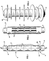
- Figure 1 very schematically shows an assembly comprising a stacking of varistor blocks between two armatures to constitute a insert.
- Figure 2 shows very schematically the assembly of Figure 1 fitted with a thermoplastic envelope, the outer surface of which an embossed structure.
- FIG. 3 shows very schematically the surge arrester according to the invention with its elastomeric polymer housing.
- the surge arrester or surge arrester according to the invention includes a set of electrically conductive components in the event of overvoltage, for example cylindrical blocks of varistor 1, aligned in row along a longitudinal axis 2 and in contact with each other by their appropriate end faces. On each end face of the stack of varistor blocks is placed a metal connection frame 3.
- Each frame 3 has an annular groove indicated by 4 which extends perpendicular to axis 2 and which has facets 4a, 4b, 4c giving in cross section to axis 2 a polygonal shape, for example hexagonal.
- an envelope 6 surrounds the varistor blocks 1 and the reinforcements 3.
- this envelope is made from a material thermoplastic and has an embossed outer surface with depressions 7 and bumps 8 and 9.
- thermoplastic material is molded on the outer surface of assembly 5 consisting of the stack of varistors 1 and the armatures metal 3.
- the casing 6 can be produced for example, by molding by injection of the thermoplastic material into an injection mold containing assembly 5 which avoids the risk of air or humidity inclusions between the varistor blocks and the envelope.
- Envelope 6 can also be prefabricated to be in the form of a tube made of material thermoplastic. Assembly 5 is introduced into the prefabricated envelope which is then compression molded, in a compression mold, onto the assembly 5 so as to obtain recesses 7 corresponding to zones thinner envelope.
- the envelope 6, at the level of these zones of thinner thickness is likely to rupture locally under significant gas pressure and side openings thus formed by rupture are used to vent the gas.
- the bumps on the outer surface of the casing 6 define longitudinal ribs 8 and radial 9 with respect to the axis 2. These ribs serve to constitute reinforcements to ensure the mechanical strength and the rigidity of the insert constituted by the assembly 5 and the envelope 6.
- assembly 5 is heated in an oven to bring its temperature to approximately 80 ° C so as to reduce, when the plastic material hardens, stresses due to differential expansion.
- the plastic material of the envelope fills the grooves 4 of reinforcements 3 so that the envelope engaged in these grooves ensures contact between the varistor blocks and prevents, due to the presence of facets, a rotational movement of the reinforcements 3 around the axis 2.
- This plastic material can advantageously be loaded with cut fiberglass or silica to increase its characteristics mechanical and self-extinguishing.
- a material thermoplastic with a very narrow melting point for example, a polyamide, a polyoxymethylene or even a polyphthalamide, to make the envelope.
- the envelope 6 of the insert is enclosed in a housing in elastomeric polymeric material 10 having annular fins.
- This case is advantageously produced by injection of the elastomeric polymer material in an injection mold containing the insert.
- This elastomeric polymer material comes to fill the recesses 7 of the surface of the envelope without risk of inclusion of gas or humidity between the casing 6 and the casing 10.
- the outer surface of the envelope is prepared, for example sanded to be frosted and glued.
Landscapes
- Engineering & Computer Science (AREA)
- Microelectronics & Electronic Packaging (AREA)
- Physics & Mathematics (AREA)
- Electromagnetism (AREA)
- Thermistors And Varistors (AREA)
- Injection Moulding Of Plastics Or The Like (AREA)
- Cable Accessories (AREA)
- Connector Housings Or Holding Contact Members (AREA)
- Gas Exhaust Devices For Batteries (AREA)
- Motor Or Generator Frames (AREA)
Claims (8)
- Überspannungsableiter umfassend zwei metallische Verbindungsarmaturen (3), einen Stapel elektrischer Komponenten (1) der sich entlang einer Längsachse (2) zwischen den zwei Armaturen erstreckt, ein Gehäuse (6), das die elektrischen Komponenten und die Armaturen derart umgibt, dass ein elektrischer Kontakt zwischen diesen Komponenten aufrechterhalten wird, wobei das Gehäuse auf die elektrischen Komponenten und die Armaturen geformt ist,
dadurch gekennzeichnet, dass das Gehäuse hergestellt ist ausgehend von einem thermoplastischen Material und dass dieses Gehäuse eine geprägte äußere Oberfläche mit Vertiefungen (7) und Buckeln (8, 9) aufweist, wobei die Buckel Zonen mit schwächerer Dicke des Gehäuses entsprechen, die lokal unter einem bedeutenden Gasdruck brechen können, so dass sie nach dem Bruch seitliche Öffnungen in dem Gehäuse für die Freisetzung von Gas bilden. - Ableiter nach Anspruch 1, bei dem jede metallische Armatur (3) eine ringförmige Rille (4) mit Facetten (4a, 4b, 4c) aufweist, in der sich das Gehäuse abstützt.
- Ableiter nach einem der Ansprüche 1 bis 2, bei dem die Buckel der geprägten äußeren Oberfläche des Gehäuses (6) gegenüber der Achse (2) längs (8) und radial (9) verlaufende Maserungen bilden.
- Ableiter nach einem der Ansprüche 1 bis 3, umfassend ein das Gehäuse umgebendes Gefäß (10) aus Elastomer-Polymermaterial, wobei dieses Polymermaterial die Vertiefungen (7) der äußeren Oberfläche des Gehäuses ausfüllt.
- Verfahren zur Herstellung eines Ableiters nach irgendeinem der Ansprüche 1 bis 4, bei dem das Gehäuse geformt wird auf die elektrischen Komponenten (1) und die metallischen Armaturen (3) durch Injektion von thermoplastischem Material in eine Form, die den Stapel elektrischer Komponenten (1) zwischen den beiden Armaturen (3) hält, wobei dieser Stapel von elektrischen Komponenten einer Kompressionskraft (F) ausgesetzt wird, die entsprechend der Längsachse (2) während des Injizierens des thermoplastischen Materials ausgeübt wird.
- Verfahren zur Herstellung eines Überspannungsableiters nach einem beliebigen der Ansprüche 1 bis 4, bei dem das Gehäuse geformt wird auf die elektrischen Komponenten (1) und die metallischen Armaturen (3) durch Kompression des thermoplastischen Materials in einer Form, die den Stapel elektrischer Komponenten (1) zwischen den zwei Armaturen (3) hält, wobei dieser Stapel von elektrischen Komponenten einer Kompressionskraft (F) ausgesetzt wird, die entlang der Längsachse (2) während der Kompression des thermoplastischen Materials ausgeübt wird.
- Verfahren nach einem der Ansprüche 5 oder 6, bei dem der Stapel von elektrischen Komponenten (1) zwischen den zwei Armaturen (3) zunächst vor dem Formen des thermoplastischen Materials auf die elektrischen Komponenten und die Armaturen aufgeheizt wird.
- Verfahren nach Anspruch 7, bei dem ein Gefäß aus Elastomer-Polymermaterial (10) durch Injektion um das Gehäuse (6) geformt wird, wobei das Elastomer-Polymermaterial die Vertiefungen (7) der äußeren Oberfläche des Gehäuses ausfüllt.
Applications Claiming Priority (2)
| Application Number | Priority Date | Filing Date | Title |
|---|---|---|---|
| FR9615852 | 1996-12-23 | ||
| FR9615852A FR2757693B1 (fr) | 1996-12-23 | 1996-12-23 | Parafoudre avec une enveloppe ayant une surface exterieure gaufree |
Publications (2)
| Publication Number | Publication Date |
|---|---|
| EP0851549A1 EP0851549A1 (de) | 1998-07-01 |
| EP0851549B1 true EP0851549B1 (de) | 2003-03-26 |
Family
ID=9499001
Family Applications (1)
| Application Number | Title | Priority Date | Filing Date |
|---|---|---|---|
| EP97403081A Expired - Lifetime EP0851549B1 (de) | 1996-12-23 | 1997-12-18 | Überspannungsableiter mit einem aus thermoplastischen Material hergestellten Gehäuse mit einer äusseren geprägten Oberfläche |
Country Status (11)
| Country | Link |
|---|---|
| US (1) | US5875090A (de) |
| EP (1) | EP0851549B1 (de) |
| CN (1) | CN1111877C (de) |
| AT (1) | ATE235754T1 (de) |
| BR (1) | BR9706425B1 (de) |
| CA (1) | CA2225625C (de) |
| DE (1) | DE69720169T2 (de) |
| DK (1) | DK0851549T3 (de) |
| ES (1) | ES2192660T3 (de) |
| FR (1) | FR2757693B1 (de) |
| ZA (1) | ZA9711512B (de) |
Families Citing this family (5)
| Publication number | Priority date | Publication date | Assignee | Title |
|---|---|---|---|---|
| US6625280B1 (en) | 1999-11-01 | 2003-09-23 | Avaya Technology Corp. | Balanced heat coil protector |
| SG105003A1 (en) * | 2002-04-15 | 2004-07-30 | Andrew Corp | Surge lightning protection device |
| ITPD20030228A1 (it) * | 2003-10-01 | 2005-04-02 | Comem Spa | Struttura di scaricatore di sovratensione |
| DE102005007146A1 (de) * | 2005-02-11 | 2006-08-24 | Siemens Ag | Verfahren zur Ummantelung eines Varistorblockes mit einer elektrisch isolierenden Umhüllung sowie Varistorblock für einen Überspannungsableiter |
| EP2998970B1 (de) * | 2014-09-22 | 2017-08-02 | Siemens Aktiengesellschaft | Überspannungsableiter |
Citations (1)
| Publication number | Priority date | Publication date | Assignee | Title |
|---|---|---|---|---|
| US3018406A (en) * | 1958-07-17 | 1962-01-23 | Westinghouse Electric Corp | Lightning arrester |
Family Cites Families (7)
| Publication number | Priority date | Publication date | Assignee | Title |
|---|---|---|---|---|
| AU595433B2 (en) * | 1987-03-06 | 1990-03-29 | Societe Anonyme Dite Ceraver | A method of manufacturing a lightning arrester, and a lightning arrester obtained by the method |
| SE459294B (sv) * | 1987-10-26 | 1989-06-19 | Asea Ab | Ventilavledare |
| JP3012884B2 (ja) * | 1988-02-17 | 2000-02-28 | 音羽電機工業株式会社 | 避雷器 |
| CA1334990C (en) * | 1988-03-31 | 1995-03-28 | John D. Sakich | Modular electrical assemblies with pressure relief |
| US4930039A (en) * | 1989-04-18 | 1990-05-29 | Cooper Industries, Inc. | Fail-safe surge arrester |
| US5128824A (en) * | 1991-02-20 | 1992-07-07 | Amerace Corporation | Directionally vented underground distribution surge arrester |
| FR2685533B1 (fr) * | 1991-12-20 | 1994-04-01 | Soule | Parafoudre comprenant une piece de contact perfectionnee. |
-
1996
- 1996-12-23 FR FR9615852A patent/FR2757693B1/fr not_active Expired - Fee Related
-
1997
- 1997-12-15 CA CA002225625A patent/CA2225625C/fr not_active Expired - Fee Related
- 1997-12-18 DE DE69720169T patent/DE69720169T2/de not_active Expired - Lifetime
- 1997-12-18 DK DK97403081T patent/DK0851549T3/da active
- 1997-12-18 EP EP97403081A patent/EP0851549B1/de not_active Expired - Lifetime
- 1997-12-18 AT AT97403081T patent/ATE235754T1/de active
- 1997-12-18 ES ES97403081T patent/ES2192660T3/es not_active Expired - Lifetime
- 1997-12-19 BR BRPI9706425-4A patent/BR9706425B1/pt not_active IP Right Cessation
- 1997-12-19 US US08/994,856 patent/US5875090A/en not_active Expired - Lifetime
- 1997-12-22 ZA ZA9711512A patent/ZA9711512B/xx unknown
- 1997-12-22 CN CN97125916A patent/CN1111877C/zh not_active Expired - Fee Related
Patent Citations (1)
| Publication number | Priority date | Publication date | Assignee | Title |
|---|---|---|---|---|
| US3018406A (en) * | 1958-07-17 | 1962-01-23 | Westinghouse Electric Corp | Lightning arrester |
Also Published As
| Publication number | Publication date |
|---|---|
| DE69720169D1 (de) | 2003-04-30 |
| US5875090A (en) | 1999-02-23 |
| ZA9711512B (en) | 1999-06-22 |
| EP0851549A1 (de) | 1998-07-01 |
| BR9706425A (pt) | 1999-05-25 |
| CN1194443A (zh) | 1998-09-30 |
| BR9706425B1 (pt) | 2011-05-31 |
| CA2225625C (fr) | 2007-03-20 |
| ES2192660T3 (es) | 2003-10-16 |
| DK0851549T3 (da) | 2003-07-21 |
| MX9710348A (es) | 1998-08-30 |
| CA2225625A1 (fr) | 1998-06-23 |
| CN1111877C (zh) | 2003-06-18 |
| FR2757693A1 (fr) | 1998-06-26 |
| ATE235754T1 (de) | 2003-04-15 |
| DE69720169T2 (de) | 2004-01-15 |
| FR2757693B1 (fr) | 1999-02-19 |
Similar Documents
| Publication | Publication Date | Title |
|---|---|---|
| EP0605265B1 (de) | Überspannungsableiter auf Varistor-Basis, insbesondere für hohe Spannungen | |
| EP2223319B1 (de) | Isolierung eines stromunterbrechers vom vakuumkolbentyp durch überspritzung | |
| CA1310811C (fr) | Procede de fabrication d'un parafoudre et parafoudre obtenu par ce procede | |
| CA2016590C (fr) | Enveloppe etanche a base d'enroulement filamentaire, et parafoudre composite en faisant application | |
| EP0958584B1 (de) | Verbesserter überspannungsleiter auf varistor-basis | |
| EP0413618B1 (de) | Überspannungsableiter mit beweglichen Haltern zum Stabilisieren seiner Varistoren | |
| CA1305513C (fr) | Procede de fabrication d'un parafoudre et parafoudre obtenu par ce procede | |
| US4962440A (en) | Surge arrester | |
| EP0851549B1 (de) | Überspannungsableiter mit einem aus thermoplastischen Material hergestellten Gehäuse mit einer äusseren geprägten Oberfläche | |
| CA2356383C (fr) | Parafoudre perfectionne a base de varistances electriques | |
| CA1263162A (fr) | Boitier de dispositif electrique, notamment de parafoudre, incluant une enveloppe isolante moulee | |
| KR100479523B1 (ko) | 브레이드를 이용한 폴리머 피뢰기의 모듈 및 그 제조방법 | |
| WO1996013043A1 (fr) | Dispositif parafoudre | |
| JP3621930B2 (ja) | 避雷装置の製造方法 | |
| JP3376774B2 (ja) | 避雷器および避雷器の製造方法 | |
| EP0874374B1 (de) | Elektrischer Widerstand als widerstandsfähiger flexibler Gürtel und mit diesem Widerstand versehenes Gerät | |
| JP3665416B2 (ja) | 避雷器 | |
| EP0779635B1 (de) | Leistungskondensator | |
| JP2003303706A (ja) | 避雷装置 | |
| MXPA97010348A (en) | A stopper with a thermoplastic envelope that has a realized outer surface | |
| JP3546576B2 (ja) | 避雷器 | |
| EP0459873B1 (de) | Festelektrolytkondensator, insbesondere aus Tantal, mit gestanzter eingebauter Schmelzsicherung und Verfahren zu seiner Herstellung | |
| CN101320606A (zh) | 关于电涌放电器的改进 | |
| JP2005515626A (ja) | 過電圧アレスタ | |
| JPH1140311A (ja) | 避雷器 |
Legal Events
| Date | Code | Title | Description |
|---|---|---|---|
| PUAI | Public reference made under article 153(3) epc to a published international application that has entered the european phase |
Free format text: ORIGINAL CODE: 0009012 |
|
| AK | Designated contracting states |
Kind code of ref document: A1 Designated state(s): AT BE CH DE DK ES FR GB IT LI NL SE |
|
| AX | Request for extension of the european patent |
Free format text: AL;LT;LV;MK;RO;SI |
|
| 17P | Request for examination filed |
Effective date: 19980801 |
|
| AKX | Designation fees paid |
Free format text: AT BE CH DE DK ES FR GB IT LI NL SE |
|
| RBV | Designated contracting states (corrected) |
Designated state(s): AT BE CH DE DK ES FR GB IT LI NL SE |
|
| 17Q | First examination report despatched |
Effective date: 20010320 |
|
| GRAH | Despatch of communication of intention to grant a patent |
Free format text: ORIGINAL CODE: EPIDOS IGRA |
|
| GRAH | Despatch of communication of intention to grant a patent |
Free format text: ORIGINAL CODE: EPIDOS IGRA |
|
| GRAA | (expected) grant |
Free format text: ORIGINAL CODE: 0009210 |
|
| AK | Designated contracting states |
Designated state(s): AT BE CH DE DK ES FR GB IT LI NL SE |
|
| REG | Reference to a national code |
Ref country code: GB Ref legal event code: FG4D Free format text: NOT ENGLISH |
|
| REG | Reference to a national code |
Ref country code: CH Ref legal event code: EP |
|
| REF | Corresponds to: |
Ref document number: 69720169 Country of ref document: DE Date of ref document: 20030430 Kind code of ref document: P |
|
| REG | Reference to a national code |
Ref country code: CH Ref legal event code: NV Representative=s name: ALTHOFF PATENTANWALTSBUERO |
|
| REG | Reference to a national code |
Ref country code: SE Ref legal event code: TRGR |
|
| REG | Reference to a national code |
Ref country code: DK Ref legal event code: T3 |
|
| GBT | Gb: translation of ep patent filed (gb section 77(6)(a)/1977) |
Effective date: 20030723 |
|
| REG | Reference to a national code |
Ref country code: ES Ref legal event code: FG2A Ref document number: 2192660 Country of ref document: ES Kind code of ref document: T3 |
|
| PLBE | No opposition filed within time limit |
Free format text: ORIGINAL CODE: 0009261 |
|
| STAA | Information on the status of an ep patent application or granted ep patent |
Free format text: STATUS: NO OPPOSITION FILED WITHIN TIME LIMIT |
|
| 26N | No opposition filed |
Effective date: 20031230 |
|
| REG | Reference to a national code |
Ref country code: FR Ref legal event code: PLFP Year of fee payment: 19 |
|
| PGFP | Annual fee paid to national office [announced via postgrant information from national office to epo] |
Ref country code: GB Payment date: 20151221 Year of fee payment: 19 Ref country code: DK Payment date: 20151221 Year of fee payment: 19 Ref country code: CH Payment date: 20151221 Year of fee payment: 19 Ref country code: DE Payment date: 20151211 Year of fee payment: 19 |
|
| PGFP | Annual fee paid to national office [announced via postgrant information from national office to epo] |
Ref country code: SE Payment date: 20151221 Year of fee payment: 19 Ref country code: BE Payment date: 20151221 Year of fee payment: 19 Ref country code: ES Payment date: 20151214 Year of fee payment: 19 Ref country code: NL Payment date: 20151221 Year of fee payment: 19 Ref country code: AT Payment date: 20151222 Year of fee payment: 19 Ref country code: FR Payment date: 20151214 Year of fee payment: 19 |
|
| PGFP | Annual fee paid to national office [announced via postgrant information from national office to epo] |
Ref country code: IT Payment date: 20151228 Year of fee payment: 19 |
|
| PG25 | Lapsed in a contracting state [announced via postgrant information from national office to epo] |
Ref country code: BE Free format text: LAPSE BECAUSE OF NON-PAYMENT OF DUE FEES Effective date: 20161231 |
|
| REG | Reference to a national code |
Ref country code: DE Ref legal event code: R119 Ref document number: 69720169 Country of ref document: DE |
|
| REG | Reference to a national code |
Ref country code: CH Ref legal event code: PL Ref country code: DK Ref legal event code: EBP Effective date: 20161231 |
|
| REG | Reference to a national code |
Ref country code: SE Ref legal event code: EUG |
|
| REG | Reference to a national code |
Ref country code: NL Ref legal event code: MM Effective date: 20170101 |
|
| REG | Reference to a national code |
Ref country code: AT Ref legal event code: MM01 Ref document number: 235754 Country of ref document: AT Kind code of ref document: T Effective date: 20161218 |
|
| GBPC | Gb: european patent ceased through non-payment of renewal fee |
Effective date: 20161218 |
|
| PG25 | Lapsed in a contracting state [announced via postgrant information from national office to epo] |
Ref country code: SE Free format text: LAPSE BECAUSE OF NON-PAYMENT OF DUE FEES Effective date: 20161219 |
|
| PG25 | Lapsed in a contracting state [announced via postgrant information from national office to epo] |
Ref country code: NL Free format text: LAPSE BECAUSE OF NON-PAYMENT OF DUE FEES Effective date: 20170101 |
|
| REG | Reference to a national code |
Ref country code: FR Ref legal event code: ST Effective date: 20170831 |
|
| PG25 | Lapsed in a contracting state [announced via postgrant information from national office to epo] |
Ref country code: FR Free format text: LAPSE BECAUSE OF NON-PAYMENT OF DUE FEES Effective date: 20170102 Ref country code: LI Free format text: LAPSE BECAUSE OF NON-PAYMENT OF DUE FEES Effective date: 20161231 Ref country code: IT Free format text: LAPSE BECAUSE OF NON-PAYMENT OF DUE FEES Effective date: 20161218 Ref country code: AT Free format text: LAPSE BECAUSE OF NON-PAYMENT OF DUE FEES Effective date: 20161218 Ref country code: CH Free format text: LAPSE BECAUSE OF NON-PAYMENT OF DUE FEES Effective date: 20161231 |
|
| PG25 | Lapsed in a contracting state [announced via postgrant information from national office to epo] |
Ref country code: DE Free format text: LAPSE BECAUSE OF NON-PAYMENT OF DUE FEES Effective date: 20170701 Ref country code: GB Free format text: LAPSE BECAUSE OF NON-PAYMENT OF DUE FEES Effective date: 20161218 |
|
| PG25 | Lapsed in a contracting state [announced via postgrant information from national office to epo] |
Ref country code: DK Free format text: LAPSE BECAUSE OF NON-PAYMENT OF DUE FEES Effective date: 20161231 |
|
| REG | Reference to a national code |
Ref country code: BE Ref legal event code: MM Effective date: 20161231 |
|
| REG | Reference to a national code |
Ref country code: ES Ref legal event code: FD2A Effective date: 20180507 |
|
| PG25 | Lapsed in a contracting state [announced via postgrant information from national office to epo] |
Ref country code: ES Free format text: LAPSE BECAUSE OF FAILURE TO SUBMIT A TRANSLATION OF THE DESCRIPTION OR TO PAY THE FEE WITHIN THE PRESCRIBED TIME-LIMIT Effective date: 20030326 |
|
| PG25 | Lapsed in a contracting state [announced via postgrant information from national office to epo] |
Ref country code: ES Free format text: LAPSE BECAUSE OF FAILURE TO SUBMIT A TRANSLATION OF THE DESCRIPTION OR TO PAY THE FEE WITHIN THE PRESCRIBED TIME-LIMIT Effective date: 20161219 |
|
| RIC2 | Information provided on ipc code assigned after grant |
Ipc: H01C 7/12 20060101ALI19980217BHEP Ipc: H01T 1/15 20060101AFI19980217BHEP |