EP0851549B1 - Surge arrester having a housing made from thermoplastic material with an external wafer form surface - Google Patents
Surge arrester having a housing made from thermoplastic material with an external wafer form surface Download PDFInfo
- Publication number
- EP0851549B1 EP0851549B1 EP97403081A EP97403081A EP0851549B1 EP 0851549 B1 EP0851549 B1 EP 0851549B1 EP 97403081 A EP97403081 A EP 97403081A EP 97403081 A EP97403081 A EP 97403081A EP 0851549 B1 EP0851549 B1 EP 0851549B1
- Authority
- EP
- European Patent Office
- Prior art keywords
- envelope
- electrical components
- fittings
- thermoplastic material
- stack
- Prior art date
- Legal status (The legal status is an assumption and is not a legal conclusion. Google has not performed a legal analysis and makes no representation as to the accuracy of the status listed.)
- Expired - Lifetime
Links
Images
Classifications
-
- H—ELECTRICITY
- H01—ELECTRIC ELEMENTS
- H01T—SPARK GAPS; OVERVOLTAGE ARRESTERS USING SPARK GAPS; SPARKING PLUGS; CORONA DEVICES; GENERATING IONS TO BE INTRODUCED INTO NON-ENCLOSED GASES
- H01T1/00—Details of spark gaps
- H01T1/15—Details of spark gaps for protection against excessive pressure
-
- H—ELECTRICITY
- H01—ELECTRIC ELEMENTS
- H01C—RESISTORS
- H01C7/00—Non-adjustable resistors formed as one or more layers or coatings; Non-adjustable resistors made from powdered conducting material or powdered semi-conducting material with or without insulating material
- H01C7/10—Non-adjustable resistors formed as one or more layers or coatings; Non-adjustable resistors made from powdered conducting material or powdered semi-conducting material with or without insulating material voltage responsive, i.e. varistors
- H01C7/12—Overvoltage protection resistors; Arresters
- H01C7/126—Means for protecting against excessive pressure or for disconnecting in case of failure
Definitions
- the invention relates to a surge arrester or surge arrester comprising two metal connection frames, a stack of conductive electrical components extending along a longitudinal axis between the two fittings, an envelope surrounding the electrical components and reinforcements so as to maintain electrical contact between these components.
- Such a surge arrester or lightning arrester is intended to be connected to electrical equipment to derive the overcurrent pulses. Of such overcurrent pulses occur, for example, during strokes lightning. When this occurs, the arrester derives the overcurrent pulse at the earth, thereby protecting the electrical equipment and circuit from damage or destruction.
- U.S. Patent No. 3,018,406 describes a surge arrester having a casing in thermosetting material molded on components electric. To avoid inclusions of this material between the electrical components during molding, the electrical components are protected by two prefabricated half-shells.
- the envelope surrounding the conductive electrical components is constituted by a winding of resin-impregnated glass fibers, the assembly being housed in an insulating casing made of weatherproof elastomeric polymer.
- the overvoltage diverter according to the invention as defined by claim 1 remedies the drawbacks indicated above.
- An overpressure of the gases inside the envelope therefore causes the rupture of the envelope at its thinner areas and therefore of greater brittleness, that is to say at the level of the hollows of the embossed surface, which allows the venting of gases through the openings thus created without risk bursting lightning arrester.
- the dinghy according to the invention is of low cost over time reduced manufacturing.
- the envelope of such a dinghy can be produced by molding by injection or compression of the thermoplastic material on the electrical components and metal fittings. It is free of inclusion air or humidity between the electrical components and the enclosure or between the envelope and the casing made of elastomeric polymer material which surrounds the envelope.
- the use of thermoplastic material is particularly advantageous since this material has a very short cycle time.
- the molding is making on a cold column (the electrical components in the mold being brought to a temperature of around 80 ° c while the thermoplastic material in the mold being at a melting temperature of about 270 ° c), this material thermoplastic, whose melting point is generally very narrow, tends to freeze very quickly on contact with electrical components and does not get in not between these components. So there is no need to protect electrical components by a film used to avoid the inclusion of material between electrical components.
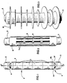
- Figure 1 very schematically shows an assembly comprising a stacking of varistor blocks between two armatures to constitute a insert.
- Figure 2 shows very schematically the assembly of Figure 1 fitted with a thermoplastic envelope, the outer surface of which an embossed structure.
- FIG. 3 shows very schematically the surge arrester according to the invention with its elastomeric polymer housing.
- the surge arrester or surge arrester according to the invention includes a set of electrically conductive components in the event of overvoltage, for example cylindrical blocks of varistor 1, aligned in row along a longitudinal axis 2 and in contact with each other by their appropriate end faces. On each end face of the stack of varistor blocks is placed a metal connection frame 3.
- Each frame 3 has an annular groove indicated by 4 which extends perpendicular to axis 2 and which has facets 4a, 4b, 4c giving in cross section to axis 2 a polygonal shape, for example hexagonal.
- an envelope 6 surrounds the varistor blocks 1 and the reinforcements 3.
- this envelope is made from a material thermoplastic and has an embossed outer surface with depressions 7 and bumps 8 and 9.
- thermoplastic material is molded on the outer surface of assembly 5 consisting of the stack of varistors 1 and the armatures metal 3.
- the casing 6 can be produced for example, by molding by injection of the thermoplastic material into an injection mold containing assembly 5 which avoids the risk of air or humidity inclusions between the varistor blocks and the envelope.
- Envelope 6 can also be prefabricated to be in the form of a tube made of material thermoplastic. Assembly 5 is introduced into the prefabricated envelope which is then compression molded, in a compression mold, onto the assembly 5 so as to obtain recesses 7 corresponding to zones thinner envelope.
- the envelope 6, at the level of these zones of thinner thickness is likely to rupture locally under significant gas pressure and side openings thus formed by rupture are used to vent the gas.
- the bumps on the outer surface of the casing 6 define longitudinal ribs 8 and radial 9 with respect to the axis 2. These ribs serve to constitute reinforcements to ensure the mechanical strength and the rigidity of the insert constituted by the assembly 5 and the envelope 6.
- assembly 5 is heated in an oven to bring its temperature to approximately 80 ° C so as to reduce, when the plastic material hardens, stresses due to differential expansion.
- the plastic material of the envelope fills the grooves 4 of reinforcements 3 so that the envelope engaged in these grooves ensures contact between the varistor blocks and prevents, due to the presence of facets, a rotational movement of the reinforcements 3 around the axis 2.
- This plastic material can advantageously be loaded with cut fiberglass or silica to increase its characteristics mechanical and self-extinguishing.
- a material thermoplastic with a very narrow melting point for example, a polyamide, a polyoxymethylene or even a polyphthalamide, to make the envelope.
- the envelope 6 of the insert is enclosed in a housing in elastomeric polymeric material 10 having annular fins.
- This case is advantageously produced by injection of the elastomeric polymer material in an injection mold containing the insert.
- This elastomeric polymer material comes to fill the recesses 7 of the surface of the envelope without risk of inclusion of gas or humidity between the casing 6 and the casing 10.
- the outer surface of the envelope is prepared, for example sanded to be frosted and glued.
Landscapes
- Engineering & Computer Science (AREA)
- Microelectronics & Electronic Packaging (AREA)
- Physics & Mathematics (AREA)
- Electromagnetism (AREA)
- Thermistors And Varistors (AREA)
- Injection Moulding Of Plastics Or The Like (AREA)
- Cable Accessories (AREA)
- Connector Housings Or Holding Contact Members (AREA)
- Gas Exhaust Devices For Batteries (AREA)
- Motor Or Generator Frames (AREA)
Abstract
Description
L'invention concerne un dériveur de surtension ou parafoudre comprenant deux armatures métalliques de raccordement, un empilement de composants électriques conducteurs s'étendant suivant un axe longitudinal entre les deux armatures, une enveloppe entourant les composants électriques et les armatures de telle sorte à maintenir un contact électrique entre ces composants.The invention relates to a surge arrester or surge arrester comprising two metal connection frames, a stack of conductive electrical components extending along a longitudinal axis between the two fittings, an envelope surrounding the electrical components and reinforcements so as to maintain electrical contact between these components.
Un tel dériveur de surtension ou parafoudre est destiné à être raccordé à des équipements électriques pour dériver les impulsions de surintensité. De telles impulsions de surintensité se présentent par exemple lors de coups de foudre. Lorsque ceci a lieu, le parafoudre dérive l'impulsion de surintensité à la terre, protégeant ainsi l'équipement électrique et le circuit de tout dommage ou destruction.Such a surge arrester or lightning arrester is intended to be connected to electrical equipment to derive the overcurrent pulses. Of such overcurrent pulses occur, for example, during strokes lightning. When this occurs, the arrester derives the overcurrent pulse at the earth, thereby protecting the electrical equipment and circuit from damage or destruction.
Le brevet américain n°3018406 décrit un parafoudre ayant une enveloppe en une matière thermodurcissable moulée sur les composants électriques. Pour éviter des inclusions de cette matière entre les composants électriques lors du moulage, les composants électriques sont protégés par deux demi-coquilles préfabriquées.U.S. Patent No. 3,018,406 describes a surge arrester having a casing in thermosetting material molded on components electric. To avoid inclusions of this material between the electrical components during molding, the electrical components are protected by two prefabricated half-shells.
Dans les parafoudres actuels décrits dans la demande de brevet français n°2685533, l'enveloppe entourant les composants électriques conducteurs, généralement des blocs cylindriques de varistance, est constituée par un enroulement de fibres de verre imprégné de résine, l'ensemble étant logé dans un boítier isolant en polymère élastomère étanche aux intempéries. Lorsqu'un parafoudre fonctionne correctement, un contact intime doit être maintenu entre les blocs de varistances. Ce contact est assuré par une structure d'enveloppe mettant en compression axiale les blocs de varistance. Le cas échéant, un ressort peut être interposé entre une armature et le bloc de varistance situé à l'extrémité correspondante de l'empilement pour réaliser cette compression axiale.In the current surge arresters described in the French patent application n ° 2685533, the envelope surrounding the conductive electrical components, generally cylindrical blocks of varistor, is constituted by a winding of resin-impregnated glass fibers, the assembly being housed in an insulating casing made of weatherproof elastomeric polymer. when surge arrester is working properly, intimate contact must be maintained between the varistor blocks. This contact is ensured by an envelope structure putting the varistor blocks in axial compression. If necessary, a spring can be interposed between a frame and the varistor block located at the corresponding end of the stack to achieve this compression axial.
Ces parafoudres sont susceptibles de présenter des défaillances et dans ce cas ils peuvent être soumis à des courants de fuite importants produisant des pressions de gaz élevées à l'intérieur de l'enveloppe ce qui conduit à l'éclatement du parafoudre. Pour limiter ou empêcher ce risque d'éclatement, il est connu du brevet européen n°0335480 de prévoir une enveloppe formée par un enroulement de fibres de verre laissant des ouvertures latérales de mise à l'air libre des gaz. Une telle construction s'avère toutefois relativement coûteuse à fabriquer. Dans la demande de brevet européen n°0595376, le parafoudre comporte une enveloppe préfabriquée en une matière thermodurcissable comme le polyester dans laquelle sont formées des ouvertures ou des zones de faible épaisseur pour l'échappement des gaz. Toutefois, la mise en compression axiale des éléments électriques ou blocs de varistance dans l'enveloppe doit être réalisée par un ressort.These surge arresters are likely to present failures and in in this case they may be subjected to large leakage currents producing high gas pressures inside the envelope which leads to the bursting of the arrester. To limit or prevent this risk of bursting, it is known from European Patent No. 0335480 to provide an envelope formed by a winding of glass fibers leaving lateral opening for opening the open air of gases. Such a construction is however relatively expensive to manufacture. In European patent application No. 0595376, the arrester has a prefabricated casing made of a thermosetting material such as polyester in which openings or areas of weakness are formed thickness for exhaust gas. However, the axial compression electrical elements or varistor blocks in the enclosure must be produced by a spring.
Le dériveur de surtension selon l'invention tel que défini par la revendication 1 remédie aux inconvénients indiqués ci-dessus.The overvoltage diverter according to the invention as defined by claim 1 remedies the drawbacks indicated above.
Une surpression des gaz à l'intérieur de l'enveloppe provoque donc la rupture de l'enveloppe au niveau de ses zones de plus faible épaisseur et donc de plus grande fragilité, c'est-à-dire au niveau des creux de la surface gaufrée, ce qui permet la mise à l'air des gaz par les ouvertures ainsi créées sans risque d'éclatement du parafoudre.An overpressure of the gases inside the envelope therefore causes the rupture of the envelope at its thinner areas and therefore of greater brittleness, that is to say at the level of the hollows of the embossed surface, which allows the venting of gases through the openings thus created without risk bursting lightning arrester.
Le dériveur selon l'invention est d'un faible coût de revient avec un temps de fabrication réduit. L'enveloppe d'un tel dériveur peut être réalisée par moulage par injection ou par compression de la matière thermoplastique sur les composants électriques et les armatures métalliques. Il est exempt d'inclusion d'air ou d'humidité entre les composants électriques et l'enveloppe ou entre l'enveloppe et le boítier en matière polymère élastomère qui entoure l'enveloppe. L'utilisation de la matière thermoplastique est particulièrement avantageux puisque cette matière a un temps de cycle très court. Par ailleurs, le moulage se faisant sur une colonne froide (les composants électriques dans le moule étant portés à une température d'environ 80°c tandis que la matière thermoplastique dans le moule étant à une température de fusion d'environ 270°c), cette matière thermoplastique, dont le point de fusion est généralement très étroit, a tendance à figer très rapidement au contact des composants électriques et ne s'introduit pas entre ces composants. Ainsi, il n'est pas nécessaire de protéger les composants électriques par un film servant à éviter l'inclusion de matière entre les composants électriques.The dinghy according to the invention is of low cost over time reduced manufacturing. The envelope of such a dinghy can be produced by molding by injection or compression of the thermoplastic material on the electrical components and metal fittings. It is free of inclusion air or humidity between the electrical components and the enclosure or between the envelope and the casing made of elastomeric polymer material which surrounds the envelope. The use of thermoplastic material is particularly advantageous since this material has a very short cycle time. Furthermore, the molding is making on a cold column (the electrical components in the mold being brought to a temperature of around 80 ° c while the thermoplastic material in the mold being at a melting temperature of about 270 ° c), this material thermoplastic, whose melting point is generally very narrow, tends to freeze very quickly on contact with electrical components and does not get in not between these components. So there is no need to protect electrical components by a film used to avoid the inclusion of material between electrical components.
D'autres caractéristiques et avantages de l'invention apparaítront encore à la lecture de la description qui suit d'un exemple de réalisation.Other characteristics and advantages of the invention will also appear on reading the following description of an exemplary embodiment.
La figure 1 montre très schématiquement un assemblage comprenant un empilement de blocs de varistance entre deux armatures pour constituer un insert.Figure 1 very schematically shows an assembly comprising a stacking of varistor blocks between two armatures to constitute a insert.
La figure 2 montre très schématiquement l'assemblage de la figure 1 muni d'une enveloppe en matière thermoplastique dont la surface extérieure a une structure gaufrée. Figure 2 shows very schematically the assembly of Figure 1 fitted with a thermoplastic envelope, the outer surface of which an embossed structure.
La figure 3 montre très schématiquement le dériveur de surtension selon l'invention avec son boítier en polymère élastomère.Figure 3 shows very schematically the surge arrester according to the invention with its elastomeric polymer housing.
Figure 1, le dériveur de surtension ou parafoudre selon l'invention
comprend un ensemble de composants électriques conducteurs en cas de
surtension, par exemple des blocs cylindriques de varistance 1, alignés en
rangée suivant un axe longitudinal 2 et en contact l'un avec l'autre par leurs
faces d'extrémité appropriées. Sur chaque face d'extrémité de l'empilement de
blocs de varistance est placée une armature métallique de raccordement 3.Figure 1, the surge arrester or surge arrester according to the invention
includes a set of electrically conductive components in the event of
overvoltage, for example cylindrical blocks of varistor 1, aligned in
row along a
Chaque armature 3 présente une gorge annulaire indiquée par 4 qui
s'étend perpendiculairement à l'axe 2 et qui présente des facettes 4a,4b,4c lui
conférant en coupe transversale à l'axe 2 une forme polygonale, par exemple
hexagonale.Each
Figure 2, une enveloppe 6 entoure les blocs de varistance 1 et les
armatures 3. Selon l'invention, cette enveloppe est réalisée à partir d'une matière
thermoplastique et présente une surface extérieure gaufrée avec des creux 7 et
des bosses 8 et 9.Figure 2, an envelope 6 surrounds the varistor blocks 1 and the
La matière thermoplastique est moulée sur la surface extérieure de
l'assemblage 5 constitué par l'empilement de varistances 1 et les armatures
métalliques 3. L'enveloppe 6 peut être réalisée par exemple, par moulage par
injection de la matière thermoplastique dans un moule d'injection contenant
l'assemblage 5 ce qui permet d'éviter les risques d'inclusions d'air ou d'humidité
entre les blocs de varistances et l'enveloppe. L'enveloppe 6 peut aussi être
préfabriquée pour se présenter sous la forme d'un tube en matière
thermoplastique. L'assemblage 5 est introduit dans l'enveloppe préfabriquée qui
est ensuite moulée par compression, dans un moule de compression, sur
l'assemblage 5 de telle sorte à obtenir des creux 7 correspondant à des zones
de plus faible épaisseur de l'enveloppe.The thermoplastic material is molded on the outer surface of
L'enveloppe 6, au niveau de ces zones de plus faible épaisseur est susceptible de se rompre localement sous une pression importante de gaz et les ouvertures latérales ainsi formées par rupture servent à la mise à l'air libre des gaz.The envelope 6, at the level of these zones of thinner thickness is likely to rupture locally under significant gas pressure and side openings thus formed by rupture are used to vent the gas.
Les bosses de la surface extérieure de l'enveloppe 6 définissent des
nervures longitudinales 8 et radiales 9 par rapport à l'axe 2. Ces nervures
servent à constituer des renforts pour assurer la tenue mécanique et la rigidité de
l'insert constitué par l'assemblage 5 et l'enveloppe 6.The bumps on the outer surface of the casing 6 define
longitudinal ribs 8 and radial 9 with respect to the
Pendant la réalisation de l'enveloppe 6 par moulage par injection ou par
compression de la matière thermoplastique sur l'assemblage 5, on exerce sur
chaque extrémité de l'assemblage 5, une force de compression F dirigée selon
l'axe 2 de façon à éviter un déplacement relatif entre les blocs de varistances 1
et les armatures 3 par rapport à l'axe longitudinal de l'empilement ainsi que
l'inclusion de la matière thermoplastique entre les blocs de varistances. Cette
force de compression est de l'ordre de 100 N.During the production of the envelope 6 by injection molding or by
compression of the thermoplastic material on the
Avant la réalisation de l'enveloppe en matière thermoplastique,
l'assemblage 5 est chauffé dans un four pour porter sa température à environ
80°C de sorte à diminuer, lors du durcissement de la matière plastique, les
efforts dus à la dilatation différentielle.Before making the thermoplastic envelope,
La matière plastique de l'enveloppe vient remplir les gorges 4 des
armatures 3 de sorte que l'enveloppe en prise dans ces gorges assure le contact
électrique entre les blocs de varistances et empêche, du fait de la présence des
facettes, un déplacement en rotation des armatures 3 autour de l'axe 2.The plastic material of the envelope fills the grooves 4 of
Cette matière plastique peut avantageusement être chargée avec de la fibre de verre coupée ou de la silice pour augmenter ses caractéristiques mécaniques et d'auto extinction. De préférence, on utilisera une matière thermoplastique à point de fusion très étroit, par exemple, un polyamide, un polyoxyméthylène ou encore un polyphtalamide, pour réaliser l'enveloppe.This plastic material can advantageously be loaded with cut fiberglass or silica to increase its characteristics mechanical and self-extinguishing. Preferably, we will use a material thermoplastic with a very narrow melting point, for example, a polyamide, a polyoxymethylene or even a polyphthalamide, to make the envelope.
Figure 3, l'enveloppe 6 de l'insert est enfermée dans un boítier en
matière polymère élastomère 10 présentant des ailettes annulaires. Ce boítier
est avantageusement réalisé par injection de la matière polymère élastomère
dans un moule d'injection contenant l'insert. Cette matière polymère élastomère
vient remplir les creux 7 de la surface de l'enveloppe sans risque d'inclusion de
gaz ou d'humidité entre l'enveloppe 6 et le boítier 10.Figure 3, the envelope 6 of the insert is enclosed in a housing in
elastomeric
Avant de réaliser ce boítier, la surface extérieure de l'enveloppe est préparée, par exemple sablée pour être dépolie et encollée.Before making this case, the outer surface of the envelope is prepared, for example sanded to be frosted and glued.
Claims (8)
- An overvoltage-diverter comprising two metal connecting fittings (3), a stack of electrical components (1) extending along a longitudinal axis (2) between the two fittings, an envelope (6) surrounding the electrical components and the fittings in such a way as to maintain electrical contact between the said components, the envelope being moulded over the electrical components and fittings, characterised in that the envelope is produced from a thermoplastic material and in that the said envelope has a corrugated outer surface with hollows (7) and bosses (8, 9), the hollows corresponding to zones of lower thickness in the envelope which are liable to break locally under major gas pressure so as to constitute, after breaking, lateral openings in the envelope for the venting of gas.
- The diverter according to claim 1, wherein each metal fitting (3) has an annular groove (4) with facets (4a, 4b, 4c), in which the envelope grips.
- The diverter according to one of claims 1 to 2, wherein the bosses on the corrugated outer surface of the envelope (6) constitute ribs which are longitudinal (8) and ribs which are radial (9) in relation to the said axis (2).
- The diverter according to one of claims 1 to 3, comprising a casing (10) of elastomeric polymer material surrounding the envelope, the said polymer material filling up the hollows (7) in the outer surface of the envelope.
- A process for manufacturing a diverter according to any of claims 1 to 4, wherein the envelope is moulded over the electrical components (1) and the metal fittings (3) by injection of the thermoplastic material into a mould containing the stack of electrical components (1) between the two fittings (3), the said stack of electrical components being subjected to a compressive force (F) exerted along the said longitudinal axis (2) during the injection of the thermoplastic material.
- A process for manufacturing an overvoltage diverter according to any of claims 1 to 4, wherein the envelope is moulded over the electrical components (1) and the metal fittings (3) by compression of the thermoplastic material in a mould containing the stack of electrical components (1) between the two fittings (3), the said stack of electrical components being subjected to a compressive force (F) exerted along the said longitudinal axis (2) during the compression of the thermoplastic material.
- The process according to one of claims 5 or 6, wherein the stack of electrical components (1) between the two fittings (3) is first of all heated prior to the moulding of the thermoplastic material over the electrical components and the fittings.
- The process according to claim 7, wherein a casing of elastomeric polymer material (10) is moulded by injection round the envelope (6), the said elastomeric polymer material filling up the hollows (7) in the outer surface of the envelope.
Applications Claiming Priority (2)
| Application Number | Priority Date | Filing Date | Title |
|---|---|---|---|
| FR9615852 | 1996-12-23 | ||
| FR9615852A FR2757693B1 (en) | 1996-12-23 | 1996-12-23 | SURGE PROTECTOR WITH ENVELOPE HAVING EMBOSSED OUTER SURFACE |
Publications (2)
| Publication Number | Publication Date |
|---|---|
| EP0851549A1 EP0851549A1 (en) | 1998-07-01 |
| EP0851549B1 true EP0851549B1 (en) | 2003-03-26 |
Family
ID=9499001
Family Applications (1)
| Application Number | Title | Priority Date | Filing Date |
|---|---|---|---|
| EP97403081A Expired - Lifetime EP0851549B1 (en) | 1996-12-23 | 1997-12-18 | Surge arrester having a housing made from thermoplastic material with an external wafer form surface |
Country Status (11)
| Country | Link |
|---|---|
| US (1) | US5875090A (en) |
| EP (1) | EP0851549B1 (en) |
| CN (1) | CN1111877C (en) |
| AT (1) | ATE235754T1 (en) |
| BR (1) | BR9706425B1 (en) |
| CA (1) | CA2225625C (en) |
| DE (1) | DE69720169T2 (en) |
| DK (1) | DK0851549T3 (en) |
| ES (1) | ES2192660T3 (en) |
| FR (1) | FR2757693B1 (en) |
| ZA (1) | ZA9711512B (en) |
Families Citing this family (5)
| Publication number | Priority date | Publication date | Assignee | Title |
|---|---|---|---|---|
| US6625280B1 (en) | 1999-11-01 | 2003-09-23 | Avaya Technology Corp. | Balanced heat coil protector |
| SG105003A1 (en) * | 2002-04-15 | 2004-07-30 | Andrew Corp | Surge lightning protection device |
| ITPD20030228A1 (en) * | 2003-10-01 | 2005-04-02 | Comem Spa | STRUCTURE OF OVERVOLTAGE UNLOADER |
| DE102005007146A1 (en) * | 2005-02-11 | 2006-08-24 | Siemens Ag | Method for sheathing a varistor block with an electrically insulating sheath and varistor block for a surge arrester |
| EP2998970B1 (en) * | 2014-09-22 | 2017-08-02 | Siemens Aktiengesellschaft | Surge arrester |
Citations (1)
| Publication number | Priority date | Publication date | Assignee | Title |
|---|---|---|---|---|
| US3018406A (en) * | 1958-07-17 | 1962-01-23 | Westinghouse Electric Corp | Lightning arrester |
Family Cites Families (7)
| Publication number | Priority date | Publication date | Assignee | Title |
|---|---|---|---|---|
| AU595433B2 (en) * | 1987-03-06 | 1990-03-29 | Societe Anonyme Dite Ceraver | A method of manufacturing a lightning arrester, and a lightning arrester obtained by the method |
| SE459294B (en) * | 1987-10-26 | 1989-06-19 | Asea Ab | surge |
| JP3012884B2 (en) * | 1988-02-17 | 2000-02-28 | 音羽電機工業株式会社 | Surge arrester |
| CA1334990C (en) * | 1988-03-31 | 1995-03-28 | John D. Sakich | Modular electrical assemblies with pressure relief |
| US4930039A (en) * | 1989-04-18 | 1990-05-29 | Cooper Industries, Inc. | Fail-safe surge arrester |
| US5128824A (en) * | 1991-02-20 | 1992-07-07 | Amerace Corporation | Directionally vented underground distribution surge arrester |
| FR2685533B1 (en) * | 1991-12-20 | 1994-04-01 | Soule | SURGE PROTECTOR COMPRISING AN IMPROVED CONTACT PART. |
-
1996
- 1996-12-23 FR FR9615852A patent/FR2757693B1/en not_active Expired - Fee Related
-
1997
- 1997-12-15 CA CA002225625A patent/CA2225625C/en not_active Expired - Fee Related
- 1997-12-18 DE DE69720169T patent/DE69720169T2/en not_active Expired - Lifetime
- 1997-12-18 DK DK97403081T patent/DK0851549T3/en active
- 1997-12-18 EP EP97403081A patent/EP0851549B1/en not_active Expired - Lifetime
- 1997-12-18 AT AT97403081T patent/ATE235754T1/en active
- 1997-12-18 ES ES97403081T patent/ES2192660T3/en not_active Expired - Lifetime
- 1997-12-19 BR BRPI9706425-4A patent/BR9706425B1/en not_active IP Right Cessation
- 1997-12-19 US US08/994,856 patent/US5875090A/en not_active Expired - Lifetime
- 1997-12-22 ZA ZA9711512A patent/ZA9711512B/en unknown
- 1997-12-22 CN CN97125916A patent/CN1111877C/en not_active Expired - Fee Related
Patent Citations (1)
| Publication number | Priority date | Publication date | Assignee | Title |
|---|---|---|---|---|
| US3018406A (en) * | 1958-07-17 | 1962-01-23 | Westinghouse Electric Corp | Lightning arrester |
Also Published As
| Publication number | Publication date |
|---|---|
| DE69720169D1 (en) | 2003-04-30 |
| US5875090A (en) | 1999-02-23 |
| ZA9711512B (en) | 1999-06-22 |
| EP0851549A1 (en) | 1998-07-01 |
| BR9706425A (en) | 1999-05-25 |
| CN1194443A (en) | 1998-09-30 |
| BR9706425B1 (en) | 2011-05-31 |
| CA2225625C (en) | 2007-03-20 |
| ES2192660T3 (en) | 2003-10-16 |
| DK0851549T3 (en) | 2003-07-21 |
| MX9710348A (en) | 1998-08-30 |
| CA2225625A1 (en) | 1998-06-23 |
| CN1111877C (en) | 2003-06-18 |
| FR2757693A1 (en) | 1998-06-26 |
| ATE235754T1 (en) | 2003-04-15 |
| DE69720169T2 (en) | 2004-01-15 |
| FR2757693B1 (en) | 1999-02-19 |
Similar Documents
| Publication | Publication Date | Title |
|---|---|---|
| EP0605265B1 (en) | Arresters on varistor basis, in particular for high voltages | |
| EP2223319B1 (en) | Insulation of a current interrupter of the vacuum bulb type by overmoulding | |
| CA1310811C (en) | Lightning arrester and method of manufacturing same | |
| CA2016590C (en) | Sealed winding based envelope, and composite lightning arrestor using same | |
| EP0958584B1 (en) | Enhanced varistor-based lighting arresters | |
| EP0413618B1 (en) | Surge arrester with movable supports to maintain its varistors | |
| CA1305513C (en) | Lightning arrester and fabrication process thereof | |
| US4962440A (en) | Surge arrester | |
| EP0851549B1 (en) | Surge arrester having a housing made from thermoplastic material with an external wafer form surface | |
| CA2356383C (en) | Improved lightning arrestor based on electrical varistors | |
| CA1263162A (en) | Electrical device casing, namely a lightning arrester, incorporating a moulded insulating enveloppe | |
| KR100479523B1 (en) | Module of polymer arrester using a braid and manufacturing method thereof | |
| WO1996013043A1 (en) | Lightning arrester device | |
| JP3621930B2 (en) | Method of manufacturing a lightning arrester | |
| JP3376774B2 (en) | Lightning arrester and method of manufacturing lightning arrester | |
| EP0874374B1 (en) | Electrical resistance as resistive flexible belt and apparatus using said resistance | |
| JP3665416B2 (en) | Lightning arrestor | |
| EP0779635B1 (en) | Power capacitor | |
| JP2003303706A (en) | Arrester | |
| MXPA97010348A (en) | A stopper with a thermoplastic envelope that has a realized outer surface | |
| JP3546576B2 (en) | Surge arrester | |
| EP0459873B1 (en) | Solid electrolyte capacitor, namely tantalum capacitor, with stamped incorporated fuse and process for its manufacturing | |
| CN101320606A (en) | Improvements on surge arresters | |
| JP2005515626A (en) | Overvoltage arrester | |
| JPH1140311A (en) | Arrester |
Legal Events
| Date | Code | Title | Description |
|---|---|---|---|
| PUAI | Public reference made under article 153(3) epc to a published international application that has entered the european phase |
Free format text: ORIGINAL CODE: 0009012 |
|
| AK | Designated contracting states |
Kind code of ref document: A1 Designated state(s): AT BE CH DE DK ES FR GB IT LI NL SE |
|
| AX | Request for extension of the european patent |
Free format text: AL;LT;LV;MK;RO;SI |
|
| 17P | Request for examination filed |
Effective date: 19980801 |
|
| AKX | Designation fees paid |
Free format text: AT BE CH DE DK ES FR GB IT LI NL SE |
|
| RBV | Designated contracting states (corrected) |
Designated state(s): AT BE CH DE DK ES FR GB IT LI NL SE |
|
| 17Q | First examination report despatched |
Effective date: 20010320 |
|
| GRAH | Despatch of communication of intention to grant a patent |
Free format text: ORIGINAL CODE: EPIDOS IGRA |
|
| GRAH | Despatch of communication of intention to grant a patent |
Free format text: ORIGINAL CODE: EPIDOS IGRA |
|
| GRAA | (expected) grant |
Free format text: ORIGINAL CODE: 0009210 |
|
| AK | Designated contracting states |
Designated state(s): AT BE CH DE DK ES FR GB IT LI NL SE |
|
| REG | Reference to a national code |
Ref country code: GB Ref legal event code: FG4D Free format text: NOT ENGLISH |
|
| REG | Reference to a national code |
Ref country code: CH Ref legal event code: EP |
|
| REF | Corresponds to: |
Ref document number: 69720169 Country of ref document: DE Date of ref document: 20030430 Kind code of ref document: P |
|
| REG | Reference to a national code |
Ref country code: CH Ref legal event code: NV Representative=s name: ALTHOFF PATENTANWALTSBUERO |
|
| REG | Reference to a national code |
Ref country code: SE Ref legal event code: TRGR |
|
| REG | Reference to a national code |
Ref country code: DK Ref legal event code: T3 |
|
| GBT | Gb: translation of ep patent filed (gb section 77(6)(a)/1977) |
Effective date: 20030723 |
|
| REG | Reference to a national code |
Ref country code: ES Ref legal event code: FG2A Ref document number: 2192660 Country of ref document: ES Kind code of ref document: T3 |
|
| PLBE | No opposition filed within time limit |
Free format text: ORIGINAL CODE: 0009261 |
|
| STAA | Information on the status of an ep patent application or granted ep patent |
Free format text: STATUS: NO OPPOSITION FILED WITHIN TIME LIMIT |
|
| 26N | No opposition filed |
Effective date: 20031230 |
|
| REG | Reference to a national code |
Ref country code: FR Ref legal event code: PLFP Year of fee payment: 19 |
|
| PGFP | Annual fee paid to national office [announced via postgrant information from national office to epo] |
Ref country code: GB Payment date: 20151221 Year of fee payment: 19 Ref country code: DK Payment date: 20151221 Year of fee payment: 19 Ref country code: CH Payment date: 20151221 Year of fee payment: 19 Ref country code: DE Payment date: 20151211 Year of fee payment: 19 |
|
| PGFP | Annual fee paid to national office [announced via postgrant information from national office to epo] |
Ref country code: SE Payment date: 20151221 Year of fee payment: 19 Ref country code: BE Payment date: 20151221 Year of fee payment: 19 Ref country code: ES Payment date: 20151214 Year of fee payment: 19 Ref country code: NL Payment date: 20151221 Year of fee payment: 19 Ref country code: AT Payment date: 20151222 Year of fee payment: 19 Ref country code: FR Payment date: 20151214 Year of fee payment: 19 |
|
| PGFP | Annual fee paid to national office [announced via postgrant information from national office to epo] |
Ref country code: IT Payment date: 20151228 Year of fee payment: 19 |
|
| PG25 | Lapsed in a contracting state [announced via postgrant information from national office to epo] |
Ref country code: BE Free format text: LAPSE BECAUSE OF NON-PAYMENT OF DUE FEES Effective date: 20161231 |
|
| REG | Reference to a national code |
Ref country code: DE Ref legal event code: R119 Ref document number: 69720169 Country of ref document: DE |
|
| REG | Reference to a national code |
Ref country code: CH Ref legal event code: PL Ref country code: DK Ref legal event code: EBP Effective date: 20161231 |
|
| REG | Reference to a national code |
Ref country code: SE Ref legal event code: EUG |
|
| REG | Reference to a national code |
Ref country code: NL Ref legal event code: MM Effective date: 20170101 |
|
| REG | Reference to a national code |
Ref country code: AT Ref legal event code: MM01 Ref document number: 235754 Country of ref document: AT Kind code of ref document: T Effective date: 20161218 |
|
| GBPC | Gb: european patent ceased through non-payment of renewal fee |
Effective date: 20161218 |
|
| PG25 | Lapsed in a contracting state [announced via postgrant information from national office to epo] |
Ref country code: SE Free format text: LAPSE BECAUSE OF NON-PAYMENT OF DUE FEES Effective date: 20161219 |
|
| PG25 | Lapsed in a contracting state [announced via postgrant information from national office to epo] |
Ref country code: NL Free format text: LAPSE BECAUSE OF NON-PAYMENT OF DUE FEES Effective date: 20170101 |
|
| REG | Reference to a national code |
Ref country code: FR Ref legal event code: ST Effective date: 20170831 |
|
| PG25 | Lapsed in a contracting state [announced via postgrant information from national office to epo] |
Ref country code: FR Free format text: LAPSE BECAUSE OF NON-PAYMENT OF DUE FEES Effective date: 20170102 Ref country code: LI Free format text: LAPSE BECAUSE OF NON-PAYMENT OF DUE FEES Effective date: 20161231 Ref country code: IT Free format text: LAPSE BECAUSE OF NON-PAYMENT OF DUE FEES Effective date: 20161218 Ref country code: AT Free format text: LAPSE BECAUSE OF NON-PAYMENT OF DUE FEES Effective date: 20161218 Ref country code: CH Free format text: LAPSE BECAUSE OF NON-PAYMENT OF DUE FEES Effective date: 20161231 |
|
| PG25 | Lapsed in a contracting state [announced via postgrant information from national office to epo] |
Ref country code: DE Free format text: LAPSE BECAUSE OF NON-PAYMENT OF DUE FEES Effective date: 20170701 Ref country code: GB Free format text: LAPSE BECAUSE OF NON-PAYMENT OF DUE FEES Effective date: 20161218 |
|
| PG25 | Lapsed in a contracting state [announced via postgrant information from national office to epo] |
Ref country code: DK Free format text: LAPSE BECAUSE OF NON-PAYMENT OF DUE FEES Effective date: 20161231 |
|
| REG | Reference to a national code |
Ref country code: BE Ref legal event code: MM Effective date: 20161231 |
|
| REG | Reference to a national code |
Ref country code: ES Ref legal event code: FD2A Effective date: 20180507 |
|
| PG25 | Lapsed in a contracting state [announced via postgrant information from national office to epo] |
Ref country code: ES Free format text: LAPSE BECAUSE OF FAILURE TO SUBMIT A TRANSLATION OF THE DESCRIPTION OR TO PAY THE FEE WITHIN THE PRESCRIBED TIME-LIMIT Effective date: 20030326 |
|
| PG25 | Lapsed in a contracting state [announced via postgrant information from national office to epo] |
Ref country code: ES Free format text: LAPSE BECAUSE OF FAILURE TO SUBMIT A TRANSLATION OF THE DESCRIPTION OR TO PAY THE FEE WITHIN THE PRESCRIBED TIME-LIMIT Effective date: 20161219 |
|
| RIC2 | Information provided on ipc code assigned after grant |
Ipc: H01C 7/12 20060101ALI19980217BHEP Ipc: H01T 1/15 20060101AFI19980217BHEP |