EP0851181A2 - Wärmespeicher und Brennstoffspareinrichtung für Gasheizkessel - Google Patents
Wärmespeicher und Brennstoffspareinrichtung für Gasheizkessel Download PDFInfo
- Publication number
- EP0851181A2 EP0851181A2 EP97500224A EP97500224A EP0851181A2 EP 0851181 A2 EP0851181 A2 EP 0851181A2 EP 97500224 A EP97500224 A EP 97500224A EP 97500224 A EP97500224 A EP 97500224A EP 0851181 A2 EP0851181 A2 EP 0851181A2
- Authority
- EP
- European Patent Office
- Prior art keywords
- bars
- gas
- heating boilers
- saving
- domestic heating
- Prior art date
- Legal status (The legal status is an assumption and is not a legal conclusion. Google has not performed a legal analysis and makes no representation as to the accuracy of the status listed.)
- Withdrawn
Links
- 238000010438 heat treatment Methods 0.000 claims abstract description 17
- 238000002485 combustion reaction Methods 0.000 claims abstract description 16
- 238000002347 injection Methods 0.000 claims abstract description 7
- 239000007924 injection Substances 0.000 claims abstract description 7
- 229910001018 Cast iron Inorganic materials 0.000 claims abstract description 5
- ZZUFCTLCJUWOSV-UHFFFAOYSA-N furosemide Chemical compound C1=C(Cl)C(S(=O)(=O)N)=CC(C(O)=O)=C1NCC1=CC=CO1 ZZUFCTLCJUWOSV-UHFFFAOYSA-N 0.000 claims abstract description 3
- 238000000926 separation method Methods 0.000 claims description 3
- 239000000446 fuel Substances 0.000 abstract description 8
- XEEYBQQBJWHFJM-UHFFFAOYSA-N Iron Chemical compound [Fe] XEEYBQQBJWHFJM-UHFFFAOYSA-N 0.000 abstract 1
- 238000010924 continuous production Methods 0.000 abstract 1
- 239000002826 coolant Substances 0.000 abstract 1
- XLYOFNOQVPJJNP-UHFFFAOYSA-N water Substances O XLYOFNOQVPJJNP-UHFFFAOYSA-N 0.000 description 4
- 230000004308 accommodation Effects 0.000 description 2
- 238000011109 contamination Methods 0.000 description 2
- 230000000694 effects Effects 0.000 description 2
- 238000009434 installation Methods 0.000 description 2
- 238000005259 measurement Methods 0.000 description 2
- 238000012360 testing method Methods 0.000 description 2
- 230000004913 activation Effects 0.000 description 1
- 230000006399 behavior Effects 0.000 description 1
- 239000012141 concentrate Substances 0.000 description 1
- 238000001816 cooling Methods 0.000 description 1
- 238000010586 diagram Methods 0.000 description 1
- 230000009977 dual effect Effects 0.000 description 1
- 230000005611 electricity Effects 0.000 description 1
- 230000003203 everyday effect Effects 0.000 description 1
- 239000012530 fluid Substances 0.000 description 1
- 239000003517 fume Substances 0.000 description 1
- 239000013529 heat transfer fluid Substances 0.000 description 1
- 239000008236 heating water Substances 0.000 description 1
- 230000006698 induction Effects 0.000 description 1
- 238000004519 manufacturing process Methods 0.000 description 1
- 239000000463 material Substances 0.000 description 1
- 239000002184 metal Substances 0.000 description 1
- 229910052751 metal Inorganic materials 0.000 description 1
- 238000012986 modification Methods 0.000 description 1
- 230000004048 modification Effects 0.000 description 1
- 238000013021 overheating Methods 0.000 description 1
- 230000000750 progressive effect Effects 0.000 description 1
- 238000009423 ventilation Methods 0.000 description 1
- 239000002699 waste material Substances 0.000 description 1
- 230000003313 weakening effect Effects 0.000 description 1
Images
Classifications
-
- F—MECHANICAL ENGINEERING; LIGHTING; HEATING; WEAPONS; BLASTING
- F24—HEATING; RANGES; VENTILATING
- F24H—FLUID HEATERS, e.g. WATER OR AIR HEATERS, HAVING HEAT-GENERATING MEANS, e.g. HEAT PUMPS, IN GENERAL
- F24H7/00—Storage heaters, i.e. heaters in which the energy is stored as heat in masses for subsequent release
- F24H7/02—Storage heaters, i.e. heaters in which the energy is stored as heat in masses for subsequent release the released heat being conveyed to a transfer fluid
- F24H7/04—Storage heaters, i.e. heaters in which the energy is stored as heat in masses for subsequent release the released heat being conveyed to a transfer fluid with forced circulation of the transfer fluid
- F24H7/045—Storage heaters, i.e. heaters in which the energy is stored as heat in masses for subsequent release the released heat being conveyed to a transfer fluid with forced circulation of the transfer fluid using fluid fuel
- F24H7/0466—Storage heaters, i.e. heaters in which the energy is stored as heat in masses for subsequent release the released heat being conveyed to a transfer fluid with forced circulation of the transfer fluid using fluid fuel the transfer fluid being water
-
- F—MECHANICAL ENGINEERING; LIGHTING; HEATING; WEAPONS; BLASTING
- F23—COMBUSTION APPARATUS; COMBUSTION PROCESSES
- F23M—CASINGS, LININGS, WALLS OR DOORS SPECIALLY ADAPTED FOR COMBUSTION CHAMBERS, e.g. FIREBRIDGES; DEVICES FOR DEFLECTING AIR, FLAMES OR COMBUSTION PRODUCTS IN COMBUSTION CHAMBERS; SAFETY ARRANGEMENTS SPECIALLY ADAPTED FOR COMBUSTION APPARATUS; DETAILS OF COMBUSTION CHAMBERS, NOT OTHERWISE PROVIDED FOR
- F23M20/00—Details of combustion chambers, not otherwise provided for, e.g. means for storing heat from flames
-
- F—MECHANICAL ENGINEERING; LIGHTING; HEATING; WEAPONS; BLASTING
- F24—HEATING; RANGES; VENTILATING
- F24H—FLUID HEATERS, e.g. WATER OR AIR HEATERS, HAVING HEAT-GENERATING MEANS, e.g. HEAT PUMPS, IN GENERAL
- F24H1/00—Water heaters, e.g. boilers, continuous-flow heaters or water-storage heaters
- F24H1/22—Water heaters other than continuous-flow or water-storage heaters, e.g. water heaters for central heating
- F24H1/24—Water heaters other than continuous-flow or water-storage heaters, e.g. water heaters for central heating with water mantle surrounding the combustion chamber or chambers
- F24H1/26—Water heaters other than continuous-flow or water-storage heaters, e.g. water heaters for central heating with water mantle surrounding the combustion chamber or chambers the water mantle forming an integral body
- F24H1/28—Water heaters other than continuous-flow or water-storage heaters, e.g. water heaters for central heating with water mantle surrounding the combustion chamber or chambers the water mantle forming an integral body including one or more furnace or fire tubes
- F24H1/285—Water heaters other than continuous-flow or water-storage heaters, e.g. water heaters for central heating with water mantle surrounding the combustion chamber or chambers the water mantle forming an integral body including one or more furnace or fire tubes with the fire tubes arranged alongside the combustion chamber
Definitions
- the invention relates, according to the title thereof, to a glowing thermal storage device for everything kind of domestic (or industrial) boilers, rather than diesel, either by injection, watering or analog having the dual mission and the advantage of focus and accumulate the calories produced by the burner, at the same time obtaining maximum use fuel.
- the invention is a very simple apparatus which accomplishes a very well studied cycle of practical behavior, in avoiding the weakening or wasting of calories generated by the burner of a boiler of this kind, in depending on the fuel it should consume for generate.
- the calories are directly absorbed and accumulated by the device which is the subject of the invention, at the same time producing the maximum use of the combustible and a very low residual index, as well with regard to the material not consumed (burnt) that regarding fumes.
- this kind of devices relate to a specific model of boilers or heating because either they are designed for a concrete type of boilers existing on the market or they exit from the factory by incorporating it.
- the device which is the subject of the invention can advantageously, in principle, be installed in any what type of boiler, since the measurements can fit any model and obviously can also adapt directly to new ones production at the factory.
- a simple device with the characteristics of the invention allows better and faster heating heating fluid (water) and consumption of lower fuel, a higher residual coefficient low and a considerable reduction in consumption (mathematical logical proportion when the faster activation of the regulator thermostat room temperature, this being exceeded more easily).
- the apparatus of the invention has been tested in a typical ROCA boiler, VR-12.
- the regulator of the boiler In an accommodation of 80 square meters, we put the regulator of the boiler at point 1, the heating water has exceeded 45 ° C of temperature. Average consumption per hour has not was more than 0.60 liter, although we left cool the water every day for a few hours heating and that we put the said regulator in point 2 until the burner object of the invention is was heating up.
- Another advantage is the fact that with this system the price of the boiler does not rise.
- the apparatus which is the subject of the invention is a single metal piece of cast iron (preferably) which is provided with a discoid base with a thickness of approximately one centimeter who can have leverage to be adjusted to the combustion chamber and from which are projected perpendicularly from multiple rods massive cylindrical, also, preferably, of cast iron, which are held together at the base and being evenly distributed horizontally and radially but misaligned in the latter projection.
- the length of the rods is approximately the length of the combustion, staying a short distance from the burner and may vary its longitude from the dimensions of the burner, so that the flame enters axially between the central rods of the accumulator extending radially to the rest which absorbs the thermal effluent in accumulating it and concentrating it. Induction allows quickly heat the heat transfer fluid (water) and its ability to concentrate extends for longer said irradiation or said cooling of the boiler.
- Another detail of the invention is the fact that the thickness or section of the bars is the same in all these, and preferably cone-shaped to facilitate its release.
- outer ring is dimensioned and circularly spaced between the bars, so as to be able to engage between the striations from the combustion chamber of the boilers injection like this.
- said ring exterior is also dimensioned and for the same purpose as the previous one, while the second outer ring, concentric to the first, is dimensioned and spaced circularly to bear tangentially against the horizontal edge of the ribs in the combustion of sprinkler boilers (drip).
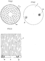
- Figure 1 is a top plan view of the apparatus according to the invention.
- Figure 2 is a vertical projection view by compared to Figure 1 with sectioned details of the mounting bars.
- Figure 3 is a 180 ° plan view of the figure 2.
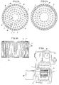
- Figure 1A is a top plan view of the apparatus, according to the invention, mounted in a combustion of an injection boiler.
- Figure 2A is equal to the previous one, installed in the combustion chamber of a sprinkler.
- FIG. 3A is a view in vertical projection of said appliance installed in a combustion chamber having air feeders.
- Figure 4 is a side detail of the installation of said devices in the general diagram of a boiler.
- the device consists of the circular base (2) in cast iron (preferably) with or without pressure means to the assembly and on which a battery of cylindrical bars (3), preferably cone-shaped and with equal diameter or section (d), distributed on rings concentric circulars where the separation or the radial (r) and horizontal (h) equidistance of these bars (3) between them, is equal to the diameter (d) thereof., although resulting partially misaligned in the radial projection and those of the inner ring having variable longitude.
- FIG. 1A An example of installation of the device in the combustion chamber (1) for an injection boiler (Fig. 1A) shows how the outer ring (4) of the bars (3) is included or engaged in the incisions (7) of said chamber (1).
- the bars (5) of the ring outside are distributed and spaced so that properly engage in said incisions (7) between streaks or ribs (8).
- the second ring (5) of bars (3) immediately concentric to the first is also distributed and spaced so that the bars (3) are supported tangentially against the interior plane (8a) of the ridges (8) of the combustion chamber (1).
- the central ring (6) frames a central zone (6A) free by where enters the burner flame by heating the bars (3) internal rings to facilitate this progressive overheating from the inside to the outside.
- the thermal accumulator (2) (3) is located having the base (2) against the bottom of the combustion chamber (1) in presenting the central space (6A) directly connected to the nozzle (11) of the burner (12).
Landscapes
- Engineering & Computer Science (AREA)
- Chemical & Material Sciences (AREA)
- Combustion & Propulsion (AREA)
- Mechanical Engineering (AREA)
- General Engineering & Computer Science (AREA)
- Physics & Mathematics (AREA)
- Thermal Sciences (AREA)
- Combustion Of Fluid Fuel (AREA)
- Spray-Type Burners (AREA)
Applications Claiming Priority (2)
| Application Number | Priority Date | Filing Date | Title |
|---|---|---|---|
| ES9602753 | 1996-12-27 | ||
| ES009602753A ES2138515B1 (es) | 1996-12-27 | 1996-12-27 | Acumulador termico y economizador para calderas de calefaccion domesticas a gasoil. |
Publications (2)
| Publication Number | Publication Date |
|---|---|
| EP0851181A2 true EP0851181A2 (de) | 1998-07-01 |
| EP0851181A3 EP0851181A3 (de) | 1999-11-10 |
Family
ID=8297170
Family Applications (1)
| Application Number | Title | Priority Date | Filing Date |
|---|---|---|---|
| EP97500224A Withdrawn EP0851181A3 (de) | 1996-12-27 | 1997-12-23 | Wärmespeicher und Brennstoffspareinrichtung für Gasheizkessel |
Country Status (2)
| Country | Link |
|---|---|
| EP (1) | EP0851181A3 (de) |
| ES (1) | ES2138515B1 (de) |
Cited By (2)
| Publication number | Priority date | Publication date | Assignee | Title |
|---|---|---|---|---|
| CN103245056A (zh) * | 2013-04-18 | 2013-08-14 | 苏州艾克玛能源科技有限公司 | 堆叠式集热装置 |
| CN107002996A (zh) * | 2014-11-26 | 2017-08-01 | 伊拉里奥·布兰科戈麦斯 | 用于锅炉的辐射热室 |
Family Cites Families (4)
| Publication number | Priority date | Publication date | Assignee | Title |
|---|---|---|---|---|
| DE1751564A1 (de) * | 1968-03-29 | 1971-07-08 | Manfred Walz Fa | Gluehkoerper |
| EP0028830A1 (de) * | 1979-11-12 | 1981-05-20 | Huber, Markus Gerätebau | Zentralheizungskessel mit spiralförmigen, stufenlos verstellbaren Heizflächen und von Aussen bedienbarer Reinigung |
| HU186793B (en) * | 1981-11-16 | 1985-09-30 | Laszlo Toth | Local heating equipment |
| SE444854B (sv) * | 1984-07-31 | 1986-05-12 | Smart & Simple Energy Systems | Markvermeackumulator |
-
1996
- 1996-12-27 ES ES009602753A patent/ES2138515B1/es not_active Expired - Fee Related
-
1997
- 1997-12-23 EP EP97500224A patent/EP0851181A3/de not_active Withdrawn
Cited By (3)
| Publication number | Priority date | Publication date | Assignee | Title |
|---|---|---|---|---|
| CN103245056A (zh) * | 2013-04-18 | 2013-08-14 | 苏州艾克玛能源科技有限公司 | 堆叠式集热装置 |
| CN103245056B (zh) * | 2013-04-18 | 2016-05-18 | 苏州艾克玛能源科技有限公司 | 堆叠式集热装置 |
| CN107002996A (zh) * | 2014-11-26 | 2017-08-01 | 伊拉里奥·布兰科戈麦斯 | 用于锅炉的辐射热室 |
Also Published As
| Publication number | Publication date |
|---|---|
| EP0851181A3 (de) | 1999-11-10 |
| ES2138515B1 (es) | 2000-08-16 |
| ES2138515A1 (es) | 2000-01-01 |
Similar Documents
| Publication | Publication Date | Title |
|---|---|---|
| FR2913105A1 (fr) | "echangeur de chaleur a condensation comprenant deux faisceaux primaires et un faisceau secondaire" | |
| EP2396607A2 (de) | Sonnenkollektor und energieerzeugungsanlage mit solchen sonnenkollektoren | |
| FR2948991A1 (fr) | Dispositif thermodynamique multi-energie modulaire | |
| CH639187A5 (fr) | Chaudiere, notamment pour installation de chauffage. | |
| FR2576404A1 (fr) | Echangeur de chaleur et application a un appareil de rechauffage d'un fluide, notamment accumulateur d'eau chaude sanitaire | |
| CN110657590A (zh) | 一种温差发电炉 | |
| EP3274637B1 (de) | Kessel und tür zu diesem kessel | |
| FR2999830A1 (fr) | Element de traitement d'un rayonnement solaire ameliore ainsi qu'un suiveur solaire et une centrale solaire equipee d'un tel element | |
| BE1026742B1 (fr) | Procédé de transfert d'énergie de condensation de la vapeur d'eau de fumées de cogénération | |
| EP2405209A1 (de) | Lufteinlass- und Mischvorrichtung für Wärmepumpe | |
| BE1017517A6 (fr) | Cheminee autoportante de recuperation d'energie a condensation sous la forme d'un echangeur de chaleur "fumee-eau" a contre courant (pour toutes chaudieres seches ou foyers). | |
| EP2406557B1 (de) | Solareinrichtung | |
| FR2975170B1 (fr) | Condenseur et appareils equipes d'un tel condenseur. | |
| FR2938318A1 (fr) | Systeme de chauffage a tube immerge avec recuperation de chaleur latente | |
| FR2459948A1 (fr) | Procede et appareil de chauffage solaire | |
| EP1147340A1 (de) | Vergasungsbrenner | |
| EP0127881B1 (de) | Heisswassererzeuger, insbesondere Zentralheizungskessel für feste Brennstoffe, insbesondere für die Verbrennung von Holzblöcken | |
| KR200400896Y1 (ko) | 양초를 이용한 난방장치 | |
| WO1992019920A1 (fr) | Chaudiere de chauffage central et/ou de production d'eau chaude sanitaire, bruleur pour combustible gazeux, et installation de chauffage central et de production d'eau chaude sanitaire utilisant ladite chaudiere | |
| RU2002126023A (ru) | Энергетическая установка | |
| EP2275744A1 (de) | Hochleistungspfanne mit eingebautem Verdampfer | |
| CA2499143A1 (fr) | Systeme et procede de refroidissement et d'echange thermique regulateur, pour le controle et la maitrise des temperatures de parois soumises a hautes temperatures | |
| FR2609152A1 (fr) | Foyer amovible a combustible pauvre pour generateur industriel | |
| FR2505461A1 (fr) | Recuperateur de chaleur pour chaudiere de chauffage a eau chaude | |
| BE895560A (fr) | Perfectionnements apportes a un foyer |
Legal Events
| Date | Code | Title | Description |
|---|---|---|---|
| PUAI | Public reference made under article 153(3) epc to a published international application that has entered the european phase |
Free format text: ORIGINAL CODE: 0009012 |
|
| AK | Designated contracting states |
Kind code of ref document: A2 Designated state(s): AT BE CH DE DK FR GB GR IE IT LI LU MC NL PT SE |
|
| AX | Request for extension of the european patent |
Free format text: AL;LT;LV;MK;RO;SI |
|
| 17P | Request for examination filed |
Effective date: 19980618 |
|
| PUAL | Search report despatched |
Free format text: ORIGINAL CODE: 0009013 |
|
| AK | Designated contracting states |
Kind code of ref document: A3 Designated state(s): AT BE CH DE DK ES FI FR GB GR IE IT LI LU MC NL PT SE |
|
| AX | Request for extension of the european patent |
Free format text: AL;LT;LV;MK;RO;SI |
|
| AKX | Designation fees paid |
Free format text: AT BE CH DE DK FR GB GR IE IT LI LU MC NL PT SE |
|
| GRAG | Despatch of communication of intention to grant |
Free format text: ORIGINAL CODE: EPIDOS AGRA |
|
| 17Q | First examination report despatched |
Effective date: 20010319 |
|
| GRAG | Despatch of communication of intention to grant |
Free format text: ORIGINAL CODE: EPIDOS AGRA |
|
| GRAH | Despatch of communication of intention to grant a patent |
Free format text: ORIGINAL CODE: EPIDOS IGRA |
|
| STAA | Information on the status of an ep patent application or granted ep patent |
Free format text: STATUS: THE APPLICATION IS DEEMED TO BE WITHDRAWN |
|
| 18D | Application deemed to be withdrawn |
Effective date: 20011009 |