EP0851181A2 - Heat accumulator and economiser for domestical gas-fired boilers - Google Patents
Heat accumulator and economiser for domestical gas-fired boilers Download PDFInfo
- Publication number
- EP0851181A2 EP0851181A2 EP97500224A EP97500224A EP0851181A2 EP 0851181 A2 EP0851181 A2 EP 0851181A2 EP 97500224 A EP97500224 A EP 97500224A EP 97500224 A EP97500224 A EP 97500224A EP 0851181 A2 EP0851181 A2 EP 0851181A2
- Authority
- EP
- European Patent Office
- Prior art keywords
- bars
- gas
- heating boilers
- saving
- domestic heating
- Prior art date
- Legal status (The legal status is an assumption and is not a legal conclusion. Google has not performed a legal analysis and makes no representation as to the accuracy of the status listed.)
- Withdrawn
Links
- 238000010438 heat treatment Methods 0.000 claims abstract description 17
- 238000002485 combustion reaction Methods 0.000 claims abstract description 16
- 238000002347 injection Methods 0.000 claims abstract description 7
- 239000007924 injection Substances 0.000 claims abstract description 7
- 229910001018 Cast iron Inorganic materials 0.000 claims abstract description 5
- ZZUFCTLCJUWOSV-UHFFFAOYSA-N furosemide Chemical compound C1=C(Cl)C(S(=O)(=O)N)=CC(C(O)=O)=C1NCC1=CC=CO1 ZZUFCTLCJUWOSV-UHFFFAOYSA-N 0.000 claims abstract description 3
- 238000000926 separation method Methods 0.000 claims description 3
- 239000000446 fuel Substances 0.000 abstract description 8
- XEEYBQQBJWHFJM-UHFFFAOYSA-N Iron Chemical compound [Fe] XEEYBQQBJWHFJM-UHFFFAOYSA-N 0.000 abstract 1
- 238000010924 continuous production Methods 0.000 abstract 1
- 239000002826 coolant Substances 0.000 abstract 1
- XLYOFNOQVPJJNP-UHFFFAOYSA-N water Substances O XLYOFNOQVPJJNP-UHFFFAOYSA-N 0.000 description 4
- 230000004308 accommodation Effects 0.000 description 2
- 238000011109 contamination Methods 0.000 description 2
- 230000000694 effects Effects 0.000 description 2
- 238000009434 installation Methods 0.000 description 2
- 238000005259 measurement Methods 0.000 description 2
- 238000012360 testing method Methods 0.000 description 2
- 230000004913 activation Effects 0.000 description 1
- 230000006399 behavior Effects 0.000 description 1
- 239000012141 concentrate Substances 0.000 description 1
- 238000001816 cooling Methods 0.000 description 1
- 238000010586 diagram Methods 0.000 description 1
- 230000009977 dual effect Effects 0.000 description 1
- 230000005611 electricity Effects 0.000 description 1
- 230000003203 everyday effect Effects 0.000 description 1
- 239000012530 fluid Substances 0.000 description 1
- 239000003517 fume Substances 0.000 description 1
- 239000013529 heat transfer fluid Substances 0.000 description 1
- 239000008236 heating water Substances 0.000 description 1
- 230000006698 induction Effects 0.000 description 1
- 238000004519 manufacturing process Methods 0.000 description 1
- 239000000463 material Substances 0.000 description 1
- 239000002184 metal Substances 0.000 description 1
- 229910052751 metal Inorganic materials 0.000 description 1
- 238000012986 modification Methods 0.000 description 1
- 230000004048 modification Effects 0.000 description 1
- 238000013021 overheating Methods 0.000 description 1
- 230000000750 progressive effect Effects 0.000 description 1
- 238000009423 ventilation Methods 0.000 description 1
- 239000002699 waste material Substances 0.000 description 1
- 230000003313 weakening effect Effects 0.000 description 1
Images
Classifications
-
- F—MECHANICAL ENGINEERING; LIGHTING; HEATING; WEAPONS; BLASTING
- F24—HEATING; RANGES; VENTILATING
- F24H—FLUID HEATERS, e.g. WATER OR AIR HEATERS, HAVING HEAT-GENERATING MEANS, e.g. HEAT PUMPS, IN GENERAL
- F24H7/00—Storage heaters, i.e. heaters in which the energy is stored as heat in masses for subsequent release
- F24H7/02—Storage heaters, i.e. heaters in which the energy is stored as heat in masses for subsequent release the released heat being conveyed to a transfer fluid
- F24H7/04—Storage heaters, i.e. heaters in which the energy is stored as heat in masses for subsequent release the released heat being conveyed to a transfer fluid with forced circulation of the transfer fluid
- F24H7/045—Storage heaters, i.e. heaters in which the energy is stored as heat in masses for subsequent release the released heat being conveyed to a transfer fluid with forced circulation of the transfer fluid using fluid fuel
- F24H7/0466—Storage heaters, i.e. heaters in which the energy is stored as heat in masses for subsequent release the released heat being conveyed to a transfer fluid with forced circulation of the transfer fluid using fluid fuel the transfer fluid being water
-
- F—MECHANICAL ENGINEERING; LIGHTING; HEATING; WEAPONS; BLASTING
- F23—COMBUSTION APPARATUS; COMBUSTION PROCESSES
- F23M—CASINGS, LININGS, WALLS OR DOORS SPECIALLY ADAPTED FOR COMBUSTION CHAMBERS, e.g. FIREBRIDGES; DEVICES FOR DEFLECTING AIR, FLAMES OR COMBUSTION PRODUCTS IN COMBUSTION CHAMBERS; SAFETY ARRANGEMENTS SPECIALLY ADAPTED FOR COMBUSTION APPARATUS; DETAILS OF COMBUSTION CHAMBERS, NOT OTHERWISE PROVIDED FOR
- F23M20/00—Details of combustion chambers, not otherwise provided for, e.g. means for storing heat from flames
-
- F—MECHANICAL ENGINEERING; LIGHTING; HEATING; WEAPONS; BLASTING
- F24—HEATING; RANGES; VENTILATING
- F24H—FLUID HEATERS, e.g. WATER OR AIR HEATERS, HAVING HEAT-GENERATING MEANS, e.g. HEAT PUMPS, IN GENERAL
- F24H1/00—Water heaters, e.g. boilers, continuous-flow heaters or water-storage heaters
- F24H1/22—Water heaters other than continuous-flow or water-storage heaters, e.g. water heaters for central heating
- F24H1/24—Water heaters other than continuous-flow or water-storage heaters, e.g. water heaters for central heating with water mantle surrounding the combustion chamber or chambers
- F24H1/26—Water heaters other than continuous-flow or water-storage heaters, e.g. water heaters for central heating with water mantle surrounding the combustion chamber or chambers the water mantle forming an integral body
- F24H1/28—Water heaters other than continuous-flow or water-storage heaters, e.g. water heaters for central heating with water mantle surrounding the combustion chamber or chambers the water mantle forming an integral body including one or more furnace or fire tubes
- F24H1/285—Water heaters other than continuous-flow or water-storage heaters, e.g. water heaters for central heating with water mantle surrounding the combustion chamber or chambers the water mantle forming an integral body including one or more furnace or fire tubes with the fire tubes arranged alongside the combustion chamber
Definitions
- the invention relates, according to the title thereof, to a glowing thermal storage device for everything kind of domestic (or industrial) boilers, rather than diesel, either by injection, watering or analog having the dual mission and the advantage of focus and accumulate the calories produced by the burner, at the same time obtaining maximum use fuel.
- the invention is a very simple apparatus which accomplishes a very well studied cycle of practical behavior, in avoiding the weakening or wasting of calories generated by the burner of a boiler of this kind, in depending on the fuel it should consume for generate.
- the calories are directly absorbed and accumulated by the device which is the subject of the invention, at the same time producing the maximum use of the combustible and a very low residual index, as well with regard to the material not consumed (burnt) that regarding fumes.
- this kind of devices relate to a specific model of boilers or heating because either they are designed for a concrete type of boilers existing on the market or they exit from the factory by incorporating it.
- the device which is the subject of the invention can advantageously, in principle, be installed in any what type of boiler, since the measurements can fit any model and obviously can also adapt directly to new ones production at the factory.
- a simple device with the characteristics of the invention allows better and faster heating heating fluid (water) and consumption of lower fuel, a higher residual coefficient low and a considerable reduction in consumption (mathematical logical proportion when the faster activation of the regulator thermostat room temperature, this being exceeded more easily).
- the apparatus of the invention has been tested in a typical ROCA boiler, VR-12.
- the regulator of the boiler In an accommodation of 80 square meters, we put the regulator of the boiler at point 1, the heating water has exceeded 45 ° C of temperature. Average consumption per hour has not was more than 0.60 liter, although we left cool the water every day for a few hours heating and that we put the said regulator in point 2 until the burner object of the invention is was heating up.
- Another advantage is the fact that with this system the price of the boiler does not rise.
- the apparatus which is the subject of the invention is a single metal piece of cast iron (preferably) which is provided with a discoid base with a thickness of approximately one centimeter who can have leverage to be adjusted to the combustion chamber and from which are projected perpendicularly from multiple rods massive cylindrical, also, preferably, of cast iron, which are held together at the base and being evenly distributed horizontally and radially but misaligned in the latter projection.
- the length of the rods is approximately the length of the combustion, staying a short distance from the burner and may vary its longitude from the dimensions of the burner, so that the flame enters axially between the central rods of the accumulator extending radially to the rest which absorbs the thermal effluent in accumulating it and concentrating it. Induction allows quickly heat the heat transfer fluid (water) and its ability to concentrate extends for longer said irradiation or said cooling of the boiler.
- Another detail of the invention is the fact that the thickness or section of the bars is the same in all these, and preferably cone-shaped to facilitate its release.
- outer ring is dimensioned and circularly spaced between the bars, so as to be able to engage between the striations from the combustion chamber of the boilers injection like this.
- said ring exterior is also dimensioned and for the same purpose as the previous one, while the second outer ring, concentric to the first, is dimensioned and spaced circularly to bear tangentially against the horizontal edge of the ribs in the combustion of sprinkler boilers (drip).
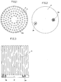
- Figure 1 is a top plan view of the apparatus according to the invention.
- Figure 2 is a vertical projection view by compared to Figure 1 with sectioned details of the mounting bars.
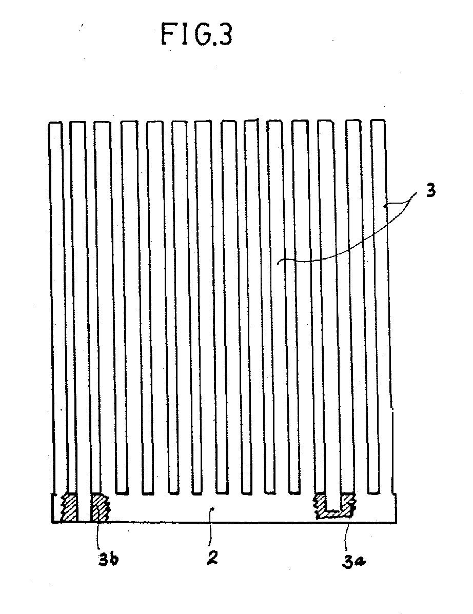
- Figure 3 is a 180 ° plan view of the figure 2.
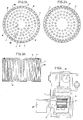
- Figure 1A is a top plan view of the apparatus, according to the invention, mounted in a combustion of an injection boiler.
- Figure 2A is equal to the previous one, installed in the combustion chamber of a sprinkler.
- FIG. 3A is a view in vertical projection of said appliance installed in a combustion chamber having air feeders.
- Figure 4 is a side detail of the installation of said devices in the general diagram of a boiler.
- the device consists of the circular base (2) in cast iron (preferably) with or without pressure means to the assembly and on which a battery of cylindrical bars (3), preferably cone-shaped and with equal diameter or section (d), distributed on rings concentric circulars where the separation or the radial (r) and horizontal (h) equidistance of these bars (3) between them, is equal to the diameter (d) thereof., although resulting partially misaligned in the radial projection and those of the inner ring having variable longitude.
- FIG. 1A An example of installation of the device in the combustion chamber (1) for an injection boiler (Fig. 1A) shows how the outer ring (4) of the bars (3) is included or engaged in the incisions (7) of said chamber (1).
- the bars (5) of the ring outside are distributed and spaced so that properly engage in said incisions (7) between streaks or ribs (8).
- the second ring (5) of bars (3) immediately concentric to the first is also distributed and spaced so that the bars (3) are supported tangentially against the interior plane (8a) of the ridges (8) of the combustion chamber (1).
- the central ring (6) frames a central zone (6A) free by where enters the burner flame by heating the bars (3) internal rings to facilitate this progressive overheating from the inside to the outside.
- the thermal accumulator (2) (3) is located having the base (2) against the bottom of the combustion chamber (1) in presenting the central space (6A) directly connected to the nozzle (11) of the burner (12).
Landscapes
- Engineering & Computer Science (AREA)
- Chemical & Material Sciences (AREA)
- Combustion & Propulsion (AREA)
- Mechanical Engineering (AREA)
- General Engineering & Computer Science (AREA)
- Physics & Mathematics (AREA)
- Thermal Sciences (AREA)
- Combustion Of Fluid Fuel (AREA)
- Spray-Type Burners (AREA)
Abstract
ACCUMULATEUR THERMIQUE ET ECONOMISEUR POUR CHAUDIÈRES DE
CHAUFFAGE DOMESTIQUE À GAS-OIL, constitué par un tambour
métallique en fonte, composé d'une base discoïde (2) et de
multiples barres (3) cylindriques de même longitude
distribuées dans plusieurs bagues concetriques (4-5)
désalignées radialement et qui sont logées dans la chambre
(1) de combustion des chaudières de chauffage à injection,
à arrosage, ou d'autres. Elles disposent d'un accès coaxial
(6A) libre et lorsque l'on les chauffe de l'intérieur vers
l'extérieur, elles économisent et accumulent la chaleur
qu'elles rayonneront dans un procédé continu, en réduisant
la consommation de combustible. Il est principalement
indiqué pour des chaudières domestiques de chauffage.
Description
L'invention concerne, selon le titre de celle-ci, un appareil accumulateur thermique incandescent pour tout genre de chaudières domestiques (ou industrielles), de préfèrence à gas-oil, soit par injection, arrosage ou analogue ayant la double mission et l'avantage de concentrer et d'accumuler les calories produites par le brûleur, en obtenant en même temps l'utilisation maximale du combustible.The invention relates, according to the title thereof, to a glowing thermal storage device for everything kind of domestic (or industrial) boilers, rather than diesel, either by injection, watering or analog having the dual mission and the advantage of focus and accumulate the calories produced by the burner, at the same time obtaining maximum use fuel.
L'invention est un appareil très simple qui accomplit un cycle très bien étudié de comportement pratique, en évitant l'affaiblissement ou le gaspillage des calories générées par le brûleur d'une chaudière de ce genre, en fonction du combustible qu'elle doit consommer pour les générer. Les calories sont directement absorbées et accumulées par l'appareil faisant l'objet de l'invention, en produisant en même temps l'utilisation maximale du combustible et un indice résiduaire très faible, aussi bien en ce qui concerne la matière non consommée (brûlée) qu'en ce qui concerne les fumées.The invention is a very simple apparatus which accomplishes a very well studied cycle of practical behavior, in avoiding the weakening or wasting of calories generated by the burner of a boiler of this kind, in depending on the fuel it should consume for generate. The calories are directly absorbed and accumulated by the device which is the subject of the invention, at the same time producing the maximum use of the combustible and a very low residual index, as well with regard to the material not consumed (burnt) that regarding fumes.
Etant donné la simplicité de l'appareil faisant l'objet de l'invention, susceptible d'être incorporé à n'importe quelle chaudière à gas-oil, en n'exigeant que l'ajustage des mesures aux dimensions de la chambre de combustion.Given the simplicity of the device making the subject of the invention, which can be incorporated into any diesel boiler, requiring only adjusting the measurements to the dimensions of the combustion.
Nous n'avons pas trouvé d'antécédents faisant une référence concrète à ce genre d'appareils.We did not find a history making a concrete reference to this kind of devices.
Nous pouvons, en effet, faire références à divers appareils et/ou brevets se rapportant à des économiseurs de combustible pour ce genre de chaudières, aux alimentateurs à rythmes ou débits d'approvisionnement contrôlé ou dosé pour économiser ou ne pas gaspiller du combustible.We can, indeed, make references to various devices and / or patents relating to economizers fuel for this kind of boilers, to the feeders at controlled or metered supply rates or flows to save or not waste fuel.
Particulièrement, ce genre d'appareils, se rapportent à un modèle déterminé de chaudières ou appareil de chauffage, car, soit ils sont conçus pour un type concret de chaudières existant sur le marché ou alors ils sortent de l'usine en l'incorporant.Especially, this kind of devices, relate to a specific model of boilers or heating because either they are designed for a concrete type of boilers existing on the market or they exit from the factory by incorporating it.
L'appareil faisant l'objet de l'invention, peut avantageusement, en principe, être installé dans n'importe quel type de chaudière, puisque les mesures peuvent s'adapter à n'importe quel modèle et, évidemment, elles peuvent aussi s'adapter directement à celles de nouvelle production à l'usine.The device which is the subject of the invention can advantageously, in principle, be installed in any what type of boiler, since the measurements can fit any model and obviously can also adapt directly to new ones production at the factory.
Un appareil simple aux caractéristiques de l'invention, permet un échauffement meilleur et plus rapide du fluide (de l'eau) du chauffage et une consommation de combustible plus faible, un coefficient résiduaire plus faible et une réduction considérable de la consommation (proportion logique mathématique lorsque l'on provoque le déclenchement plus rapide du thermostat régulateur de la température d'ambiance, celle-ci étant dépassée plus facilement).A simple device with the characteristics of the invention allows better and faster heating heating fluid (water) and consumption of lower fuel, a higher residual coefficient low and a considerable reduction in consumption (mathematical logical proportion when the faster activation of the regulator thermostat room temperature, this being exceeded more easily).
Dans le tableau d'essais, l'appareil de l'invention a
été expérimenté dans une chaudière ROCA type, VR-12. Dans
un logement de 80 mètres carrés, on a mis le régulateur de
la chaudière au point 1, l'eau du chauffage a dépassée 45°C
de température. La consommation moyenne par heure n'a pas
été supérieure à 0.60 litre, bien que l'on a laissé
refroidir, tous les jours, pendant quelques heures, l'eau
du chauffage et que l'on a mis ledit régulateur au point 2
jusqu'à ce que le brûleur faisant l'objet de l'invention se
chauffait.In the test table, the apparatus of the invention has
been tested in a typical ROCA boiler, VR-12. In
an accommodation of 80 square meters, we put the regulator of
the boiler at point 1, the heating water has exceeded 45 ° C
of temperature. Average consumption per hour has not
was more than 0.60 liter, although we left
cool the water every day for a few hours
heating and that we put the said regulator in
Dans un autre essai de l'appareil, on a mis le régulateur au point minimal pendant plusieurs jours, ce qui produisait une consommation de 0,39 litre par heure et l'eau s'est maintenue à une température non inférieure à 35°C, ce qui est suffisant pour maintenir una ambiance agréable dans le logement.In another test of the device, we put the regulator at minimum point for several days, which produced a consumption of 0.39 liters per hour and the water was kept at a temperature not lower than 35 ° C, which is enough to maintain an atmosphere pleasant in the accommodation.
Un autre avantage est le fait qu'avec ce système le prix des chaudière ne s'élève pas.Another advantage is the fact that with this system the price of the boiler does not rise.
Dans un autre aspect de l'invention, en chauffant, lors de l'allumage de la chaudière, un tube ou la paroi du four au moyen de l'électricité jusqu'à ce que le brûleur soit chaud, on réduit encore plus la contamination.In another aspect of the invention, by heating, when lighting the boiler, a tube or the wall of the oven using electricity until the burner either hot, contamination is further reduced.
Dans une étendue possible des applications de l'invention, on pourrait accoupler ce système aux moteurs à gas-oil et même à essence, ce serait une révolution qui augmenterait les ventes de véhicules et de machines à moteurs de combustion, et en plus, on reduirait la contamination et on protègerait l'environnement, puisque le combustible serait mieux brûlé.Within a possible range of applications of the invention, we could couple this system to motors diesel and even gasoline, it would be a revolution that increase sales of vehicles and machinery combustion engines, and in addition, we would reduce the contamination and we would protect the environment, since the fuel would be better burned.
On sait que les moteurs plus ils sont chauds moins ils consonmment. Les chemises et le combustible pourraient être chauffés extérieurement, au moyen de tubes et même au moyen de circuits; ceci peut encore être perfectionné.We know that the warmer the motors, the less they consequently. Liners and fuel could be heated externally, by means of tubes and even by means circuits; this can still be improved.
L'appareil faisant l'objet de l'invention, est une pièce simple métallique en fonte (de préférence) qui est muni d'une base discoïde d'une épaisseur d'environ un centimètre qui peut avoir des moyens de pression pour être ajustée à la chambre de combustion et à partir duquel sont projetées perpendiculairement de multiples tringles cylindriques massives, aussi, de préférence, en fonte, qui sont maintenues solidairement à la base et étant distribuées de manière équidistante horizontalement et radialement, mais désalignées dans cette dernière projection.The apparatus which is the subject of the invention is a single metal piece of cast iron (preferably) which is provided with a discoid base with a thickness of approximately one centimeter who can have leverage to be adjusted to the combustion chamber and from which are projected perpendicularly from multiple rods massive cylindrical, also, preferably, of cast iron, which are held together at the base and being evenly distributed horizontally and radially but misaligned in the latter projection.
Un autre détail de l'invention est le fait que le serrage des tringles à la base est fait, de préférence, par estampage ou encastrement en formant avec la base un corps unique.Another detail of the invention is the fact that the tightening of the rods at the base is preferably done by stamping or embedding by forming a body with the base unique.
Un autre détail est le fait que la longueur des tringles est approximativement la longueur de la chambre de combustion, en demeurant à courte distance du brûleur et pouvant varier sa longitude par rapport aux dimensions du brûleur, de manière que la flamme entre axialement entre les tringles centrales de l'accumulateur en s'étendant radialement au reste qui absorbe l'effluent thermique en l'accumulant et en le concentrant. L'induction permet de chauffer rapidement le fluide caloporteur (de l'eau) et sa capacité de concentration prolonge pendant plus de temps ladite irradiation ou ledit refroidissement de la chaudière.Another detail is the fact that the length of the rods is approximately the length of the combustion, staying a short distance from the burner and may vary its longitude from the dimensions of the burner, so that the flame enters axially between the central rods of the accumulator extending radially to the rest which absorbs the thermal effluent in accumulating it and concentrating it. Induction allows quickly heat the heat transfer fluid (water) and its ability to concentrate extends for longer said irradiation or said cooling of the boiler.
Un autre détail de l'invention est le fait que l'épaisseur ou section des barres est la même dans toutes celles-ci, et de préférence en forme de cône pour faciliter son démoulage.Another detail of the invention is the fact that the thickness or section of the bars is the same in all these, and preferably cone-shaped to facilitate its release.
Un autre détail de l'invention est le fait que la bague extérieure est dimensionnée et espacée circulairement entre les barres, de manière à pouvoir s'engager entre les stries de la chambre de combustion des chaudières à injection de ce genre.Another detail of the invention is the fact that the outer ring is dimensioned and circularly spaced between the bars, so as to be able to engage between the striations from the combustion chamber of the boilers injection like this.
Un autre détail est le fait que ladite bague extérieure est dimensionnée également et à la même fin que la précédente, tandis que la seconde bague extérieure, concentrique à la première, est dimensionnée et espacée circulairement pour prendre appui tangentiellement contre le chant horizontal des nervures de la chambre de combustion des chaudières à arrosage (égouttement).Another detail is the fact that said ring exterior is also dimensioned and for the same purpose as the previous one, while the second outer ring, concentric to the first, is dimensioned and spaced circularly to bear tangentially against the horizontal edge of the ribs in the combustion of sprinkler boilers (drip).
Un autre détail est le fait que l'équidistance de la séparation horizontale et radiale entre les barres est égale approximativement au diamètre de la section de celles-ci.Another detail is the fact that the equidistance of the horizontal and radial separation between the bars is approximately equal to the diameter of the section of these.
On apportera à la suite une idée plus large des caractéristiques essentielles de l'invention, lorsque l'on fera référence à la feuille de dessin adjointe à cette mémoire, où d'une façon un peu schématique et uniquement à mode d'exemple, on représente les détails préférés de l'invention.We will then bring a broader idea of essential characteristics of the invention, when one will refer to the drawing sheet attached to this memory, where in a somewhat schematic way and only to example mode we represent the preferred details of the invention.
Dans les dessins:In the drawings:
La figure 1, est une vue en plan supérieur de l'appareil, selon l'invention.Figure 1 is a top plan view of the apparatus according to the invention.
La figure 2, est une vue en projection verticale par rapport à la figure 1 avec des détails sectionnés du montage de barres.Figure 2 is a vertical projection view by compared to Figure 1 with sectioned details of the mounting bars.
La figure 3, est une vue en plan à 180° de la figure 2.Figure 3 is a 180 ° plan view of the figure 2.
La figure 1A, est une vue en plan supérieur de l'appareil, selon l'invention, monté dans une chambre de combustion d'une chaudière à injection.Figure 1A is a top plan view of the apparatus, according to the invention, mounted in a combustion of an injection boiler.
La figure 2A est égale à la précédente, installé dans la chambre de combustion d'une chaudière à arrosage.Figure 2A is equal to the previous one, installed in the combustion chamber of a sprinkler.
La figure 3A, est une vue en projection verticale dudit appareil installé dans une chambre de combustion ayant des alimentateurs d'air.FIG. 3A is a view in vertical projection of said appliance installed in a combustion chamber having air feeders.
La figure 4, est un détail latéral de l'installation desdits appareils dans le schéma général d'une chaudière.Figure 4 is a side detail of the installation of said devices in the general diagram of a boiler.
Selon la représentation des dessins, l'appareil, selon l'invention, est constitué de la base circulaire (2) en fonte (de préférence) avec ou sans moyens de pression pour le montage et sur lequel est disposée une batterie de barres cylindriques (3), de préférence en forme de cône et au diamètre ou section égal (d), distribuées sur des bagues circulaires concentriques où la séparation ou l'équidistance radiale (r) et horizontale (h) de ces barres (3) entre elles, est égale au diamètre (d) de celles-ci., bien qu'en résultant partiellement désalignées dans la projection radiale et celles de la bague intérieure ayant une longitude variable.According to the representation of the drawings, the device, according the invention consists of the circular base (2) in cast iron (preferably) with or without pressure means to the assembly and on which a battery of cylindrical bars (3), preferably cone-shaped and with equal diameter or section (d), distributed on rings concentric circulars where the separation or the radial (r) and horizontal (h) equidistance of these bars (3) between them, is equal to the diameter (d) thereof., although resulting partially misaligned in the radial projection and those of the inner ring having variable longitude.
Dans la figure 2, on représente un exemple de montage préféré des barres (3) sur la base (2), soit par encastrement (3b) soit par estampage (3a), en formant solidairement un corps avec la base (2).In Figure 2, an example of assembly is shown preferred bars (3) on the base (2), either by embedding (3b) or by stamping (3a), forming integrally a body with the base (2).
Un exemple d'installation de l'appareil dans la chambre (1) de combustion pour une chaudière à injection (Fig. 1A) montre comment la bague extérieure (4) des barres (3) est comprise ou engagée dans les incisions (7) de ladite chambre (1). A cet effet, les barres (5) de la bague extérieure sont distribuées et espacées de façon à s'engager convenablement dans lesdites incisions (7) entre les stries ou nervures (8).An example of installation of the device in the combustion chamber (1) for an injection boiler (Fig. 1A) shows how the outer ring (4) of the bars (3) is included or engaged in the incisions (7) of said chamber (1). For this purpose, the bars (5) of the ring outside are distributed and spaced so that properly engage in said incisions (7) between streaks or ribs (8).
La seconde bague (5) de barres (3) immédiatement concentrique à la première est également distribuée et espacée de façon que les barres (3) pennent appui tangentiellement contre le plan intérieur (8a) des stries (8) de la chambre de combustion (1).The second ring (5) of bars (3) immediately concentric to the first is also distributed and spaced so that the bars (3) are supported tangentially against the interior plane (8a) of the ridges (8) of the combustion chamber (1).
Selon l'on peut apprécier principalement dans les figures 1A et 2A entre la bague extérieure (4) et intérieure (6) les barres (3) sont désalignées radialement.According to one can mainly appreciate in Figures 1A and 2A between the outer ring (4) and interior (6) the bars (3) are radially misaligned.
La bague centrale (6) encadre une zone centrale (6A) libre par où entre la flamme du brûleur en chauffant les barres (3) des bagues internes pour faciliter ce surchauffage progressif de l'interieur vers l'exterieur.The central ring (6) frames a central zone (6A) free by where enters the burner flame by heating the bars (3) internal rings to facilitate this progressive overheating from the inside to the outside.
L'accumulateur thermique des figures 1, 2 et 3 dans une chambre de combustion (9) (Fig. 3A) d'une chaudière par arrosage, est placé avec les barres (3) vers le fond, de manière qu'elles soient parallèles aux lumières (9a) de ventilation ou entrées d'air.The thermal accumulator of Figures 1, 2 and 3 in a combustion chamber (9) (Fig. 3A) of a boiler by watering, is placed with the bars (3) towards the bottom, so that they are parallel to the lights (9a) of ventilation or air inlets.
Cette aménagement dans la chaudière (10) par injection est représenté dans la figure 4.This arrangement in the boiler (10) by injection is shown in figure 4.
L'accumulateur thermique (2) (3) est situé en ayant la base (2) contre le fond de la chambre de combustion (1) en présentant l'espace central (6A) directement embouché dans la buse (11) du brûleur (12).The thermal accumulator (2) (3) is located having the base (2) against the bottom of the combustion chamber (1) in presenting the central space (6A) directly connected to the nozzle (11) of the burner (12).
Une fois décrite convenablement la nature de l'invention, on fait remarquer aux effets appropriés, que celui-ci ne se limite pas aux détails exacts de cette exposition, mais au contraire, on y introduira les modifications que l'on considère opportunes, sans altérer ses caractéristiques essentielles, que l'on revendique à la suite.Once properly described the nature of the invention, it is pointed out with appropriate effects, that this is not limited to the exact details of this exhibition, but on the contrary, we will introduce modifications that we consider appropriate, without altering its essential characteristics, which we claim to after.
Claims (7)
Applications Claiming Priority (2)
| Application Number | Priority Date | Filing Date | Title |
|---|---|---|---|
| ES9602753 | 1996-12-27 | ||
| ES009602753A ES2138515B1 (en) | 1996-12-27 | 1996-12-27 | THERMAL ACCUMULATOR AND ECONOMIZER FOR DOMESTIC HEATING BOILERS GASOIL. |
Publications (2)
| Publication Number | Publication Date |
|---|---|
| EP0851181A2 true EP0851181A2 (en) | 1998-07-01 |
| EP0851181A3 EP0851181A3 (en) | 1999-11-10 |
Family
ID=8297170
Family Applications (1)
| Application Number | Title | Priority Date | Filing Date |
|---|---|---|---|
| EP97500224A Withdrawn EP0851181A3 (en) | 1996-12-27 | 1997-12-23 | Heat accumulator and economiser for domestical gas-fired boilers |
Country Status (2)
| Country | Link |
|---|---|
| EP (1) | EP0851181A3 (en) |
| ES (1) | ES2138515B1 (en) |
Cited By (2)
| Publication number | Priority date | Publication date | Assignee | Title |
|---|---|---|---|---|
| CN103245056A (en) * | 2013-04-18 | 2013-08-14 | 苏州艾克玛能源科技有限公司 | Stack thermal collector |
| CN107002996A (en) * | 2014-11-26 | 2017-08-01 | 伊拉里奥·布兰科戈麦斯 | Radiant heat chambers for boilers |
Family Cites Families (4)
| Publication number | Priority date | Publication date | Assignee | Title |
|---|---|---|---|---|
| DE1751564A1 (en) * | 1968-03-29 | 1971-07-08 | Manfred Walz Fa | Glow body |
| EP0028830A1 (en) * | 1979-11-12 | 1981-05-20 | Huber, Markus Gerätebau | Central-heating boiler with infinitely adjustable heating surfaces in the shape of a spiral and cleanable from the outside |
| HU186793B (en) * | 1981-11-16 | 1985-09-30 | Laszlo Toth | Local heating equipment |
| SE444854B (en) * | 1984-07-31 | 1986-05-12 | Smart & Simple Energy Systems | MARKVERMEACKUMULATOR |
-
1996
- 1996-12-27 ES ES009602753A patent/ES2138515B1/en not_active Expired - Fee Related
-
1997
- 1997-12-23 EP EP97500224A patent/EP0851181A3/en not_active Withdrawn
Cited By (3)
| Publication number | Priority date | Publication date | Assignee | Title |
|---|---|---|---|---|
| CN103245056A (en) * | 2013-04-18 | 2013-08-14 | 苏州艾克玛能源科技有限公司 | Stack thermal collector |
| CN103245056B (en) * | 2013-04-18 | 2016-05-18 | 苏州艾克玛能源科技有限公司 | Stack heat collector |
| CN107002996A (en) * | 2014-11-26 | 2017-08-01 | 伊拉里奥·布兰科戈麦斯 | Radiant heat chambers for boilers |
Also Published As
| Publication number | Publication date |
|---|---|
| EP0851181A3 (en) | 1999-11-10 |
| ES2138515B1 (en) | 2000-08-16 |
| ES2138515A1 (en) | 2000-01-01 |
Similar Documents
| Publication | Publication Date | Title |
|---|---|---|
| FR2913105A1 (en) | Condensation heat exchanger for fuel or gas boiler, has light whose circumferential sector is passed over and traversed by gas generated by burner and remaining sectors are passed over and traversed by gas generated by another burner | |
| EP2396607A2 (en) | Solar collector, and power-generating plant including such solar collectors | |
| FR2948991A1 (en) | MODULAR MULTI-ENERGY THERMODYNAMIC DEVICE | |
| CH639187A5 (en) | BOILER, ESPECIALLY FOR A HEATING SYSTEM. | |
| FR2576404A1 (en) | HEAT EXCHANGER AND APPLICATION TO A HEATING APPARATUS OF A FLUID, ESPECIALLY HEAT HOT WATER ACCUMULATOR | |
| CN110657590A (en) | Thermoelectric power generation furnace | |
| EP3274637B1 (en) | Boiler and door to said boiler | |
| FR2999830A1 (en) | ELEMENT FOR THE TREATMENT OF IMPROVED SOLAR RADIATION AND A SOLAR FOLLOWER AND A SOLAR POWER PLANT EQUIPPED WITH SUCH ELEMENT | |
| BE1026742B1 (en) | Method for transferring condensation energy from the steam of cogeneration fumes | |
| EP2405209A1 (en) | Air-intake and mixing device for a heat pump | |
| BE1017517A6 (en) | Condensation energy recuperation self-portrait chimney e.g. heat exchanger, for e.g. pan, has turbulator removably placed in core of drum to whirl smoke, and ring gear placed in envelop under sleeve of water inlet and above water outlet | |
| EP2406557B1 (en) | Solar equipment | |
| FR2975170B1 (en) | CONDENSER AND APPARATUS EQUIPPED WITH SUCH CONDENSER. | |
| FR2938318A1 (en) | IMMERSION TUBE HEATING SYSTEM WITH LATENT HEAT RECOVERY | |
| FR2459948A1 (en) | Solar water heater with pyramidal reservoir - has convection currents established under influence of solar radiation causing hottest water to collect at apex (PT 12.12.80) | |
| EP1147340A1 (en) | Pot burner | |
| EP0127881B1 (en) | Hot water generator, in particular a central heating boiler, for solid fuel, especially for burning logs of wood | |
| KR200400896Y1 (en) | The heating system | |
| WO1992019920A1 (en) | Boiler for central heating and/or sanitary hot water production, burner for gas fuel, and installation for central heating and sanitary hot water production using said boiler | |
| RU2002126023A (en) | ENERGY INSTALLATION | |
| EP2275744A1 (en) | Heavy-duty stove with built-in boiler | |
| CA2499143A1 (en) | Regulating heat exchange and cooling method and system for monitoring and controlling the temperatures of walls subjected to high temperatures | |
| FR2609152A1 (en) | Removable furnace body, burning poor-grade (lean) fuel, for an industrial generator | |
| FR2505461A1 (en) | Heat recuperator for hot water boiler - has water coil around exhaust gas duct with insulation packing | |
| BE895560A (en) | Heat recuperator for wood burning stove - encloses stove, with space for liquid circulating coil wound round flue pipe |
Legal Events
| Date | Code | Title | Description |
|---|---|---|---|
| PUAI | Public reference made under article 153(3) epc to a published international application that has entered the european phase |
Free format text: ORIGINAL CODE: 0009012 |
|
| AK | Designated contracting states |
Kind code of ref document: A2 Designated state(s): AT BE CH DE DK FR GB GR IE IT LI LU MC NL PT SE |
|
| AX | Request for extension of the european patent |
Free format text: AL;LT;LV;MK;RO;SI |
|
| 17P | Request for examination filed |
Effective date: 19980618 |
|
| PUAL | Search report despatched |
Free format text: ORIGINAL CODE: 0009013 |
|
| AK | Designated contracting states |
Kind code of ref document: A3 Designated state(s): AT BE CH DE DK ES FI FR GB GR IE IT LI LU MC NL PT SE |
|
| AX | Request for extension of the european patent |
Free format text: AL;LT;LV;MK;RO;SI |
|
| AKX | Designation fees paid |
Free format text: AT BE CH DE DK FR GB GR IE IT LI LU MC NL PT SE |
|
| GRAG | Despatch of communication of intention to grant |
Free format text: ORIGINAL CODE: EPIDOS AGRA |
|
| 17Q | First examination report despatched |
Effective date: 20010319 |
|
| GRAG | Despatch of communication of intention to grant |
Free format text: ORIGINAL CODE: EPIDOS AGRA |
|
| GRAH | Despatch of communication of intention to grant a patent |
Free format text: ORIGINAL CODE: EPIDOS IGRA |
|
| STAA | Information on the status of an ep patent application or granted ep patent |
Free format text: STATUS: THE APPLICATION IS DEEMED TO BE WITHDRAWN |
|
| 18D | Application deemed to be withdrawn |
Effective date: 20011009 |