EP2406557B1 - Solareinrichtung - Google Patents
Solareinrichtung Download PDFInfo
- Publication number
- EP2406557B1 EP2406557B1 EP10710904.3A EP10710904A EP2406557B1 EP 2406557 B1 EP2406557 B1 EP 2406557B1 EP 10710904 A EP10710904 A EP 10710904A EP 2406557 B1 EP2406557 B1 EP 2406557B1
- Authority
- EP
- European Patent Office
- Prior art keywords
- container
- heat
- energy
- containers
- installation according
- Prior art date
- Legal status (The legal status is an assumption and is not a legal conclusion. Google has not performed a legal analysis and makes no representation as to the accuracy of the status listed.)
- Not-in-force
Links
Images



Classifications
-
- F—MECHANICAL ENGINEERING; LIGHTING; HEATING; WEAPONS; BLASTING
- F24—HEATING; RANGES; VENTILATING
- F24S—SOLAR HEAT COLLECTORS; SOLAR HEAT SYSTEMS
- F24S60/00—Arrangements for storing heat collected by solar heat collectors
- F24S60/10—Arrangements for storing heat collected by solar heat collectors using latent heat
-
- F—MECHANICAL ENGINEERING; LIGHTING; HEATING; WEAPONS; BLASTING
- F24—HEATING; RANGES; VENTILATING
- F24S—SOLAR HEAT COLLECTORS; SOLAR HEAT SYSTEMS
- F24S20/00—Solar heat collectors specially adapted for particular uses or environments
- F24S20/20—Solar heat collectors for receiving concentrated solar energy, e.g. receivers for solar power plants
- F24S2020/23—Solar heat collectors for receiving concentrated solar energy, e.g. receivers for solar power plants movable or adjustable
-
- Y—GENERAL TAGGING OF NEW TECHNOLOGICAL DEVELOPMENTS; GENERAL TAGGING OF CROSS-SECTIONAL TECHNOLOGIES SPANNING OVER SEVERAL SECTIONS OF THE IPC; TECHNICAL SUBJECTS COVERED BY FORMER USPC CROSS-REFERENCE ART COLLECTIONS [XRACs] AND DIGESTS
- Y02—TECHNOLOGIES OR APPLICATIONS FOR MITIGATION OR ADAPTATION AGAINST CLIMATE CHANGE
- Y02B—CLIMATE CHANGE MITIGATION TECHNOLOGIES RELATED TO BUILDINGS, e.g. HOUSING, HOUSE APPLIANCES OR RELATED END-USER APPLICATIONS
- Y02B10/00—Integration of renewable energy sources in buildings
- Y02B10/20—Solar thermal
-
- Y—GENERAL TAGGING OF NEW TECHNOLOGICAL DEVELOPMENTS; GENERAL TAGGING OF CROSS-SECTIONAL TECHNOLOGIES SPANNING OVER SEVERAL SECTIONS OF THE IPC; TECHNICAL SUBJECTS COVERED BY FORMER USPC CROSS-REFERENCE ART COLLECTIONS [XRACs] AND DIGESTS
- Y02—TECHNOLOGIES OR APPLICATIONS FOR MITIGATION OR ADAPTATION AGAINST CLIMATE CHANGE
- Y02E—REDUCTION OF GREENHOUSE GAS [GHG] EMISSIONS, RELATED TO ENERGY GENERATION, TRANSMISSION OR DISTRIBUTION
- Y02E10/00—Energy generation through renewable energy sources
- Y02E10/40—Solar thermal energy, e.g. solar towers
-
- Y—GENERAL TAGGING OF NEW TECHNOLOGICAL DEVELOPMENTS; GENERAL TAGGING OF CROSS-SECTIONAL TECHNOLOGIES SPANNING OVER SEVERAL SECTIONS OF THE IPC; TECHNICAL SUBJECTS COVERED BY FORMER USPC CROSS-REFERENCE ART COLLECTIONS [XRACs] AND DIGESTS
- Y02—TECHNOLOGIES OR APPLICATIONS FOR MITIGATION OR ADAPTATION AGAINST CLIMATE CHANGE
- Y02E—REDUCTION OF GREENHOUSE GAS [GHG] EMISSIONS, RELATED TO ENERGY GENERATION, TRANSMISSION OR DISTRIBUTION
- Y02E10/00—Energy generation through renewable energy sources
- Y02E10/40—Solar thermal energy, e.g. solar towers
- Y02E10/46—Conversion of thermal power into mechanical power, e.g. Rankine, Stirling or solar thermal engines
Definitions
- the present invention relates to the storage of energy and the production of electrical energy from solar energy.
- the plant is planned with a high power, which involves many sensors over a large area, so that electricity production remains geographically localized, which can cause problems transmission and limits the use of solar energy in the territory.
- US 4,205,656 discloses a solar energy storage system comprising spherical containers containing a state change material.
- Requirement GB 2,447,864 teaches to transport modules comprising a material for change of state from a heating location, constituted for example by a heat engine, to a place of use, for example dwellings.
- the invention aims to propose a new solar installation that is relatively simple to implement, satisfactory performance, and compatible with a large-scale implementation.
- the subject of the invention is a solar installation, according to claim 1.
- the heating and heat recovery zones are advantageously spaced from each other, in order to generate the least possible shade on the sensor.
- the recovery zone can for example be placed behind the sensor.
- the above material advantageously has a heat capacity greater than 0.5 kJ k -1 kg -1 and a latent heat greater than 200 kJ kg -1 .
- the production of electricity can be spread over a whole day from the thermal energy stored at high temperature during the day of sunshine, in particular as latent heat.
- thermodynamic converter associated with the installation as well as the size of the electrical lines of connection to the distribution network, which is particularly advantageous for the sites. isolated production, away from the places of electricity consumption.
- thermodynamic converter so as to enable it to produce at a specific time of the day, especially at night or at the peak of power consumption, the desired electrical power, of independently of the size and power of the solar collector.
- the low temperature thermal energy resulting from the cooling of the thermodynamic converter can be used locally, if necessary, for example for the heating of sanitary water or dwellings.
- the invention makes it possible to distribute several installations on the electrical network rather than concentrating the sensors in one and the same place, which is the case for conventional solar power plants that include energy storage with heat transfer fluids within a complex circuit. .
- the container is rotated on itself.
- the container can pass through the solar collector.
- the container is annular in shape, which facilitates the setting in motion and scrolling closed loop between the heating and heat recovery zones.
- the installation may comprise several containers, integral with each other, for example arranged side-by-side, end-to-end or interlaced, or interconnected by links or joints or otherwise.
- the solid / liquid state change material may comprise aluminum, in particular essentially consisting of aluminum.
- aluminum can allow non-polluting and recyclable storage, with readily available materials.
- thermodynamic converter may comprise at least one Stirling engine or the like or a steam turbine, among other possibilities.
- the heating zone may be located substantially at the focus of a parabolic mirror, whose opening diameter is for example between 2 and 10 m.
- a parabolic mirror whose opening diameter is for example between 2 and 10 m.
- several mirrors for example planar, spherical or parabolic, can focus the light to the heating zone.
- the installation may include an auxiliary heat generator, for heating the container (s) or the thermodynamic converter.
- an auxiliary heat generator for heating the container (s) or the thermodynamic converter.
- the production of electrical energy can be provided by the auxiliary heat generator, by heating the container (s) and returning the heat to the thermodynamic converter or alternatively by directly heating the thermodynamic converter.
- the auxiliary heat generator can use any source of fossil energy. The presence of a burner can thus allow to prolong the production of energy by burning a fuel, without resorting to a generator or a conventional thermal power station.
- the container may be integral with a sensor orientation system.
- the invention can, thanks to temperature measurements, to know the energy stored by the installation, and an information transmission system can be used to report early enough to a manager of an electrical network to which is connected the installation, the need or not to start a possible external backup source or the aforementioned auxiliary heat generator.
- the manager of the electricity network can also take into account solar forecasting on a 24-hour scale, for decision-making.
- heat can be transmitted to the container directly by exposing the container to light or alternatively via any element heated by light.
- the container can move, at least for part of its path, within a thermally insulating envelope, especially between the heating and recovery zones.
- ring-shaped container formed by several sections of curved tubes interconnected by plugs, each section containing the aforementioned material.
- these containers may each be formed from several sections of curved tubes connected together by plugs, and the plugs may ensure the connection between them, not only of two consecutive sections of tubes.
- Different compartments of the same annular container, formed by said sections may each contain the material, without communication between the compartments.
- these containers can be divided into two groups that rotate in the opposite direction, which makes it easier to homogenize the temperature of the containers.
- the containers of the bundle may be arranged around an annular internal frame, which may be solid and accumulate thermal energy, being advantageously arranged around the same thermally insulating envelope as the container or containers.
- the container or containers may for example roll on this internal frame, the bearings being for example arranged such that a relative rotation of a group of containers relative to this internal frame causes a rotation in opposite direction of the other group of containers.
- the internal frame can be interrupted especially in the heating zone, so as not to impede the transmission of light to the focus to the container or containers and can also be interrupted, if necessary, in the recovery zone.
- the container or containers is preferably used a material resistant to at least 200 ° C, better 700 ° C, more preferably 800 ° C.
- the monolithic container can be made, if necessary, with a solid section to accumulate the sensible heat.
- the invention further relates, in another aspect, to a method of converting solar energy into mechanical energy according to claim 9.
- the container forms a loop, being annular in shape, and rotated on itself.
- the container can be moved continuously relative to the heating zone so as to standardize the temperature of the container and the material therein.
- the container or containers may be temporarily immobilized relative to the heat recovery zone, which allows for example a clamping of the container or containers against a heat transfer surface for the time necessary for heat transfer. Then, the container (s) can be moved a certain distance to bring a new portion of the container (s) or other containers into the heat recovery zone.
- the heat recovery zone may comprise one or more jaws and a means for moving these jaws relative to the containers, the jaws being actuated to bring the container or containers in contact with a heat transfer surface, to facilitate heat transfer during the restitution of the thermal energy accumulated by the container or containers.
- the jaws can be actuated to spread the transfer surface of the container or containers when the displacement of the latter is necessary.
- the container or the thermodynamic converter may be subjected to the heat produced by an auxiliary heat generator, in the absence or in case of insufficient sun, as mentioned above.
- a solar installation comprising a thermal energy storage system comprising an element capable of accumulating sensible heat and / or latent heat, displaced in a closed loop relative to a heating zone, at least partially within a heating zone.
- a thermally insulating enclosure comprising an element capable of accumulating sensible heat and / or latent heat, displaced in a closed loop relative to a heating zone, at least partially within a heating zone.
- This installation may include a heat recovery zone.
- This installation may comprise several containers as defined above, for example of annular or chain form.
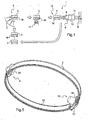
- FIG. 1 It is shown schematically in the figure 1 a first example of installation 1 made according to the invention for the storage of solar energy and the production of electrical energy from the stored thermal energy.
- the installation comprises at least one container 2 containing a solid / liquid state change material M, for example aluminum, the container / material assembly being able to constitute a mobile module.
- a solid / liquid state change material M for example aluminum
- the installation 1 also comprises at least one solar collector 3 making it possible to raise the temperature of the material M contained in at least one container 2 when the latter is in a heating zone 4, which coincides, for example, substantially with the focus of a parabolic mirror.
- the installation 1 comprises, in a recovery zone 12, a recovery system 8 of the thermal energy stored by the material M of at least one container 2, this recovery system 8 being associated with a thermodynamic converter comprising, for example an exchanger 9 and a Stirling engine 6 coupled to an electric generator 11 connected to an electrical network R.
- a thermodynamic converter comprising, for example an exchanger 9 and a Stirling engine 6 coupled to an electric generator 11 connected to an electrical network R.
- the installation comprises several containers 2 each containing a certain amount of the material M, and conveying means for moving the containers 2 between the heating zone 4 and the recovery zone 12.
- the containers 2 can be linked together or independent.
- a single container 2 or more side-by-side containers may also be used, as exemplified below.
- the conveying means may transport the container or containers 2 from the heating zone 4 to the recovery zone 12, then from the recovery zone 12 to the heating zone 4, possibly passing through one or more storage zones. intermediate.
- the energy storage can be done by transporting the containers of a low temperature storage area where the modules can be stored waiting for use to the heating zone or zones. Once heated and the fusible material M contained inside melted, a module can be stored in a heat-insulated hot storage area, waiting for the destocking of energy, which can be done by transporting the modules of the zone hot storage to the thermal energy recovery zone (s).
- the installation 1 may include an auxiliary heat generator 13 for heating the material M or the thermodynamic converter in the absence of sun or in case of insufficient sunlight, so as to be able to use as a means electricity production recovery system 8 and thus avoid the need for an additional electricity generator.
- the heat generator Annex 13 may include one or more burners of fossil energy.
- the container or containers 2 containing the material M may be in the form of modules of all shapes suitable for their conveying and the collection of light energy and the return of the thermal energy.
- a container 2 comprises for example a steel casing.
- the shape of the containers may be spherical, cylindrical, toroidal, parallelepipedic or other.
- the envelope of a container can be made to resist the liquid aluminum and the impact of the light at the focus of the sensor.
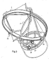
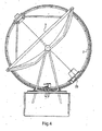
- FIG. 2 An installation 1 according to an alternative embodiment of the invention, comprising a container 2 of annular shape about an axis which is for example, as illustrated, perpendicular to an axis of symmetry of the sensor 3.
- the container 2 may be guided in displacement by a guide structure 20 secured to a support structure 21 of a parabolic mirror of the sensor.
- a motor 23 may be provided to rotate the container 2 on itself.
- the sizing of the container 2 can be chosen so as to allow to accumulate the energy of a day of sunshine, for example to restore it during the night.
- the container 2 can pass through the mirror of the sensor 3 through openings 25, as can be seen in FIG. figure 2 .
- the sensor 3 is advantageously supported by an orientation system to enable it to follow the sun, equipped with engines 26 and 27.
- the container 2 contains the material M to change solid / liquid state and a given portion of the container 2 can be moved between a heating zone 4 and a return zone 12, thanks to the engine 23.
- the container 2 is for example rotated continuously during storage, and in increments during playback.
- the container 2 can circulate inside a thermally insulated envelope 30, of generally annular shape, which can be integral with a light energy collection system 35 and a system 40 for the return of thermal energy. stored.
- This envelope 30 may be of multilayer structure, for example with a gap between two adjacent layers.
- the collection system 35 may comprise, as seen in FIG. figure 6 an opening 42 intended to receive the concentrated light radiation at the focus of the parabolic mirror and transmit by conduction and / or radiation the heat to the container 2 and the material contained therein, in particular at the portion of the container 2 passing through the collection system 35.
- the container 2 may possibly be exposed directly to the light at the focus of the sensor.
- the recovery system 40 may include any heat exchanger adapted to recover the thermal energy stored by the material M.
- the recovery system 40 may optionally include a burner to allow the production of energy in the absence of sun and depletion of thermal energy accumulated in the container.
- the variant illustrated in Figures 7 to 10 comprises several containers 2 joined in annular bundle, with the beam a radially inwardly open section.
- Each of the ring-shaped containers for example toric, may be formed by several sections of curved tubes assembled end-to-end to form a torus. The assembling of the sections can be done by plugs which can thus compartmentalize the torus, each compartment can be filled with the material M, for example aluminum.
- the plugs used to assemble the sections can also hold the annular containers together to form the bundle. It may be advantageous to separate the beam into two groups of containers, for example two groups 120a and 120b of five containers, as illustrated in FIG. figure 8 , each corresponding to one half of the beam, these two groups being able to rotate in opposite directions.
- the beam can be supported by an internal frame 95 that can be seen in particular on the figure 10 , on which the containers can roll, the armature 95 being contained in the thermally insulating envelope 30 and being interrupted at the heating zone and the thermal recovery zone.
- the bearings used to guide containers into rotation on the inner armature can be configured so that the rotation in one direction of one of the groups of the beam is accompanied by the rotation in the opposite direction of the other group of the beam.
- the internal armature 95 is connected in its interrupted part by a part 96 which defines the opening of the heating zone.
- the light can be focused at the focus of the sensor inside the beam, the containers being for example exposed directly to the light.
- the heat energy recovery system may comprise a conduit 50 traversed by a heat transfer fluid extending around the bundle of containers 2.
- the jaws 99 press the containers 2 against the transfer surface 104 during the restitution phase, and the jaws 99 are actuated so as to release the containers 2 when it is necessary to move the latter to bring a new portion or other containers in contact with the heat transfer surface 104.
- the two groups 120a and 120b of containers 2 can be moved in opposite directions continuously in order to accumulate the thermal energy and during the phase of restitution of thermal energy, the groups of containers 120a and 120b can be moved in increments, according to an intermittent motion with immobilization during the heat recovery phase.
- the recovery zone may be provided with fins 130 subjected to the heat generated by combustion of one or more burners of the auxiliary heat generator.
- the conduit 50 may contain, for example, gas from a Stirling engine or steam supplying a steam turbine and may be associated with a single Stirling engine or a single steam turbine.
- several heat recovery zones may be associated with the same thermodynamic converter.
- a steam turbine can be supplied with steam by several installations each comprising the sensor, the energy storage system, and a heat recovery zone.
- thermodynamic converter comprising a Stirling engine driving an electric generator.
- the heating zone is defined by the focus of a parabolic mirror solar collector.
- thermodynamic converter A cold source at 60 ° C (convection ambient air) is used for the thermodynamic converter
- the electrical power will be 3kW continuously day and night.
- the efficiency of the electrical restitution of the storage of 41.5% ie a solar / electrical efficiency including storage of 33.2%, that is to say close to 3 times that of photovoltaic cells but with in addition to the hot water at 60 ° C usable and with a very large storage capacity, thus decoupling hourly production / hours of use.
- the energy saving by fossil energy is direct by burner without additional installation.
- the solar / electrical efficiency including storage is 8.4%.
- thermodynamic converters can be used.
- the energy recovery zone may be located elsewhere than at the rear of the sensor.
Landscapes
- Engineering & Computer Science (AREA)
- Physics & Mathematics (AREA)
- Life Sciences & Earth Sciences (AREA)
- Sustainable Development (AREA)
- Sustainable Energy (AREA)
- Thermal Sciences (AREA)
- Chemical & Material Sciences (AREA)
- Combustion & Propulsion (AREA)
- Mechanical Engineering (AREA)
- General Engineering & Computer Science (AREA)
- Photovoltaic Devices (AREA)
- Engine Equipment That Uses Special Cycles (AREA)
Claims (11)
- Solareinrichtung (1) zur Erzeugung mechanischer und/oder elektrischer Energie, mit
einem thermodynamischen Konverter,
wenigstens einem Sonnenkollektor (3) zum Weitergeben von Sonnenlicht auf eine Erwärmungszone (4),
wenigstens einer Zone zur thermischen Rückgewinnung (12),
wenigstens einem ringförmigen Behälter (2), der ein Material (M) enthält, das zum Ansammeln wahrnehmbarer Wärme sowie vorzugsweise für Änderungen des Zustands fest/flüssig geeignet ist
wenigstens einem Antriebssystem des Behälters, um wenigstens einen Teil desselben relativ zu der Erwärmungszone (4) und der Zone thermischer Rückgewinnung (12) zu verschieben,
wobei der Behälter (2) selbst zur Rotation angetrieben wird. - Einrichtung nach Anspruch 1, wobei das Material seine Zustand fest/flüssig ändert und Aluminium enthält, insbesondere im Wesentlichen aus Aluminium besteht.
- Einrichtung nach einem der vorstehenden Ansprüche, wobei der thermodynamische Konverter ein Stirling-Motor ist.
- Einrichtung nach einem der vorstehenden Ansprüche, wobei die Erwärmungszone im Wesentlichen im Brennpunkt eines Parabolspiegels angeordnet ist.
- Einrichtung nach einem der vorstehenden Ansprüche, mit einem Wärmegeneratoranbau zum Erwärmen des Behälters (2), der die in dem Behälter gespeicherte thermische Energie rückgewinnt.
- Einrichtung nach einem der vorstehenden Ansprüche, wobei der Behälter (2) den Kollektor (3) durchdringt.
- Einrichtung nach einem der vorstehenden Ansprüche, wobei der Behälter (2) fest mit einem Orientierungssystem des Kollektors verbunden ist.
- Einrichtung nach einem der Ansprüche 1 bis 7, wobei der oder die Behälter wenigstens über einen Teil seiner Erstreckung im Inneren einer thermisch isolierenden Umhüllung angeordnet ist.
- Verfahren zur Konversion von Sonnenenergie in mechanische Energie, das eine Solareinrichtung gemäß einem der vorstehenden Ansprüche einsetzt, wobei in dem Verfahren Schritte ausgeführt werden, in denen
wenigstens ein Teil wenigstens eines Behälters (2), der ein Material (M) enthält, das zum Sammeln von wahrnehmbarer Wärme und vorzugsweise zur Änderung des Zustands fest/flüssig geeignet ist, einer Wärme ausgesetzt wird, die durch die Konzentration von Sonnenenergie in einer Erwärmungszone (4) erzeugt wurde,
der so erwärmte Teil des Behälters relativ zu der Erwärmungszone verschoben wird, insbesondere in Richtung einer Zone zur thermischen Rückgewinnung (12),
aus der thermischen Energie, die durch das Material gesammelt und in der Zone thermischer Rückgewinnung wiedergewonnen wurde, mechanische Energie erzeugt wird. - Verfahren nach dem vorstehenden Anspruch, wobei der Behälter während des Energiesammelns kontinuierlich und während der Rückgewinnung intermittierend verschoben wird.
- Verfahren nach einem der Ansprüche 9 und 10, wobei zwei Gruppen (120a, 120b) von Behältern in umgekehrter Richtung verschoben werden, so dass die Temperatur des Materials (M) in ihrem Inneren vereinheitlicht wird.
Applications Claiming Priority (2)
| Application Number | Priority Date | Filing Date | Title |
|---|---|---|---|
| FR0901207A FR2943121B1 (fr) | 2009-03-13 | 2009-03-13 | Installation solaire |
| PCT/IB2010/051084 WO2010103496A1 (fr) | 2009-03-13 | 2010-03-12 | Installation solaire |
Publications (2)
| Publication Number | Publication Date |
|---|---|
| EP2406557A1 EP2406557A1 (de) | 2012-01-18 |
| EP2406557B1 true EP2406557B1 (de) | 2014-12-03 |
Family
ID=41343493
Family Applications (1)
| Application Number | Title | Priority Date | Filing Date |
|---|---|---|---|
| EP10710904.3A Not-in-force EP2406557B1 (de) | 2009-03-13 | 2010-03-12 | Solareinrichtung |
Country Status (4)
| Country | Link |
|---|---|
| EP (1) | EP2406557B1 (de) |
| ES (1) | ES2531273T3 (de) |
| FR (1) | FR2943121B1 (de) |
| WO (1) | WO2010103496A1 (de) |
Families Citing this family (2)
| Publication number | Priority date | Publication date | Assignee | Title |
|---|---|---|---|---|
| DE102014105617A1 (de) * | 2014-04-22 | 2015-10-22 | Jochen Benz | Solarthermiesystem sowie Betriebsverfahren eines Solarthermiesystems |
| GB202012758D0 (en) * | 2020-08-14 | 2020-09-30 | Odqa Renewable Energy Tech Limited | Solar flux device |
Family Cites Families (7)
| Publication number | Priority date | Publication date | Assignee | Title |
|---|---|---|---|---|
| US4676068A (en) * | 1972-05-12 | 1987-06-30 | Funk Harald F | System for solar energy collection and recovery |
| US4136668A (en) * | 1977-04-08 | 1979-01-30 | Davis Ariel R | Solar heat storage and utility system |
| US4205656A (en) | 1978-06-06 | 1980-06-03 | Scarlata Robert W | Thermal storage reservoirs |
| DE2825775A1 (de) * | 1978-06-13 | 1979-12-20 | Messerschmitt Boelkow Blohm | Solarfarm |
| FR2595764A1 (fr) * | 1986-03-12 | 1987-09-18 | Angibeaud Jacques | Procede et dispositif de transformation de l'energie solaire en energie mecanique |
| US7614397B1 (en) * | 2004-08-09 | 2009-11-10 | Foi Group, Llc | Solar energy storage system |
| GB2447864A (en) | 2007-01-30 | 2008-10-01 | James Anthony Smee | Phase change material energy saving device |
-
2009
- 2009-03-13 FR FR0901207A patent/FR2943121B1/fr active Active
-
2010
- 2010-03-12 ES ES10710904T patent/ES2531273T3/es active Active
- 2010-03-12 EP EP10710904.3A patent/EP2406557B1/de not_active Not-in-force
- 2010-03-12 WO PCT/IB2010/051084 patent/WO2010103496A1/fr not_active Ceased
Also Published As
| Publication number | Publication date |
|---|---|
| ES2531273T3 (es) | 2015-03-12 |
| WO2010103496A1 (fr) | 2010-09-16 |
| EP2406557A1 (de) | 2012-01-18 |
| FR2943121A1 (fr) | 2010-09-17 |
| FR2943121B1 (fr) | 2012-06-29 |
Similar Documents
| Publication | Publication Date | Title |
|---|---|---|
| US10955591B2 (en) | Thin-film integrated spectrally-selective plasmonic absorber/emitter for solar thermophotovoltaic applications | |
| EP2396607B1 (de) | Sonnenkollektor und kraftwerk mit derartigen sonnenkollektoren | |
| EP3175196B1 (de) | Vorrichtung zur speicherung von energie mittels eines speicherstoffes und zugehöriges speicherverfahren | |
| US20150083194A1 (en) | Solar light-heat hybrid power generation system | |
| CN108322140B (zh) | 石墨烯储热型热光伏智能综合发电系统及装置 | |
| WO2015023847A1 (en) | Systems and methods for thermophotovoltaics with storage | |
| JP2014001641A (ja) | 太陽熱ガスタービン発電システム | |
| US20100116266A1 (en) | Solar Energy Collecting Apparatus | |
| WO2010103496A1 (fr) | Installation solaire | |
| FR2999830B1 (fr) | Element de traitement d'un rayonnement solaire ameliore ainsi qu'un suiveur solaire et une centrale solaire equipee d'un tel element | |
| CN103262261A (zh) | 热电联供的太阳能系统 | |
| US12222137B2 (en) | Thermal energy storage systems and methods | |
| JP2003227661A (ja) | 光ファイバーソーラーコレクタ | |
| EP2620987B1 (de) | Geräte und Systeme zur Konzentration/Rückgewinnung von Sonnenenergie, und Anwendungen für die Industrie und Privathaushalte | |
| JP2020510390A (ja) | エネルギー貯蔵型太陽エネルギー装置 | |
| FR2458768A1 (fr) | Module de conversion de l'energie solaire, et centrale solaire utilisant de tels modules | |
| FR2482205A1 (fr) | Centrale de conversion thermodynamique utilisant le rayonnement solaire | |
| US20150349698A1 (en) | Solar-infrared hybrid collector | |
| US12613056B2 (en) | Modular solar energy harvesting and storage systems for power generation | |
| WO2015118256A1 (fr) | Centrale solaire a concentration linéaire avec réflecteur secondaire | |
| EP4185091A1 (de) | Elektrisches produktionssystem mit seebeck-effektzellen | |
| EP3832225A1 (de) | Sonnenkollektor, solarpaneel und verfahren zur heizung eines gebäudes mit integrierter wärmespeicherung | |
| FR3133968A3 (fr) | Systeme de production electrique utilisant des cellules a effet seebeck | |
| FR3129563A1 (fr) | Systeme de production electrique utilisant des cellules a effet seebeck | |
| CN120377765A (zh) | 一种光电光热与辐射制冷集成的太阳能发电系统 |
Legal Events
| Date | Code | Title | Description |
|---|---|---|---|
| PUAI | Public reference made under article 153(3) epc to a published international application that has entered the european phase |
Free format text: ORIGINAL CODE: 0009012 |
|
| 17P | Request for examination filed |
Effective date: 20110912 |
|
| AK | Designated contracting states |
Kind code of ref document: A1 Designated state(s): AT BE BG CH CY CZ DE DK EE ES FI FR GB GR HR HU IE IS IT LI LT LU LV MC MK MT NL NO PL PT RO SE SI SK SM TR |
|
| DAX | Request for extension of the european patent (deleted) | ||
| 17Q | First examination report despatched |
Effective date: 20130801 |
|
| GRAP | Despatch of communication of intention to grant a patent |
Free format text: ORIGINAL CODE: EPIDOSNIGR1 |
|
| INTG | Intention to grant announced |
Effective date: 20140630 |
|
| GRAS | Grant fee paid |
Free format text: ORIGINAL CODE: EPIDOSNIGR3 |
|
| GRAA | (expected) grant |
Free format text: ORIGINAL CODE: 0009210 |
|
| AK | Designated contracting states |
Kind code of ref document: B1 Designated state(s): AT BE BG CH CY CZ DE DK EE ES FI FR GB GR HR HU IE IS IT LI LT LU LV MC MK MT NL NO PL PT RO SE SI SK SM TR |
|
| REG | Reference to a national code |
Ref country code: GB Ref legal event code: FG4D Free format text: NOT ENGLISH |
|
| REG | Reference to a national code |
Ref country code: AT Ref legal event code: REF Ref document number: 699596 Country of ref document: AT Kind code of ref document: T Effective date: 20141215 Ref country code: CH Ref legal event code: EP |
|
| REG | Reference to a national code |
Ref country code: IE Ref legal event code: FG4D Free format text: LANGUAGE OF EP DOCUMENT: FRENCH |
|
| REG | Reference to a national code |
Ref country code: DE Ref legal event code: R096 Ref document number: 602010020693 Country of ref document: DE Effective date: 20150115 |
|
| REG | Reference to a national code |
Ref country code: ES Ref legal event code: FG2A Ref document number: 2531273 Country of ref document: ES Kind code of ref document: T3 Effective date: 20150312 |
|
| REG | Reference to a national code |
Ref country code: NL Ref legal event code: VDEP Effective date: 20141203 |
|
| REG | Reference to a national code |
Ref country code: AT Ref legal event code: MK05 Ref document number: 699596 Country of ref document: AT Kind code of ref document: T Effective date: 20141203 |
|
| PG25 | Lapsed in a contracting state [announced via postgrant information from national office to epo] |
Ref country code: FI Free format text: LAPSE BECAUSE OF FAILURE TO SUBMIT A TRANSLATION OF THE DESCRIPTION OR TO PAY THE FEE WITHIN THE PRESCRIBED TIME-LIMIT Effective date: 20141203 Ref country code: LT Free format text: LAPSE BECAUSE OF FAILURE TO SUBMIT A TRANSLATION OF THE DESCRIPTION OR TO PAY THE FEE WITHIN THE PRESCRIBED TIME-LIMIT Effective date: 20141203 Ref country code: NL Free format text: LAPSE BECAUSE OF FAILURE TO SUBMIT A TRANSLATION OF THE DESCRIPTION OR TO PAY THE FEE WITHIN THE PRESCRIBED TIME-LIMIT Effective date: 20141203 Ref country code: NO Free format text: LAPSE BECAUSE OF FAILURE TO SUBMIT A TRANSLATION OF THE DESCRIPTION OR TO PAY THE FEE WITHIN THE PRESCRIBED TIME-LIMIT Effective date: 20150303 |
|
| REG | Reference to a national code |
Ref country code: LT Ref legal event code: MG4D |
|
| PG25 | Lapsed in a contracting state [announced via postgrant information from national office to epo] |
Ref country code: LV Free format text: LAPSE BECAUSE OF FAILURE TO SUBMIT A TRANSLATION OF THE DESCRIPTION OR TO PAY THE FEE WITHIN THE PRESCRIBED TIME-LIMIT Effective date: 20141203 Ref country code: HR Free format text: LAPSE BECAUSE OF FAILURE TO SUBMIT A TRANSLATION OF THE DESCRIPTION OR TO PAY THE FEE WITHIN THE PRESCRIBED TIME-LIMIT Effective date: 20141203 Ref country code: GR Free format text: LAPSE BECAUSE OF FAILURE TO SUBMIT A TRANSLATION OF THE DESCRIPTION OR TO PAY THE FEE WITHIN THE PRESCRIBED TIME-LIMIT Effective date: 20150304 Ref country code: AT Free format text: LAPSE BECAUSE OF FAILURE TO SUBMIT A TRANSLATION OF THE DESCRIPTION OR TO PAY THE FEE WITHIN THE PRESCRIBED TIME-LIMIT Effective date: 20141203 Ref country code: SE Free format text: LAPSE BECAUSE OF FAILURE TO SUBMIT A TRANSLATION OF THE DESCRIPTION OR TO PAY THE FEE WITHIN THE PRESCRIBED TIME-LIMIT Effective date: 20141203 Ref country code: CY Free format text: LAPSE BECAUSE OF FAILURE TO SUBMIT A TRANSLATION OF THE DESCRIPTION OR TO PAY THE FEE WITHIN THE PRESCRIBED TIME-LIMIT Effective date: 20141203 |
|
| PG25 | Lapsed in a contracting state [announced via postgrant information from national office to epo] |
Ref country code: CZ Free format text: LAPSE BECAUSE OF FAILURE TO SUBMIT A TRANSLATION OF THE DESCRIPTION OR TO PAY THE FEE WITHIN THE PRESCRIBED TIME-LIMIT Effective date: 20141203 Ref country code: RO Free format text: LAPSE BECAUSE OF FAILURE TO SUBMIT A TRANSLATION OF THE DESCRIPTION OR TO PAY THE FEE WITHIN THE PRESCRIBED TIME-LIMIT Effective date: 20141203 Ref country code: PT Free format text: LAPSE BECAUSE OF FAILURE TO SUBMIT A TRANSLATION OF THE DESCRIPTION OR TO PAY THE FEE WITHIN THE PRESCRIBED TIME-LIMIT Effective date: 20150403 Ref country code: EE Free format text: LAPSE BECAUSE OF FAILURE TO SUBMIT A TRANSLATION OF THE DESCRIPTION OR TO PAY THE FEE WITHIN THE PRESCRIBED TIME-LIMIT Effective date: 20141203 Ref country code: SK Free format text: LAPSE BECAUSE OF FAILURE TO SUBMIT A TRANSLATION OF THE DESCRIPTION OR TO PAY THE FEE WITHIN THE PRESCRIBED TIME-LIMIT Effective date: 20141203 |
|
| PG25 | Lapsed in a contracting state [announced via postgrant information from national office to epo] |
Ref country code: IS Free format text: LAPSE BECAUSE OF FAILURE TO SUBMIT A TRANSLATION OF THE DESCRIPTION OR TO PAY THE FEE WITHIN THE PRESCRIBED TIME-LIMIT Effective date: 20150403 Ref country code: PL Free format text: LAPSE BECAUSE OF FAILURE TO SUBMIT A TRANSLATION OF THE DESCRIPTION OR TO PAY THE FEE WITHIN THE PRESCRIBED TIME-LIMIT Effective date: 20141203 |
|
| REG | Reference to a national code |
Ref country code: DE Ref legal event code: R097 Ref document number: 602010020693 Country of ref document: DE |
|
| PLBE | No opposition filed within time limit |
Free format text: ORIGINAL CODE: 0009261 |
|
| STAA | Information on the status of an ep patent application or granted ep patent |
Free format text: STATUS: NO OPPOSITION FILED WITHIN TIME LIMIT |
|
| PG25 | Lapsed in a contracting state [announced via postgrant information from national office to epo] |
Ref country code: LU Free format text: LAPSE BECAUSE OF FAILURE TO SUBMIT A TRANSLATION OF THE DESCRIPTION OR TO PAY THE FEE WITHIN THE PRESCRIBED TIME-LIMIT Effective date: 20150312 Ref country code: DK Free format text: LAPSE BECAUSE OF FAILURE TO SUBMIT A TRANSLATION OF THE DESCRIPTION OR TO PAY THE FEE WITHIN THE PRESCRIBED TIME-LIMIT Effective date: 20141203 Ref country code: MC Free format text: LAPSE BECAUSE OF FAILURE TO SUBMIT A TRANSLATION OF THE DESCRIPTION OR TO PAY THE FEE WITHIN THE PRESCRIBED TIME-LIMIT Effective date: 20141203 |
|
| REG | Reference to a national code |
Ref country code: CH Ref legal event code: PL |
|
| 26N | No opposition filed |
Effective date: 20150904 |
|
| GBPC | Gb: european patent ceased through non-payment of renewal fee |
Effective date: 20150312 |
|
| PG25 | Lapsed in a contracting state [announced via postgrant information from national office to epo] |
Ref country code: IT Free format text: LAPSE BECAUSE OF FAILURE TO SUBMIT A TRANSLATION OF THE DESCRIPTION OR TO PAY THE FEE WITHIN THE PRESCRIBED TIME-LIMIT Effective date: 20141203 |
|
| REG | Reference to a national code |
Ref country code: IE Ref legal event code: MM4A |
|
| PG25 | Lapsed in a contracting state [announced via postgrant information from national office to epo] |
Ref country code: GB Free format text: LAPSE BECAUSE OF NON-PAYMENT OF DUE FEES Effective date: 20150312 Ref country code: LI Free format text: LAPSE BECAUSE OF NON-PAYMENT OF DUE FEES Effective date: 20150331 Ref country code: CH Free format text: LAPSE BECAUSE OF NON-PAYMENT OF DUE FEES Effective date: 20150331 Ref country code: IE Free format text: LAPSE BECAUSE OF NON-PAYMENT OF DUE FEES Effective date: 20150312 |
|
| PG25 | Lapsed in a contracting state [announced via postgrant information from national office to epo] |
Ref country code: SI Free format text: LAPSE BECAUSE OF FAILURE TO SUBMIT A TRANSLATION OF THE DESCRIPTION OR TO PAY THE FEE WITHIN THE PRESCRIBED TIME-LIMIT Effective date: 20141203 |
|
| REG | Reference to a national code |
Ref country code: FR Ref legal event code: PLFP Year of fee payment: 7 |
|
| PG25 | Lapsed in a contracting state [announced via postgrant information from national office to epo] |
Ref country code: MT Free format text: LAPSE BECAUSE OF FAILURE TO SUBMIT A TRANSLATION OF THE DESCRIPTION OR TO PAY THE FEE WITHIN THE PRESCRIBED TIME-LIMIT Effective date: 20141203 |
|
| REG | Reference to a national code |
Ref country code: FR Ref legal event code: PLFP Year of fee payment: 8 |
|
| PGFP | Annual fee paid to national office [announced via postgrant information from national office to epo] |
Ref country code: FR Payment date: 20170227 Year of fee payment: 8 |
|
| PG25 | Lapsed in a contracting state [announced via postgrant information from national office to epo] |
Ref country code: HU Free format text: LAPSE BECAUSE OF FAILURE TO SUBMIT A TRANSLATION OF THE DESCRIPTION OR TO PAY THE FEE WITHIN THE PRESCRIBED TIME-LIMIT; INVALID AB INITIO Effective date: 20100312 Ref country code: SM Free format text: LAPSE BECAUSE OF FAILURE TO SUBMIT A TRANSLATION OF THE DESCRIPTION OR TO PAY THE FEE WITHIN THE PRESCRIBED TIME-LIMIT Effective date: 20141203 Ref country code: BG Free format text: LAPSE BECAUSE OF FAILURE TO SUBMIT A TRANSLATION OF THE DESCRIPTION OR TO PAY THE FEE WITHIN THE PRESCRIBED TIME-LIMIT Effective date: 20141203 |
|
| PGFP | Annual fee paid to national office [announced via postgrant information from national office to epo] |
Ref country code: ES Payment date: 20170228 Year of fee payment: 8 |
|
| PG25 | Lapsed in a contracting state [announced via postgrant information from national office to epo] |
Ref country code: BE Free format text: LAPSE BECAUSE OF NON-PAYMENT OF DUE FEES Effective date: 20150331 |
|
| PGFP | Annual fee paid to national office [announced via postgrant information from national office to epo] |
Ref country code: DE Payment date: 20170518 Year of fee payment: 8 |
|
| PG25 | Lapsed in a contracting state [announced via postgrant information from national office to epo] |
Ref country code: TR Free format text: LAPSE BECAUSE OF FAILURE TO SUBMIT A TRANSLATION OF THE DESCRIPTION OR TO PAY THE FEE WITHIN THE PRESCRIBED TIME-LIMIT Effective date: 20141203 |
|
| REG | Reference to a national code |
Ref country code: DE Ref legal event code: R079 Ref document number: 602010020693 Country of ref document: DE Free format text: PREVIOUS MAIN CLASS: F24J0002340000 Ipc: F24S0060000000 |
|
| PG25 | Lapsed in a contracting state [announced via postgrant information from national office to epo] |
Ref country code: MK Free format text: LAPSE BECAUSE OF FAILURE TO SUBMIT A TRANSLATION OF THE DESCRIPTION OR TO PAY THE FEE WITHIN THE PRESCRIBED TIME-LIMIT Effective date: 20141203 |
|
| REG | Reference to a national code |
Ref country code: DE Ref legal event code: R119 Ref document number: 602010020693 Country of ref document: DE |
|
| PG25 | Lapsed in a contracting state [announced via postgrant information from national office to epo] |
Ref country code: DE Free format text: LAPSE BECAUSE OF NON-PAYMENT OF DUE FEES Effective date: 20181002 |
|
| PG25 | Lapsed in a contracting state [announced via postgrant information from national office to epo] |
Ref country code: FR Free format text: LAPSE BECAUSE OF NON-PAYMENT OF DUE FEES Effective date: 20180331 |
|
| REG | Reference to a national code |
Ref country code: ES Ref legal event code: FD2A Effective date: 20190911 |
|
| PG25 | Lapsed in a contracting state [announced via postgrant information from national office to epo] |
Ref country code: ES Free format text: LAPSE BECAUSE OF NON-PAYMENT OF DUE FEES Effective date: 20180313 |