EP0850855B1 - Selbsttätige Entwässerungsvorrichtung für Frachtcontainer oder andere Ladungen aufnehmende Räume - Google Patents
Selbsttätige Entwässerungsvorrichtung für Frachtcontainer oder andere Ladungen aufnehmende Räume Download PDFInfo
- Publication number
- EP0850855B1 EP0850855B1 EP97121026A EP97121026A EP0850855B1 EP 0850855 B1 EP0850855 B1 EP 0850855B1 EP 97121026 A EP97121026 A EP 97121026A EP 97121026 A EP97121026 A EP 97121026A EP 0850855 B1 EP0850855 B1 EP 0850855B1
- Authority
- EP
- European Patent Office
- Prior art keywords
- drainage device
- valve
- arrangement
- plate
- underside
- Prior art date
- Legal status (The legal status is an assumption and is not a legal conclusion. Google has not performed a legal analysis and makes no representation as to the accuracy of the status listed.)
- Expired - Lifetime
Links
- 238000010276 construction Methods 0.000 claims description 5
- XLYOFNOQVPJJNP-UHFFFAOYSA-N water Substances O XLYOFNOQVPJJNP-UHFFFAOYSA-N 0.000 description 19
- 238000007789 sealing Methods 0.000 description 4
- 239000004033 plastic Substances 0.000 description 3
- 230000005494 condensation Effects 0.000 description 2
- 238000009833 condensation Methods 0.000 description 2
- 238000001816 cooling Methods 0.000 description 1
- 235000013399 edible fruits Nutrition 0.000 description 1
- 230000000694 effects Effects 0.000 description 1
- 229910052751 metal Inorganic materials 0.000 description 1
- 239000002184 metal Substances 0.000 description 1
- 150000002739 metals Chemical class 0.000 description 1
- 230000009972 noncorrosive effect Effects 0.000 description 1
- 210000000056 organ Anatomy 0.000 description 1
Images


Classifications
-
- B—PERFORMING OPERATIONS; TRANSPORTING
- B65—CONVEYING; PACKING; STORING; HANDLING THIN OR FILAMENTARY MATERIAL
- B65D—CONTAINERS FOR STORAGE OR TRANSPORT OF ARTICLES OR MATERIALS, e.g. BAGS, BARRELS, BOTTLES, BOXES, CANS, CARTONS, CRATES, DRUMS, JARS, TANKS, HOPPERS, FORWARDING CONTAINERS; ACCESSORIES, CLOSURES, OR FITTINGS THEREFOR; PACKAGING ELEMENTS; PACKAGES
- B65D88/00—Large containers
- B65D88/74—Large containers having means for heating, cooling, aerating or other conditioning of contents
- B65D88/747—Large containers having means for heating, cooling, aerating or other conditioning of contents dehumidifying, dewatering or draining
-
- F—MECHANICAL ENGINEERING; LIGHTING; HEATING; WEAPONS; BLASTING
- F16—ENGINEERING ELEMENTS AND UNITS; GENERAL MEASURES FOR PRODUCING AND MAINTAINING EFFECTIVE FUNCTIONING OF MACHINES OR INSTALLATIONS; THERMAL INSULATION IN GENERAL
- F16K—VALVES; TAPS; COCKS; ACTUATING-FLOATS; DEVICES FOR VENTING OR AERATING
- F16K15/00—Check valves
- F16K15/02—Check valves with guided rigid valve members
- F16K15/04—Check valves with guided rigid valve members shaped as balls
- F16K15/042—Check valves with guided rigid valve members shaped as balls with a plurality of balls
-
- Y—GENERAL TAGGING OF NEW TECHNOLOGICAL DEVELOPMENTS; GENERAL TAGGING OF CROSS-SECTIONAL TECHNOLOGIES SPANNING OVER SEVERAL SECTIONS OF THE IPC; TECHNICAL SUBJECTS COVERED BY FORMER USPC CROSS-REFERENCE ART COLLECTIONS [XRACs] AND DIGESTS
- Y10—TECHNICAL SUBJECTS COVERED BY FORMER USPC
- Y10T—TECHNICAL SUBJECTS COVERED BY FORMER US CLASSIFICATION
- Y10T137/00—Fluid handling
- Y10T137/7287—Liquid level responsive or maintaining systems
- Y10T137/7313—Control of outflow from tank
- Y10T137/7316—Self-emptying tanks
- Y10T137/7319—By float
-
- Y—GENERAL TAGGING OF NEW TECHNOLOGICAL DEVELOPMENTS; GENERAL TAGGING OF CROSS-SECTIONAL TECHNOLOGIES SPANNING OVER SEVERAL SECTIONS OF THE IPC; TECHNICAL SUBJECTS COVERED BY FORMER USPC CROSS-REFERENCE ART COLLECTIONS [XRACs] AND DIGESTS
- Y10—TECHNICAL SUBJECTS COVERED BY FORMER USPC
- Y10T—TECHNICAL SUBJECTS COVERED BY FORMER US CLASSIFICATION
- Y10T137/00—Fluid handling
- Y10T137/7287—Liquid level responsive or maintaining systems
- Y10T137/7358—By float controlled valve
- Y10T137/7404—Plural floats
-
- Y—GENERAL TAGGING OF NEW TECHNOLOGICAL DEVELOPMENTS; GENERAL TAGGING OF CROSS-SECTIONAL TECHNOLOGIES SPANNING OVER SEVERAL SECTIONS OF THE IPC; TECHNICAL SUBJECTS COVERED BY FORMER USPC CROSS-REFERENCE ART COLLECTIONS [XRACs] AND DIGESTS
- Y10—TECHNICAL SUBJECTS COVERED BY FORMER USPC
- Y10T—TECHNICAL SUBJECTS COVERED BY FORMER US CLASSIFICATION
- Y10T137/00—Fluid handling
- Y10T137/7287—Liquid level responsive or maintaining systems
- Y10T137/7358—By float controlled valve
- Y10T137/7423—Rectilinearly traveling float
- Y10T137/7426—Float co-axial with valve or port
- Y10T137/7436—Float rigid with valve
Definitions
- the invention relates to an arrangement of an automatic drainage device for freight containers or other cargo-receiving spaces, with an in essentially cylindrical outer housing with open end sections and one with a through-opening valve plate between the two end sections, which on the top is a first floating closure element for the Through opening is assigned.
- This drainage device was able to create the inside of a container Water, e.g. B. condensation, when transporting fruits and. a. for sure be removed from the interior of the container. Because this drainage device automatically after removing the water from the interior closes, also flows z. B. no cooling air from the container through the drainage device off if the container is a refrigerated container.
- Water e.g. B. condensation
- the drainage device is not sufficiently tight against water entering the container from the outside Container is arranged as a deck cargo on a seagoing ship and this in rough Lake takes over lake water in larger quantities, it can happen that the The container with its lower areas is relatively deep in the water and the water undesirably the floating first closing member from the through hole and then the water into the interior of the container flows in, causing damage to the load.
- Another drainage device which has a comparatively large size Construction height and with a protruding downward from the container floor, the outlet opening has largely covering rubber grommet.
- this construction is built too high that Sealing effect is only very imperfect and is completely canceled if the Rubber grommet is lost in transit, which often happens.
- the object of the present invention is therefore an automatic drainage device to improve the type mentioned so that no pressing water can flow into the container from the outside.
- the outer housing in a container floor constructed in a multi-layer construction in this way is arranged that a provided on the outer housing at its upper end Fastening flange on an underside of an inner plate facing the cargo space is sealingly attached and the outer housing with an underside in one cup-shaped receptacle is arranged on an outer plate of the Container bottom is attached and that the valve plate on its underside a second Floating closing element for the through opening is assigned.
- This device according to the invention has the advantage that the outside in the Water striving for the second floating buoyant locking device against the Pushes through opening and closes it reliably until it comes in from the outside Water has flowed out again. At that moment there is the second locking organ the through opening is free again and through this can be in the interior any condensation water still draining off the container.
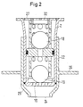
- the device to be let into a container floor 1 has an outer housing 2 on, which is formed in its longer lower region 3 as a smooth pipe section 4 is, which is closed on its underside 5 with a cover 6 substantially is.
- a funnel-shaped pipe section 7 attached, the 8 at the upper end with an outward Mounting flange 9 ends.
- a hole 10 is central in and around the cover 6 Several holes 10 are arranged concentrically.
- a valve basket 11 can be removed from the upper end 8 into the outer housing 2 used.
- the valve basket 11 has a cylindrical valve plate 12, which with a central through opening 13 is provided and the outer diameter is the inner diameter of the outer housing 2 corresponds in its smooth tube section 4.
- the Valve plate 12 separates the valve basket 11 into an upper valve chamber 14 and a lower one Valve chamber 15, both of which are connected to one another via the central through opening 13 are connected.
- the central through opening 13 forms in the area of the upper valve chamber 14 an upper valve seat 16 and in the region of the lower valve chamber 15 a lower valve seat 17.
- Located in the upper valve chamber 14 the first floating closure member 18 and in the lower valve chamber 15 the second floating closure member 19, both preferably as a hollow Plastic balls are formed.
- the valve seats 16 and 17 are the surface courses the closing members 18, 19 adapted sealing.
- the device is built into a multi-layer container floor 1 arranged in such a way that at the upper end 8 of the outer housing 2nd provided mounting flange 9 on its top on a bottom 20 a the cargo space facing inner plate 21 of the container base 1 is attached sealingly is, while the outer housing 2 with its underside 5 in a cup-shaped Receptacle 22 is arranged on an outer slat of the container bottom 1 is attached.
- the receptacle 22 protrudes downward over the outer plate 23.
- Adjacent to the outer plate 23 is the inclusion of one Surround ring flange 26 with which it is attached to the outer plate 23
- valve cage 11 inserted so far into the outer housing 2 until one be at its upper end sensitive annular retaining flange 27 in the region of the enlarged pipe section 7 bears against the upper end 8 of the outer housing 2. It engages in The outer circumference 28 of the valve plate 12 is provided in a circumferential groove 29 Sealing ring 30 sealing on the inner wall 31 of the outer housing 2 in Area of his smooth pipe section 4.
- the interior of the container becomes there located water first in the area of the upper valve chamber 14 and its surroundings collected in the upper area of the outer housing 2 until the first closing member 1 floats and the central through opening 13 of the valve plate 12 releases so that the water can pass through this through opening 13 and can close to the outside via the holes 10 in the cover 6.
- the outside pressing water so-called green water
- An automatic drainage device is preferably made of non-corrosive metals or made of plastic. It has been shown that the use of plastic (e.g. for the receptacle 22) is therefore particularly important is advantageous because it creates thermal bridges between the interior of the container and the outside air can be reliably avoided.
- the drainage device is easy and safe to use, has a long service life and due to their simple and safe construction can be permanent that their functionality is maintained.
Landscapes
- Engineering & Computer Science (AREA)
- Mechanical Engineering (AREA)
- General Engineering & Computer Science (AREA)
- Packages (AREA)
- Refuse Collection And Transfer (AREA)
- Details Of Rigid Or Semi-Rigid Containers (AREA)
- Ship Loading And Unloading (AREA)
- Body Structure For Vehicles (AREA)
- Pallets (AREA)
- Load-Engaging Elements For Cranes (AREA)
- Packaging Of Machine Parts And Wound Products (AREA)
- Sink And Installation For Waste Water (AREA)
- Devices For Dispensing Beverages (AREA)
Description
- Figur 1
- einen zentralen Längsschnitt durch eine erfindungsgemäße Entwässerungsvorrichtung in schematischer Darstellung,
- Figur 2
- eine Darstellung gemäß Figur 1 mit einer zur Befestigung der Vorrichtung in einem Containerboden vorgesehenen Aufnahme
- Figur 3
- eine Darstellung gemäß Figur 1 in ihrer Anordnung in einem Mehrschichtboden eines Kühlcontainers.
Claims (9)
- Anordnung einer selbsttätigen Entwässerungsvorrichtung für Frachtcontainer oder andere Ladungen aufnehmende Räume mit einem im wesentlichen zylindrischen Außengehäuse (2) mit offenen Endabschnitten und einer mit einer Durchgangsöffnung (13) versehenen Ventilplatte (12) zwischen den beiden Endabschnitten, der auf der Oberseite ein erstes aufschwimmfähiges Schließorgan (18) für die Durchgangsöffnung (13) zugeordnet ist, dadurch gekennzeichnet, daß das Außengehäuse (2) in einem in Mehrschichtenbauweise konstruierten Containerboden (1) in der Weise angeordnet ist, daß ein am Außengehäuse (2) an seinem oberen Ende (8) vorgesehener Befestigungsflansch (9) an einer Unterseite (20) einer dem Laderaum zugekehrten Innenplatte (21) abdichtend befestigt ist und das Außengehäuse (2) mit einer Unterseite (5) in einer becherförmigen Aufnahme (22) angeordnet ist, die an einer Außenplatte (23) des Containerbodens (1) befestigt ist und daß der Ventilplatte (12) auf ihrer Unterseite ein zweites aufschwimmfähiges Schließorgan (19) für die Durchgangsöffnung (13) zugeordnet ist.
- Anordnung einer Entwässerungsvorrichtung nach Anspruch 1, dadurch gekennzeichnet, daß die Ventilplatte (12) mit einem Ventilkorb (11) verbunden ist, der in das Außengehäuse (2) herausnehmbar eingesetzt ist.
- Anordnung einer Entwässerungsvorrichtung nach Anspruch 2, dadurch gekennzeichnet, daß die Ventilplatte (12) den Ventilkorb (11) in eine obere Ventilkammer (14) und in eine untere Ventilkammer (15) unterteilt.
- Anordnung einer Entwässerungsvorrichtung nach Anspruch 3, dadurch gekennzeichnet, daß das erste aufschwimmfähige Schließorgan (18) in der oberen Ventilkammer (14) und das zweite aufschwimmfähige Schließorgan (19) in der unteren Ventilkammer (15) angeordnet sind.
- Anordnung einer Entwässerungsvorrichtung nach Anspruch 1 bis 4, dadurch gekennzeichnet, daß die Schließorgane (18, 19) aus Kugeln bestehen.
- Anordnung einer Entwässerungsvorrichtung nach Anspruch 1 bis 5, dadurch gekennzeichnet, daß die Ventilplatte (12) im Bereich seiner Durchgangsöffnung (13) an seiner Oberseite einen oberen Ventilsitz (16) und an seiner Unterseite einen unteren Ventilsitz (17) ausbildet, die jeweils den Oberflächen der Schließorgane (18, 19) abdichtend angepaßt sind.
- Anordnung einer Entwässerungsvorrichtung nach Anspruch 1 bis 6, dadurch gekennzeichnet, daß die Aufnahme (22) über die Außenplatte (23) nach unten herausragt.
- Anordnung einer Entwässerungsvorrichtung nach Anspruch 1 - 7, dadurch gekennzeichnet, daß die Aufnahme (22) an ihrem unteren Ende (24) ein, Löcher (10) in einem unteren Deckel (6) des Außengehäuses (2) abschirmendes, tüllenartiges Endstück (25) aufweist.
- Anordnung einer Entwässerungsvorrichtung nach Anspruch 1 - 8, dadurch gekennzeichnet, daß die Aufnahme (22) benachbart zur Außenplatte (23) einen Ringflansch (26) aufweist, mit dem sie an der Außenplatte (23) befestigt ist.
Applications Claiming Priority (2)
| Application Number | Priority Date | Filing Date | Title |
|---|---|---|---|
| DE19649864 | 1996-12-02 | ||
| DE19649864A DE19649864A1 (de) | 1996-12-02 | 1996-12-02 | Selbsttätige Entwässerungsvorrichtung für Frachtcontainer oder andere Ladungen aufnehmende Räume |
Publications (2)
| Publication Number | Publication Date |
|---|---|
| EP0850855A1 EP0850855A1 (de) | 1998-07-01 |
| EP0850855B1 true EP0850855B1 (de) | 2001-05-23 |
Family
ID=7813348
Family Applications (1)
| Application Number | Title | Priority Date | Filing Date |
|---|---|---|---|
| EP97121026A Expired - Lifetime EP0850855B1 (de) | 1996-12-02 | 1997-11-29 | Selbsttätige Entwässerungsvorrichtung für Frachtcontainer oder andere Ladungen aufnehmende Räume |
Country Status (16)
| Country | Link |
|---|---|
| US (1) | US6131605A (de) |
| EP (1) | EP0850855B1 (de) |
| JP (1) | JP3928900B2 (de) |
| KR (1) | KR100519489B1 (de) |
| CN (1) | CN1072172C (de) |
| AT (1) | ATE201372T1 (de) |
| CZ (1) | CZ290236B6 (de) |
| DE (2) | DE19649864A1 (de) |
| DK (1) | DK0850855T3 (de) |
| ES (1) | ES2158430T3 (de) |
| GR (1) | GR3036337T3 (de) |
| PL (1) | PL183675B1 (de) |
| PT (1) | PT850855E (de) |
| RO (1) | RO113544B1 (de) |
| TW (1) | TW376375B (de) |
| ZA (1) | ZA9710631B (de) |
Families Citing this family (22)
| Publication number | Priority date | Publication date | Assignee | Title |
|---|---|---|---|---|
| DE19649864A1 (de) * | 1996-12-02 | 1998-06-04 | Graaff Vertriebs Gmbh | Selbsttätige Entwässerungsvorrichtung für Frachtcontainer oder andere Ladungen aufnehmende Räume |
| US6564820B2 (en) * | 2001-10-09 | 2003-05-20 | United Technologies Corporation | Gas flow stop device |
| US6848465B1 (en) * | 2002-04-17 | 2005-02-01 | Robert H. Wager Co., Inc. | Dual-action vent check valve |
| CN1323016C (zh) * | 2003-04-02 | 2007-06-27 | 中国国际海运集装箱(集团)股份有限公司 | 一种排水装置 |
| PL1683742T3 (pl) * | 2005-01-22 | 2007-09-28 | Waggonbau Graaff Gmbh | Zawór do odwadniania kontenerów frachtowych i tym podobnych |
| US20080000527A1 (en) * | 2006-06-28 | 2008-01-03 | Stout, Tacconelli & Associates, Inc. | Apparatus and Method for Slow Transport of a Liquid Body |
| GB0820039D0 (en) * | 2008-11-03 | 2008-12-10 | Priestly Toby J | Improvements in valves |
| CN101603608B (zh) * | 2009-06-30 | 2011-02-09 | 安东石油技术(集团)有限公司 | 一种集成式水介质单向阀 |
| US8136466B2 (en) * | 2009-08-21 | 2012-03-20 | Gsc Technologies Corporation | Self-bailing watercraft valve |
| EP2743412B1 (de) * | 2012-12-11 | 2015-11-18 | Khaled Jafar Al-Hasan | Abfluss |
| DE102013206402A1 (de) * | 2013-04-11 | 2014-10-16 | Siemens Aktiengesellschaft | Entwässerungsstopfen für einen Schienenfahrzeugboden |
| DE102013222997A1 (de) * | 2013-11-12 | 2015-05-13 | Siemens Aktiengesellschaft | Entwässerungsvorrichtung für einen Fahrzeug-Wagenkasten, Fahrzeug-Wagenkasten-Unterbau mit Entwässerungsvorrichtung und entsprechender Fahrzeug-Wagenkasten |
| EP3160599B1 (de) | 2014-06-24 | 2019-08-07 | Kurion, Inc. | Mobiles verarbeitungssystem zur entfernung gefährlicher und radioaktiver isotope |
| KR20160041468A (ko) * | 2014-10-07 | 2016-04-18 | 강은진 | 방수 기능을 갖는 공조 장치 |
| US10451307B2 (en) | 2016-04-15 | 2019-10-22 | Hoffman Enclosures, Inc. | Float drain |
| CN107323882B (zh) * | 2017-06-20 | 2023-03-17 | 广东富华机械装备制造有限公司 | 一种排水装置 |
| US10472816B2 (en) * | 2017-07-26 | 2019-11-12 | Justin Griebel | Backflow valve assembly |
| CN109592234A (zh) * | 2019-01-22 | 2019-04-09 | 太仓中集冷藏物流装备有限公司 | 用于冷藏集装箱的漏水器 |
| CN110654731B (zh) * | 2019-10-30 | 2024-09-24 | 青岛中集冷藏箱制造有限公司 | 漏水器及具有其的冷藏集装箱 |
| US20240301924A1 (en) * | 2023-03-07 | 2024-09-12 | Arctic Cat Inc. | Duct valve for clutch assembly in off-road vehicles |
| EP4461653B1 (de) * | 2023-05-11 | 2025-11-05 | Goodrich Lighting Systems GmbH & Co. KG | Flugzeugaussenleuchte, flugzeug mit einer flugzeugaussenleuchte und verfahren zum ableiten einer flüssigkeit aus einer flugzeugaussenleuchte |
| EP4477559B1 (de) | 2023-06-13 | 2026-01-21 | Goodrich Lighting Systems GmbH & Co. KG | Flugzeugaussenleuchte, flugzeug mit einer flugzeugaussenleuchte und verfahren zum ableiten einer flüssigkeit aus einer flugzeugaussenleuchte |
Family Cites Families (19)
| Publication number | Priority date | Publication date | Assignee | Title |
|---|---|---|---|---|
| US102823A (en) * | 1870-05-10 | Improvement in life-preservers | ||
| US7A (en) * | 1836-08-10 | Thomas Blanchard | Machine for boring holes and cutting lanyard-scores in deadeyes | |
| US859540A (en) * | 1906-05-07 | 1907-07-09 | William R Bonnell | Trap. |
| US1176785A (en) * | 1915-06-21 | 1916-03-28 | Richard R Stielow | Valve. |
| US1953007A (en) * | 1930-07-24 | 1934-03-27 | Westinghouse Air Brake Co | Check valve device |
| US2199673A (en) * | 1938-04-25 | 1940-05-07 | Ronning Adolph | Drain |
| US2767552A (en) * | 1955-03-11 | 1956-10-23 | Henry H Clute | Fill valve for liquefied petroleum gas tanks |
| US2920644A (en) * | 1957-03-25 | 1960-01-12 | Culligan Inc | Liquid level valve assembly |
| US3273514A (en) * | 1965-06-17 | 1966-09-20 | Lloyd F Bender | Fluid conveying apparatus |
| US3620240A (en) * | 1970-03-13 | 1971-11-16 | William Bogdanski | Double check valve vent |
| US3759281A (en) * | 1971-11-19 | 1973-09-18 | Grupul Ind Pentru Foraj Si Ext | Cementing float shoe |
| US4524794A (en) * | 1983-12-19 | 1985-06-25 | Haines Frederick K | Air release and anti-siphon valve |
| US4640304A (en) * | 1985-03-22 | 1987-02-03 | Baird Manufacturing Company | Overflow vent valve |
| DE9102782U1 (de) * | 1991-03-08 | 1991-06-27 | Graaff GmbH, 3210 Elze | Selbsttätige Entwässerungsvorrichtung für Frachtcontainer |
| US5524495A (en) * | 1992-06-22 | 1996-06-11 | Vortox Company | Liquid sampling devices and method |
| US5782258A (en) * | 1995-12-11 | 1998-07-21 | Alfmeier Corporation | Vapor recovery fuel tank system |
| US5662138A (en) * | 1996-06-12 | 1997-09-02 | Wang; Wen-Hsing | Drop head structure |
| DE19649864A1 (de) * | 1996-12-02 | 1998-06-04 | Graaff Vertriebs Gmbh | Selbsttätige Entwässerungsvorrichtung für Frachtcontainer oder andere Ladungen aufnehmende Räume |
| JP6245754B2 (ja) * | 2014-03-27 | 2017-12-13 | クオリカプス株式会社 | インクジェットマーキング装置および方法 |
-
1996
- 1996-12-02 DE DE19649864A patent/DE19649864A1/de not_active Withdrawn
-
1997
- 1997-11-26 CN CN97122647A patent/CN1072172C/zh not_active Expired - Lifetime
- 1997-11-26 ZA ZA9710631A patent/ZA9710631B/xx unknown
- 1997-11-27 PL PL97323373A patent/PL183675B1/pl not_active IP Right Cessation
- 1997-11-29 DK DK97121026T patent/DK0850855T3/da active
- 1997-11-29 AT AT97121026T patent/ATE201372T1/de not_active IP Right Cessation
- 1997-11-29 PT PT97121026T patent/PT850855E/pt unknown
- 1997-11-29 EP EP97121026A patent/EP0850855B1/de not_active Expired - Lifetime
- 1997-11-29 DE DE59703594T patent/DE59703594D1/de not_active Expired - Lifetime
- 1997-11-29 ES ES97121026T patent/ES2158430T3/es not_active Expired - Lifetime
- 1997-12-02 CZ CZ19973815A patent/CZ290236B6/cs not_active IP Right Cessation
- 1997-12-02 JP JP33144697A patent/JP3928900B2/ja not_active Expired - Fee Related
- 1997-12-02 RO RO97-02214A patent/RO113544B1/ro unknown
- 1997-12-02 KR KR1019970065218A patent/KR100519489B1/ko not_active Expired - Fee Related
- 1997-12-02 US US08/982,665 patent/US6131605A/en not_active Expired - Fee Related
- 1997-12-11 TW TW086118661A patent/TW376375B/zh not_active IP Right Cessation
-
2001
- 2001-08-07 GR GR20010401189T patent/GR3036337T3/el not_active IP Right Cessation
Also Published As
| Publication number | Publication date |
|---|---|
| CZ381597A3 (cs) | 1999-05-12 |
| CN1072172C (zh) | 2001-10-03 |
| DK0850855T3 (da) | 2001-08-27 |
| DE59703594D1 (de) | 2001-06-28 |
| US6131605A (en) | 2000-10-17 |
| KR100519489B1 (ko) | 2007-11-09 |
| ZA9710631B (en) | 1998-04-01 |
| TW376375B (en) | 1999-12-11 |
| RO113544B1 (ro) | 1998-08-28 |
| ATE201372T1 (de) | 2001-06-15 |
| PL323373A1 (en) | 1998-06-08 |
| HK1011195A1 (en) | 1999-07-09 |
| EP0850855A1 (de) | 1998-07-01 |
| GR3036337T3 (en) | 2001-11-30 |
| DE19649864A1 (de) | 1998-06-04 |
| JP3928900B2 (ja) | 2007-06-13 |
| JPH10236583A (ja) | 1998-09-08 |
| ES2158430T3 (es) | 2001-09-01 |
| KR19980063687A (ko) | 1998-10-07 |
| PL183675B1 (pl) | 2002-06-28 |
| CN1184068A (zh) | 1998-06-10 |
| PT850855E (pt) | 2001-09-28 |
| CZ290236B6 (cs) | 2002-06-12 |
Similar Documents
| Publication | Publication Date | Title |
|---|---|---|
| EP0850855A1 (de) | Selbsttätige Entwässerungsvorrichtung für Frachtcontainer oder andere Ladungen aufnehmende Räume | |
| EP0503544B1 (de) | Selbsttätige Entwässerungsvorrichtung für Frachtcontainer | |
| DE2401183A1 (de) | Filter | |
| DE69629208T2 (de) | Treibstofffilter mit verbesserter verbindung zu einem behälter für verunreinigungen | |
| DE1407951A1 (de) | Luftfilteranlage | |
| EP1683742B1 (de) | Ventil zur Entwässerung von Frachtcontainern u.a. | |
| DE7722622U1 (de) | Vorrichtung zum trennen von fluessigkeiten unterschiedlichen spezifischen gewichts | |
| DE29620795U1 (de) | Selbsttätige Entwässerungsvorrichtung für Frachtcontainer oder andere Ladungen aufnehmende Räume | |
| DE4042326A1 (de) | Abdeckung fuer fluessigkeitsbecken | |
| DE112019001740T5 (de) | Geruchsverschluss | |
| EP0634530B1 (de) | Geruchverschlussfür eine Ablaufarmatur | |
| EP1127988A2 (de) | Bodenablauf mit Schwimmerverschluss | |
| EP0858417B1 (de) | Vorrichtung zum Druckausgleich in unter Unterdruck stehenden Gefässen | |
| DE4416462A1 (de) | Entlüftungsvorrichtung für eine Toilette | |
| DE2714530A1 (de) | Filtergeraet fuer aquarien | |
| DE202004007793U1 (de) | Geruchverschluss für Seiteneinläufe | |
| DE4040015C1 (de) | ||
| DE19732737C1 (de) | Anschlußarmatur für Filtertanks, insbesondere für Wasser | |
| DE9412394U1 (de) | Abscheider für von Abwasser mitgeführte organische Leichtstoffe | |
| DE2950276A1 (de) | Vorrichtung zum abscheiden von schwimmstoffen aus abwasser | |
| DE102019105414A1 (de) | Flüssigkeitsfilter | |
| DE202023101797U1 (de) | Ablaufanordnung | |
| DE29811974U1 (de) | Ein regen- und spritzwasserdichtes Behältnis mit integrierter automatischer Be- und Entlüftung geeignet für die Anbringung an Anhänger und Fahrzeugen jeglicher Art | |
| DE9417456U1 (de) | Abdicht- und Lüftungsvorrichtungen für Gefäße und andere Behälter | |
| DE8904909U1 (de) | Koaleszenzabscheider für Leichtflüssigkeiten |
Legal Events
| Date | Code | Title | Description |
|---|---|---|---|
| PUAI | Public reference made under article 153(3) epc to a published international application that has entered the european phase |
Free format text: ORIGINAL CODE: 0009012 |
|
| AK | Designated contracting states |
Kind code of ref document: A1 Designated state(s): AT BE CH DE DK ES FI FR GB GR IE IT LI LU MC NL PT SE |
|
| AX | Request for extension of the european patent |
Free format text: AL;LT;LV;MK;RO;SI |
|
| 17P | Request for examination filed |
Effective date: 19981204 |
|
| AKX | Designation fees paid |
Free format text: AT BE CH DE DK ES FI FR GB GR IE IT LI LU MC NL PT SE |
|
| RBV | Designated contracting states (corrected) |
Designated state(s): AT BE CH DE DK ES FI FR GB GR IE IT LI LU MC NL PT SE |
|
| 17Q | First examination report despatched |
Effective date: 19990713 |
|
| GRAG | Despatch of communication of intention to grant |
Free format text: ORIGINAL CODE: EPIDOS AGRA |
|
| GRAG | Despatch of communication of intention to grant |
Free format text: ORIGINAL CODE: EPIDOS AGRA |
|
| GRAH | Despatch of communication of intention to grant a patent |
Free format text: ORIGINAL CODE: EPIDOS IGRA |
|
| RAP1 | Party data changed (applicant data changed or rights of an application transferred) |
Owner name: WAGGONBAU ELZE GMBH & CO. BESITZ KG |
|
| GRAH | Despatch of communication of intention to grant a patent |
Free format text: ORIGINAL CODE: EPIDOS IGRA |
|
| GRAA | (expected) grant |
Free format text: ORIGINAL CODE: 0009210 |
|
| AK | Designated contracting states |
Kind code of ref document: B1 Designated state(s): AT BE CH DE DK ES FI FR GB GR IE IT LI LU MC NL PT SE |
|
| REF | Corresponds to: |
Ref document number: 201372 Country of ref document: AT Date of ref document: 20010615 Kind code of ref document: T |
|
| REG | Reference to a national code |
Ref country code: CH Ref legal event code: EP |
|
| GBT | Gb: translation of ep patent filed (gb section 77(6)(a)/1977) |
Effective date: 20010523 |
|
| REG | Reference to a national code |
Ref country code: CH Ref legal event code: NV Representative=s name: TROESCH SCHEIDEGGER WERNER AG * TROESCH SCHEIDEGGE |
|
| REF | Corresponds to: |
Ref document number: 59703594 Country of ref document: DE Date of ref document: 20010628 |
|
| REG | Reference to a national code |
Ref country code: IE Ref legal event code: FG4D Free format text: GERMAN |
|
| ITF | It: translation for a ep patent filed | ||
| REG | Reference to a national code |
Ref country code: DK Ref legal event code: T3 |
|
| REG | Reference to a national code |
Ref country code: ES Ref legal event code: FG2A Ref document number: 2158430 Country of ref document: ES Kind code of ref document: T3 |
|
| REG | Reference to a national code |
Ref country code: PT Ref legal event code: SC4A Free format text: AVAILABILITY OF NATIONAL TRANSLATION Effective date: 20010709 |
|
| ET | Fr: translation filed | ||
| PG25 | Lapsed in a contracting state [announced via postgrant information from national office to epo] |
Ref country code: MC Free format text: LAPSE BECAUSE OF NON-PAYMENT OF DUE FEES Effective date: 20011129 |
|
| REG | Reference to a national code |
Ref country code: GB Ref legal event code: IF02 |
|
| PLBE | No opposition filed within time limit |
Free format text: ORIGINAL CODE: 0009261 |
|
| STAA | Information on the status of an ep patent application or granted ep patent |
Free format text: STATUS: NO OPPOSITION FILED WITHIN TIME LIMIT |
|
| 26N | No opposition filed | ||
| REG | Reference to a national code |
Ref country code: GB Ref legal event code: 732E |
|
| REG | Reference to a national code |
Ref country code: CH Ref legal event code: PUE Owner name: POLYEARN DEVELOPMENT CORP. Free format text: WAGGONBAU ELZE GMBH & CO. BESITZ KG#HEINRICH-NAGEL-STRASSE 1#31008 ELZE (DE) -TRANSFER TO- POLYEARN DEVELOPMENT CORP.#TRIDENT CHAMBERS, P.O. BOX 146#ROAD TOWN, TORTOLA (VG) Ref country code: CH Ref legal event code: NV Representative=s name: ABREMA AGENCE BREVETS ET MARQUES GANGUILLET & HUMP |
|
| NLS | Nl: assignments of ep-patents |
Owner name: POLYEARN DEVELOPMENT CORP. Effective date: 20051125 |
|
| REG | Reference to a national code |
Ref country code: FR Ref legal event code: TP |
|
| PGFP | Annual fee paid to national office [announced via postgrant information from national office to epo] |
Ref country code: SE Payment date: 20061026 Year of fee payment: 10 |
|
| PGFP | Annual fee paid to national office [announced via postgrant information from national office to epo] |
Ref country code: LU Payment date: 20061027 Year of fee payment: 10 |
|
| PGFP | Annual fee paid to national office [announced via postgrant information from national office to epo] |
Ref country code: FI Payment date: 20061123 Year of fee payment: 10 Ref country code: BE Payment date: 20061123 Year of fee payment: 10 |
|
| PGFP | Annual fee paid to national office [announced via postgrant information from national office to epo] |
Ref country code: PT Payment date: 20061124 Year of fee payment: 10 Ref country code: AT Payment date: 20061124 Year of fee payment: 10 |
|
| PGFP | Annual fee paid to national office [announced via postgrant information from national office to epo] |
Ref country code: DK Payment date: 20061127 Year of fee payment: 10 |
|
| PGFP | Annual fee paid to national office [announced via postgrant information from national office to epo] |
Ref country code: IE Payment date: 20061128 Year of fee payment: 10 |
|
| PGFP | Annual fee paid to national office [announced via postgrant information from national office to epo] |
Ref country code: GR Payment date: 20061129 Year of fee payment: 10 |
|
| PGFP | Annual fee paid to national office [announced via postgrant information from national office to epo] |
Ref country code: IT Payment date: 20061130 Year of fee payment: 10 Ref country code: ES Payment date: 20061130 Year of fee payment: 10 |
|
| PGFP | Annual fee paid to national office [announced via postgrant information from national office to epo] |
Ref country code: CH Payment date: 20061228 Year of fee payment: 10 |
|
| REG | Reference to a national code |
Ref country code: PT Ref legal event code: PC4A Owner name: POLYEARN DEVELOPMENT CORP., GB Effective date: 20070410 |
|
| BERE | Be: lapsed |
Owner name: *POLYEARN DEVELOPMENTT CORP. Effective date: 20071130 |
|
| REG | Reference to a national code |
Ref country code: PT Ref legal event code: MM4A Free format text: LAPSE DUE TO NON-PAYMENT OF FEES Effective date: 20080529 |
|
| REG | Reference to a national code |
Ref country code: DK Ref legal event code: EBP |
|
| EUG | Se: european patent has lapsed | ||
| PG25 | Lapsed in a contracting state [announced via postgrant information from national office to epo] |
Ref country code: LI Free format text: LAPSE BECAUSE OF NON-PAYMENT OF DUE FEES Effective date: 20071130 Ref country code: FI Free format text: LAPSE BECAUSE OF NON-PAYMENT OF DUE FEES Effective date: 20071129 Ref country code: CH Free format text: LAPSE BECAUSE OF NON-PAYMENT OF DUE FEES Effective date: 20071130 |
|
| REG | Reference to a national code |
Ref country code: CH Ref legal event code: PL |
|
| REG | Reference to a national code |
Ref country code: IE Ref legal event code: MM4A |
|
| PG25 | Lapsed in a contracting state [announced via postgrant information from national office to epo] |
Ref country code: AT Free format text: LAPSE BECAUSE OF NON-PAYMENT OF DUE FEES Effective date: 20071129 |
|
| PG25 | Lapsed in a contracting state [announced via postgrant information from national office to epo] |
Ref country code: BE Free format text: LAPSE BECAUSE OF NON-PAYMENT OF DUE FEES Effective date: 20071130 Ref country code: PT Free format text: LAPSE BECAUSE OF NON-PAYMENT OF DUE FEES Effective date: 20080529 |
|
| PG25 | Lapsed in a contracting state [announced via postgrant information from national office to epo] |
Ref country code: SE Free format text: LAPSE BECAUSE OF NON-PAYMENT OF DUE FEES Effective date: 20071130 Ref country code: IE Free format text: LAPSE BECAUSE OF NON-PAYMENT OF DUE FEES Effective date: 20071129 Ref country code: DK Free format text: LAPSE BECAUSE OF NON-PAYMENT OF DUE FEES Effective date: 20071130 |
|
| PGFP | Annual fee paid to national office [announced via postgrant information from national office to epo] |
Ref country code: NL Payment date: 20081224 Year of fee payment: 12 |
|
| REG | Reference to a national code |
Ref country code: ES Ref legal event code: FD2A Effective date: 20071130 |
|
| PG25 | Lapsed in a contracting state [announced via postgrant information from national office to epo] |
Ref country code: ES Free format text: LAPSE BECAUSE OF NON-PAYMENT OF DUE FEES Effective date: 20071130 |
|
| PGFP | Annual fee paid to national office [announced via postgrant information from national office to epo] |
Ref country code: FR Payment date: 20081128 Year of fee payment: 12 |
|
| PG25 | Lapsed in a contracting state [announced via postgrant information from national office to epo] |
Ref country code: GR Free format text: LAPSE BECAUSE OF NON-PAYMENT OF DUE FEES Effective date: 20080605 |
|
| PGFP | Annual fee paid to national office [announced via postgrant information from national office to epo] |
Ref country code: GB Payment date: 20081229 Year of fee payment: 12 |
|
| PG25 | Lapsed in a contracting state [announced via postgrant information from national office to epo] |
Ref country code: LU Free format text: LAPSE BECAUSE OF NON-PAYMENT OF DUE FEES Effective date: 20071129 Ref country code: IT Free format text: LAPSE BECAUSE OF NON-PAYMENT OF DUE FEES Effective date: 20071129 |
|
| REG | Reference to a national code |
Ref country code: NL Ref legal event code: V1 Effective date: 20100601 |
|
| GBPC | Gb: european patent ceased through non-payment of renewal fee |
Effective date: 20091129 |
|
| REG | Reference to a national code |
Ref country code: FR Ref legal event code: ST Effective date: 20100730 |
|
| PG25 | Lapsed in a contracting state [announced via postgrant information from national office to epo] |
Ref country code: NL Free format text: LAPSE BECAUSE OF NON-PAYMENT OF DUE FEES Effective date: 20100601 Ref country code: FR Free format text: LAPSE BECAUSE OF NON-PAYMENT OF DUE FEES Effective date: 20091130 |
|
| PG25 | Lapsed in a contracting state [announced via postgrant information from national office to epo] |
Ref country code: GB Free format text: LAPSE BECAUSE OF NON-PAYMENT OF DUE FEES Effective date: 20091129 |
|
| PGFP | Annual fee paid to national office [announced via postgrant information from national office to epo] |
Ref country code: DE Payment date: 20101025 Year of fee payment: 14 |
|
| REG | Reference to a national code |
Ref country code: DE Ref legal event code: R119 Ref document number: 59703594 Country of ref document: DE Effective date: 20130601 |
|
| PG25 | Lapsed in a contracting state [announced via postgrant information from national office to epo] |
Ref country code: DE Free format text: LAPSE BECAUSE OF NON-PAYMENT OF DUE FEES Effective date: 20130601 |