EP0850151B1 - Einrichtung zur rollstabilisierung eines fahrzeugs - Google Patents
Einrichtung zur rollstabilisierung eines fahrzeugs Download PDFInfo
- Publication number
- EP0850151B1 EP0850151B1 EP97932827A EP97932827A EP0850151B1 EP 0850151 B1 EP0850151 B1 EP 0850151B1 EP 97932827 A EP97932827 A EP 97932827A EP 97932827 A EP97932827 A EP 97932827A EP 0850151 B1 EP0850151 B1 EP 0850151B1
- Authority
- EP
- European Patent Office
- Prior art keywords
- hydraulic
- valve
- pressure
- control
- pump
- Prior art date
- Legal status (The legal status is an assumption and is not a legal conclusion. Google has not performed a legal analysis and makes no representation as to the accuracy of the status listed.)
- Expired - Lifetime
Links
Images


Classifications
-
- B—PERFORMING OPERATIONS; TRANSPORTING
- B60—VEHICLES IN GENERAL
- B60G—VEHICLE SUSPENSION ARRANGEMENTS
- B60G21/00—Interconnection systems for two or more resiliently-suspended wheels, e.g. for stabilising a vehicle body with respect to acceleration, deceleration or centrifugal forces
- B60G21/02—Interconnection systems for two or more resiliently-suspended wheels, e.g. for stabilising a vehicle body with respect to acceleration, deceleration or centrifugal forces permanently interconnected
- B60G21/06—Interconnection systems for two or more resiliently-suspended wheels, e.g. for stabilising a vehicle body with respect to acceleration, deceleration or centrifugal forces permanently interconnected fluid
- B60G21/073—Interconnection systems for two or more resiliently-suspended wheels, e.g. for stabilising a vehicle body with respect to acceleration, deceleration or centrifugal forces permanently interconnected fluid between wheels on the same axle but on different sides of the vehicle, i.e. the left and right wheel suspensions being interconnected
-
- B—PERFORMING OPERATIONS; TRANSPORTING
- B60—VEHICLES IN GENERAL
- B60G—VEHICLE SUSPENSION ARRANGEMENTS
- B60G17/00—Resilient suspensions having means for adjusting the spring or vibration-damper characteristics, for regulating the distance between a supporting surface and a sprung part of vehicle or for locking suspension during use to meet varying vehicular or surface conditions, e.g. due to speed or load
- B60G17/015—Resilient suspensions having means for adjusting the spring or vibration-damper characteristics, for regulating the distance between a supporting surface and a sprung part of vehicle or for locking suspension during use to meet varying vehicular or surface conditions, e.g. due to speed or load the regulating means comprising electric or electronic elements
- B60G17/016—Resilient suspensions having means for adjusting the spring or vibration-damper characteristics, for regulating the distance between a supporting surface and a sprung part of vehicle or for locking suspension during use to meet varying vehicular or surface conditions, e.g. due to speed or load the regulating means comprising electric or electronic elements characterised by their responsiveness, when the vehicle is travelling, to specific motion, a specific condition, or driver input
- B60G17/0162—Resilient suspensions having means for adjusting the spring or vibration-damper characteristics, for regulating the distance between a supporting surface and a sprung part of vehicle or for locking suspension during use to meet varying vehicular or surface conditions, e.g. due to speed or load the regulating means comprising electric or electronic elements characterised by their responsiveness, when the vehicle is travelling, to specific motion, a specific condition, or driver input mainly during a motion involving steering operation, e.g. cornering, overtaking
-
- B—PERFORMING OPERATIONS; TRANSPORTING
- B60—VEHICLES IN GENERAL
- B60G—VEHICLE SUSPENSION ARRANGEMENTS
- B60G17/00—Resilient suspensions having means for adjusting the spring or vibration-damper characteristics, for regulating the distance between a supporting surface and a sprung part of vehicle or for locking suspension during use to meet varying vehicular or surface conditions, e.g. due to speed or load
- B60G17/02—Spring characteristics, e.g. mechanical springs and mechanical adjusting means
- B60G17/04—Spring characteristics, e.g. mechanical springs and mechanical adjusting means fluid spring characteristics
- B60G17/056—Regulating distributors or valves for hydropneumatic systems
-
- B—PERFORMING OPERATIONS; TRANSPORTING
- B60—VEHICLES IN GENERAL
- B60G—VEHICLE SUSPENSION ARRANGEMENTS
- B60G21/00—Interconnection systems for two or more resiliently-suspended wheels, e.g. for stabilising a vehicle body with respect to acceleration, deceleration or centrifugal forces
- B60G21/02—Interconnection systems for two or more resiliently-suspended wheels, e.g. for stabilising a vehicle body with respect to acceleration, deceleration or centrifugal forces permanently interconnected
- B60G21/04—Interconnection systems for two or more resiliently-suspended wheels, e.g. for stabilising a vehicle body with respect to acceleration, deceleration or centrifugal forces permanently interconnected mechanically
- B60G21/05—Interconnection systems for two or more resiliently-suspended wheels, e.g. for stabilising a vehicle body with respect to acceleration, deceleration or centrifugal forces permanently interconnected mechanically between wheels on the same axle but on different sides of the vehicle, i.e. the left and right wheel suspensions being interconnected
- B60G21/055—Stabiliser bars
- B60G21/0551—Mounting means therefor
- B60G21/0553—Mounting means therefor adjustable
-
- B—PERFORMING OPERATIONS; TRANSPORTING
- B60—VEHICLES IN GENERAL
- B60G—VEHICLE SUSPENSION ARRANGEMENTS
- B60G21/00—Interconnection systems for two or more resiliently-suspended wheels, e.g. for stabilising a vehicle body with respect to acceleration, deceleration or centrifugal forces
- B60G21/10—Interconnection systems for two or more resiliently-suspended wheels, e.g. for stabilising a vehicle body with respect to acceleration, deceleration or centrifugal forces not permanently interconnected, e.g. operative only on acceleration, only on deceleration or only at off-straight position of steering
-
- B—PERFORMING OPERATIONS; TRANSPORTING
- B60—VEHICLES IN GENERAL
- B60G—VEHICLE SUSPENSION ARRANGEMENTS
- B60G2202/00—Indexing codes relating to the type of spring, damper or actuator
- B60G2202/40—Type of actuator
- B60G2202/41—Fluid actuator
- B60G2202/413—Hydraulic actuator
-
- B—PERFORMING OPERATIONS; TRANSPORTING
- B60—VEHICLES IN GENERAL
- B60G—VEHICLE SUSPENSION ARRANGEMENTS
- B60G2800/00—Indexing codes relating to the type of movement or to the condition of the vehicle and to the end result to be achieved by the control action
- B60G2800/01—Attitude or posture control
- B60G2800/012—Rolling condition
-
- F—MECHANICAL ENGINEERING; LIGHTING; HEATING; WEAPONS; BLASTING
- F15—FLUID-PRESSURE ACTUATORS; HYDRAULICS OR PNEUMATICS IN GENERAL
- F15B—SYSTEMS ACTING BY MEANS OF FLUIDS IN GENERAL; FLUID-PRESSURE ACTUATORS, e.g. SERVOMOTORS; DETAILS OF FLUID-PRESSURE SYSTEMS, NOT OTHERWISE PROVIDED FOR
- F15B2211/00—Circuits for servomotor systems
- F15B2211/70—Output members, e.g. hydraulic motors or cylinders or control therefor
- F15B2211/705—Output members, e.g. hydraulic motors or cylinders or control therefor characterised by the type of output members or actuators
- F15B2211/7051—Linear output members
- F15B2211/7053—Double-acting output members
- F15B2211/7054—Having equal piston areas
Definitions
- Devices of the type mentioned here serve the suspension of a vehicle with one-sided compression and rebound harden wheels associated with an axle and thus a torsional vibration of the vehicle around its Avoid longitudinal axis. Such vibrations are also known as rolling or swaying.
- the known devices have a hydraulic device, in particular a swivel motor, on the interacts with two stabilizer sections so that mutual twisting is effected. The the torques generated thereby act as a deflection a wheel connected to the anti-roll bar opposite. It turns out that not in all cases optimal functional reliability such facilities can be guaranteed.
- the hydraulic system is also designed so that in its safety function position switched safety valve that in the pressure chamber associated with the rear axle Hydraulic device located fluid Exceeding one set by a pressure regulator Pressure can flow back into a tank, so that the rear axle hydraulic device is relieved is. This ensures that when switched Safety valve the front axle stabilization always stiffer than the rear axle stabilization is.
- a two-circuit hydraulic system is known from DE-A-43 37 765 for active suspension control for suppression the rolling motion of a motor vehicle forth.
- the system includes a valve device with two independently operable valves, each of which functions as a security and have a changeover valve.
- Each of the valves is in a fluid path from a supply pump to one of the axles of the vehicle Hydraulic device arranged.
- valve device for the two each assigned to one of the axles of the vehicle Hydraulic devices includes only one valve the function of a safety and changeover valve having. Because of this configuration of the valve device only two switching magnets are required, around the valve in its total of three To shift functional positions. Based on these Design should be an inexpensive stabilizer control be created.
- the object underlying the invention is therein a device for reducing curl to create a vehicle that is simple and thus has an inexpensive structure. Therefore, a space-saving design should be possible his. Furthermore, high functional reliability, especially the safety valve can be.
- the anti-roll bar includes two with Help from an electronic control device controlled hydraulic device against each other rotatable stabilizer sections. Furthermore are at least one supplying the hydraulic device Pump and a valve device provided that independently switchable and Has safety valves.
- the one with the hydraulic device cooperating valve device serves the direction of rotation and coupling of the To affect stabilizer sections.
- the changeover valve serves the hydraulic device to be controlled in such a way that the opposite in rapid succession Torques in the sections of the anti-roll bar can be initiated.
- the safety valve has the task in the event of a failure of the the control device assigned to the hydraulic device the hydraulic device in a defined To transfer functional state. It has found that the switching valve, for example due to contamination of the hydraulic fluid, can jam.
- the hydraulic device a changeover and a safety valve includes separated from each other a change in the function of the changeover valve the security of the facility for abatement do not affect the tendency to curl as a separate independent safety valve provided is.
- the facility is characterized by that the valve device is only a changeover valve and only a safety valve includes what simplifies their structure and a enables cost-effective construction. The facility stands out because of its independent of the switching valve actuable safety valve a high level of functional reliability.
- the task is also carried out by a facility Reducing the curl of a vehicle, the at least two at least two each Axles with wheels, axles assigned to the axles Includes stabilizers and hydraulic devices. So it’s especially passenger cars, those with such a facility are provided.
- the facility is characterized by this from that the valve means each one Switch valve and an independently operable Safety valve for every hydraulic device includes and that the changeover valves and / or the safety valves are rigidly coupled together. Because of this configuration, arise under among other things, the security advantages discussed above. It is also advantageous that the fact that the switching valves with each other and the safety valves are coupled together for the changeover valves and the safety valves only one only actuation device is required which simplifies the structure of the facility.
- An embodiment is particularly preferred the facility, which is characterized in that that assigned in the first hydraulic device Current path a first pressure regulator and that of the second Hydraulic device associated current path second pressure regulator is assigned. The one you want Pressure can therefore be independent in the two current paths from each other.
- An embodiment of the device is preferred, which is characterized in that the first and second pressure regulator coupled via the current regulator are and that the current regulator with an as Pressure relief valve acting pressure pilot is, which preferably acts mechanically.
- the two pressure regulators ensures that if one of the pressure regulators fails, the other the pressure of both current paths is applied and acts as a pressure relief valve. It can an additional security against sudden Pressure peaks and excessive pressure values in the Hydraulic system can be created. It is possible to integrate the pressure pilot into the current regulator and thus a very compact design to reach.
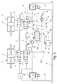
- the safety valve 21 is designed that the connection between the second line section 25 and the third line section 27 and between the fourth line section 33 and the fifth line section 35 is blocked.
- the magnetic device M1 of the safety valve 21 activated so that the control piston of the safety valve against the force of the Spring 37 is shifted to the right so that how indicated by arrows, a hydraulic connection between the line sections 25 and 27 as well 33 and 35.
- This hydraulic connection is set up continuously manufactured.
- control of the magnetic devices M1 and M2 takes place via a control device 41, which here is only hinted at.
- a pressure regulator 43 is in the hydraulic line 13 integrated, which acts as a proportional pressure relief valve is trained and through which in the Hydraulic line 13 prevailing pressure continuously is adjustable.
- the pressure regulator comprises a magnetic device M3 that against the one control line 45 pressure applied to a spool acts and with an adjustable overpressure hydraulic oil via a relief line 47 to the tank 15 issues.
- Figure 1 also shows a pressure sensor 49, the pressure generated by the pump 11 is detected.
- the sensor is an example here in the first line section 23 arranged. It is about one not shown here electrical line with the control device 41 connected to the output signals of the sensor detected and for controlling the valves, for example of the safety valve 21 is evaluated.
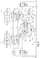
- the switching valve 19 When the switching valve 19 is activated, provided there is pressure on the hydraulic line 13 ' is, the second pressure chamber 31 'via the line section 23 ', the switching valve 19' and the Line section 33 'pressurized. At the same time, the first pressure chamber 29 'is above the Line section 27 ', the safety valve 21', the line section 25 'and via the changeover valve 19 'connected to the tank 15 and thus relieved of pressure. If, for example, the case arises, that the changeover valve 19 is in this position, So in its right end position, jammed and therefore would no longer be switchable, so that in the Pressure chamber 31 'and the line section 33' prevailing Pressure reduced via the pressure regulator 43 ' become.
- Figure 2 also shows that in the line section 23 ', as in the left part of the device 1' of the figure 2, a pressure sensor 49 'is provided, which via a line not shown here with the Control device 41 is connected.
- the hydraulic plan according to Figure 2 shows that the Hydraulic devices 3 and 3 'of the front and Rear axle from a single pump 11 with hydraulic fluid be supplied.
- a Current regulator 55 includes.
- the current regulator 55 is included a pressure relief valve called a pressure pilot 69 equipped with a control line 71 and a throttle 73 with the hydraulic line 13 and thus connected to the pressure outlet 59 of the pump 11 is.
- Print pilots of the type mentioned here are known. For example, they have a ball 75 on by a spring 77 against a valve seat 79 is pressed.
- the pump 11 With an overpressure that over is a value defined by the spring 77, lifts the ball 75 from the valve seat 79 so that oil can flow to the tank 15.
- the pump 11 is here provided with a suction throttle 57, which from the Tank 15 conveyed fluid flow on a predetermined Maximum value holds.
- the hydraulic line 13 is here via a throttle D1 connected to the pressure outlet 59 of the pump 11.
- a line section 61 leads directly from Pressure outlet 59 to the flow regulator 55, the control piston 63 on the one hand with the force of a spring 65 and the pressure prevailing in the control line 71 is applied, on the other hand via a control line 67 with the pressure given at the pressure outlet 59.
- the control piston 63 separates the line section 61 from the hydraulic line 13 ', which serves to supply the rear axle.
- the pump 11 preferably operates while driving in the regulation area, that is, it promotes a constant volume flow.
- the current regulator 55 preferably represents primarily the hydraulic device 3, i.e. the front axle, a constant volume flow to disposal.
- the pressure regulators 43 and 43 ' are designed so that a pressure of approx 0 bar to 200 bar is adjustable. This ensures that the one delivered to the front axle Pressure, that is also to the hydraulic device 3 is delivered, is at least equal or larger than that applied to the hydraulic device 3 ' Pressure that is provided for the rear axle.
- the hydraulic plan according to Figure 2 shows that the hydraulic device 3 of the front axle and the Hydraulic device 3 'of the rear axle separate Pressure regulators 43 and 43 'are associated with the hydraulic lines 13 and 13 'in Hydraulic connection and that of the control device 41 can be controlled and exceeded of the specified hydraulic oil pressure the relief lines 47 and / or 47 'to the tank 15 let out.
- the pressure regulators 43 and 43 ' are coupled here in such a way that if one of the pressure regulators fails, the other as a pressure relief valve for the entire system, also for the other hydraulic line serves.
- the device shown in Figure 2 1 ' is a coupling via the current dividing device 53 or via the current regulator 55 in Interaction with what is known as a pressure pilot Pressure relief valve 69 provided. How it works This coupling is the following:
- the first is Connection between the line section 61 and the hydraulic line 13 'of the rear axle the current regulator 55 or its piston 63 interrupted.
- the one provided by the pump Hydraulic oil is thus via the hydraulic line 13 supplied to the hydraulic device 3.
- the control piston 63 the hydraulic connection releases to the hydraulic line 13 '.
- the second pressure regulator 43 ' is supplied with oil.
- the two pressure regulators 43 and 43 ' are set so that the one provided for the front axle Pressure equal to or greater than that of the rear axle is.
- FIG. 2 The safety valves 21 and 21 'are like in the embodiment in Figure 1, in immediate Proximity to the hydraulic device 3 or 3 'arranged. Errors in the rest Components derived from the hydraulic plans of the figures 1 and 2 can be seen and to undefined states can lead from the safety valve 21st or 21 'are intercepted. Through the Safety valves 21, 21 'is therefore a fail-safe function given.
- Such a throttle is indicated in Figure 2 and provided with the reference symbol D2.
- the the stabilizer sections assigned to the hydraulic device 3 ' are not rigid with each other coupled, but also not completely decoupled. So there can still be torques from a stabilizer section via the hydraulic device 3 ' be transferred to the other stabilizer section, so that a residual function of the anti-roll bar is guaranteed. However, are no longer active Torques in the anti-roll bar, respectively introduced in its sections. A complete Decoupling of the anti-roll bar is possible by eliminating throttle D2.
- This decoupled version of the two valves is also provided on the valve device 17 according to FIG. 2.
- the safety valves are also there 21 and 21 'with each other and the switching valves 19th and 19 'rigidly coupled to one another.
- the device 1 ' according to Figure 2 is characterized in rest in that the current divider 53 through the current regulator equipped with a pressure pilot shows low vibration and tolerance problems. This in turn makes a huge contribution to security the facility shown here. After all, those are the rear and front axles associated pressure regulator 43 and 43 'coupled so that if one of the pressure regulators fails the other still against the entire system in the event of a fault can protect too high a pressure.
- the device 1 ' is a hydraulic line 110 provided, which has a valve unit 112.
- the hydraulic line 110 is used to produce a hydraulic connection between the Hydraulic devices 3 and 3 'provided Pressure levels.
- the hydraulic line 110 bridges that is, the current dividing device 53 Hydraulic line 110 here with the hydraulic devices 3 and 3 'with an oil flow Hydraulic lines 13 and 13 'connected, in which the same pressure level prevails as in them respectively assigned pressure regulators 43 and 43 '.
- Valve unit 112 is preferred designed as a mechanical check valve that a valve seat 114 into which a ball 116 is pressed is included. Such valve units are simple constructed and functional.
- the valve unit 112 connects the pressure levels of the two Hydraulic devices 3, 3 'preferably always then when the applied to the hydraulic device 3 Pressure is less than that at the hydraulic device 3 'applied pressure.
- the valve unit 112 connects the pressure levels of the two Hydraulic devices 3, 3 'preferably always then when the applied to the hydraulic device 3 Pressure is less than that at the hydraulic device 3 'applied pressure.
- Valve unit balancing the manufacturing and Setting tolerances of the individual assemblies, for example the pressure regulator 43, 43 ', the pump 11 and the current dividing device, which is possible influence the pressure levels. Further are improperly made and not wanted Settings of the pressure regulator by the Fluid connection compensated.
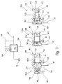
- FIG 3 is a schematic diagram of a changeover valve reproduced together with the hydraulic symbol.
- the hydraulic one Symbol including a first functional position of the changeover valve and a second one at the very bottom Functional position of the switch valve shown.
- Figure 3 is that shown in Figure 2 Valve device with the switching valves 19 and 19 'shown.
- the two sub-valves to represent the Function shown separately, being here rigidly coupled to one another via a rod 81 are.
- the control pistons of both valves advantageously to a control piston 83 summarized in a cylindrical bore 85 is guided against the force of a spring 87.
- the Spring counteracts a magnetic device M2.
- In the wall of the bore 85 are different grooves introduced, which are provided here with numbers that the inputs and outputs of the switching valves 19 and 19 'correspond.
- the top ports of the switch valve 19 are with 1 and 3, that of the changeover valve 19 'marked with 4 and 6.
- the lower Connections of the switching valve 19 are with the Tank symbol and the number 2, that of the changeover valve 19 'also with the tank symbol and the number 5 marked.
- the control piston is located in the upper illustration 83 in inactive state. That is, the magnetic device M2 is not activated, so the Spring 87 move the spool 83 to the left can.
- the control piston is provided with control surfaces, which are delimited by control edges and -in Dependence on the position of the control piston the ring grooves 91 serving as feed and discharge accordingly separate from each other or with each other connect.
- connection 3 is inside the changeover valve 19 connected to the tank; are connections 1 and 2 interconnected. Within the changeover valve 19 ', the connection 6 is connected to the tank and the connections 5 and 4 are interconnected. This is shown in the hydraulic symbol above in Figure 3 indicated by the crossed arrows. It is thus ensured that the connections of the two pressure chambers 29 and 31 and 29 ' and 31 'are interchanged when the changeover valve appeals. This will be opposite Moments through the hydraulic devices 3 or 3 'in the associated stabilizer sections initiated.
- Detection device 90 may be provided which Slider stroke determined.
- the exemplary embodiment is the detection device in the area of bore 85, at its right end, arranged. At the right end of hole 85 is the tank pressure. The maximum distance that the The control piston can be replaced is marked with a Y.
- the magnetic device is activated M2
- the control piston 83 is shifted to the right.
- the distance traveled or the current position of the control piston is via a suitable sensors, for example a piezo sensor, determined.
- the current To determine the switching position of the control piston arranged inaccessible from the outside within a housing is.
- the control piston position can be, for example Control spool terminals detected and displayed become.
- the detection device 90 transmits this in the form of an electrical signal, for example to the control device 41, which after actuation of the solenoid valve assumes that the control piston is in its tax position. This improves operational safety in particular of devices 1 and 1 '.
- FIG. 4 shows the safety valves 21 and 21 ', which are shown in Figure 2.
- a rod 92 is also located here in both sub-valves provided a rigid coupling of the two Control piston causes.
- Such a safety valve is implemented advantageously such as in the two lower ones Representations according to Figure 4 can be seen. It becomes a continuous piston 93 in a cylindrical Hole 95 housed in the wall Ring grooves 97 are introduced, which are not with here shown hydraulic connections interact.
- the piston 93 has control collars and control edges through which the ring grooves in different Way to be connected can.
- the ring grooves 97 are the connections of the safety valves assigned, marked here with digits are.
- the safety valve 21 has two upper connections 2 and 4 and two lower connections 1 and 3 on while the safety valve 21 'an upper connection 6 and two lower connections 5 and 7, the connection 7 with is connected to the tank, which is shown here by the tank symbol is made clear.
- the safety valve here has a magnetic device M1, which acts on the piston 93, the when activating the magnetic device M1 against the Force of a spring 99 is shifted to the right.
- the piston 93 In the top sketch is the piston 93 in his shown inactivated position. This means, the magnetic device M1 is without current, so that the Spring 99 can push the piston 93 to the left.
- this functional position is as from the schematic diagram recognizable according to Figure 4, a hydraulic Separation of connections 1 and 2 as well as connections 3 and 4 given as in the safety valve 21 is shown. At the same time is one hydraulic separation between the connections 6 and 5, on the other hand a hydraulic connection given between connections 7 and 6.
- FIG. 5 shows a hydraulic plan of an embodiment variant the device 1 'for reduction the roll tendency for a vehicle with two axles. Parts which correspond to those in FIG. 2, are provided with the same reference numerals, so that insofar referred to the description of FIG. 2 becomes. The following is just the differences received.
- the hydraulic plan according to figure 5 shows a current dividing device 53a, the one Current regulator 55a includes that in the fluid path between the pump 11 and that assigned to the rear axle Hydraulic device 3 'is arranged.
- the current regulator 55a is via a hydraulic line 118, a serving as hydraulic resistance nozzle DÜ1 and a line section 120 with the pressure outlet 59 the pump 11 and via a line section 122 with the supplying the hydraulic device 3 ' Hydraulic line 13 'connected.
- the one in the unpressurized State of the pump 11 shown current regulator 55a has a control piston 63, on the two There is pressure on each end.
- the one Front of the control piston 63 is with a Pressure applied in the flow direction of the Considered fluids - behind the nozzle DÜ1 at the Hydraulic line 118 is tapped.
- the other Front side of the control piston 63 is via control lines 126 and 128 with the hydraulic line 13, the the hydraulic device assigned to the front axle 3 supplied with pressurized hydraulic oil, connected.
- the hydraulic line 13 is again via a nozzle DÜ2 and a line section 130 with the pressure outlet 59 of the pump 11 connected. If the pump 11 is started up, so they are on the front of the control piston 63 applied pressures by means of the control piston 63 compared with each other. Is that in the control line 124 prevailing pressure greater than that in the Control line 126 applied pressure, so the Control piston 63 shifted to the right. Through the Shifting the control piston 63 to the right a fluid connection from the pressure outlet 59 of the pump 11 released to the hydraulic line 13 '.
- the hydraulic line 13 is from the current regulator 55a uncoupled and is constantly filled with hydraulic oil provided. Is the pressure in the control line 126 larger than in the control line 124, the Control piston 63 to the left in its control position shifted and the flow connection from the pressure outlet 59 interrupted to the hydraulic line 13 '.
- the pressure in the hydraulic lines 13 and in the leading to the rear axle, after the nozzle DÜ1 Section of hydraulic line 118 is near same size. Now is the pressure drop at one determined volume flow after the nozzle DÜ2 larger than after the nozzle DÜ1, the current regulator 55a actuated such that a larger fluid flow for Rear axle and a smaller fluid flow to the front axle flows. In the opposite case, so if the pressure after the nozzle DÜ2 is greater than that Pressure after the nozzle DÜ1, the control piston of the Current controller 55a operated so that the front axle associated hydraulic device 3 with is supplied with a larger fluid flow than that of the Hydraulic device 3 'assigned to the rear axle.
- the pressure drop in the area of the nozzles and thus that Distribution ratio of the fluid flows is above that Resistance of the individual nozzles adjustable. Poses a pressure in the operation of the device 1 ' Hydraulic line 13 ', which is larger than that in the hydraulic line 13, the current regulator opens 55a and the division of the fluid flows only takes place still depending on the nozzle cross sections and the Press the front and rear axles. In this case the fluid flow becomes the front axle, i.e. the Hydraulic line 13, in deviation from the control volume flow increased and the more the rear axle pressure, thus the pressure in the hydraulic line 13 ', exceeds the front axle pressure. This will create a improved dynamics on the front axle that helps to get the system back to normal offset.
- the right end of the control piston 63 of the Current regulator 55a can, in addition to that via the control line 126 applied compressive forces, in addition of a spring force applied by a spring 65 indicated by dashed lines is applied.
- the spring 65 presses in that shown in Figure 5 Embodiment of the device 1 'the control piston 63 to the left in the direction of its control position, whereby the control piston 63 only its control position leaves and opens fully when the Pressure behind nozzle DÜ1 is greater than that of the spring 65 and that of the control line 126 prevailing pressure applied to the right face becomes.
- the spring 65 can also be on the opposite End face of the control piston 63 is arranged be on the side where the control line 124 applies pressure to the control piston.
- the control piston leaves its Control position and completely opens the fluid path between the hydraulic line 118 and the line section 122 if the sum of the on the left end of the control piston acting Forces arising from the spring force and behind the Nozzle DÜ1 composed of the prevailing pressure, larger is than that on the right face of the spool acting pressure forces behind the nozzle DÜ2 can be tapped. If the spool is its Leave the control position and the fluid path between the hydraulic line 118 and the hydraulic line 13 'has opened completely, the division takes place of the fluid flow delivered by the pump only still depending on the nozzle cross sections and the pressures acting on the front and rear axles.
- a pressure pilot Pressure relief valve 69 may be provided via a control line 132, via the control line 128, from which the control line 126 branches, and a nozzle DÜD, via the nozzle DÜ2 and the line section 130 with the pressure outlet 59 of the pump 11 connected is.
- the pressure relief valve 69 is analogous to formed the pressure relief valve shown in Figure 2 and also has a ball 75 which pressed by a spring 77 against a valve seat 79 becomes.
- the front side of the control piston acts on the pressure that is tapped behind the nozzle DÜ1. Because of the low pressure drop, which - compared to greater pressure drop on the other side of the Control piston through the nozzles DÜ2 and DÜD- after the Setting nozzle DÜ1, the control piston 63 opens the Connection from line section 118 to line section 122.
- the pressure differential is preferred dimensioned such that the control piston in the open position moves so that only a small Oil quantity as control oil quantity through the pressure relief valve 69 drains into the tank while most of the by the pump 11 volume flow over the Flow current controller 55a to the hydraulic device 3 ' can.
- the pressure regulator 43 ' Take over the function of the pressure regulator 43.
- the current dividing device 53a can be one, for example as a mechanical one
- Check valve trained valve unit 112 may be provided, the connection between the hydraulic line 13 and the hydraulic line 13 'produces.
- the valve unit 112 prevents that the pressure in the hydraulic line 13 ' can be much larger than in the hydraulic line 13 of the front axle.
- the valve unit 112 has a ball 116 which is in a valve seat 114 is present.
- the ball 116 can - as dashed indicated by a spring in the valve seat 114 be pressed.
- the spring increases the allowable Pressure in the hydraulic line 13 '.
- the feather has in particular the advantage that, for example driving straight ahead, in the hydraulic lines 13 and 13 'a minimal and practical the valve unit has approximately the same pressure 112 does not respond permanently and vibrate begins, which leads to increased wear of the valve unit leads.
- the spring is preferably like this designed that the ball only from a defined Pressure difference is lifted from the valve seat.
- FIG. 5 also shows a throttle D3, which is arranged in the safety valve 21 and in deactivated state of the safety valve Connection between the two pressure chambers of the Hydraulic device 3 produces. So in this Switch position of the safety valve a damped Overflow of hydraulic oil from one Pressure chamber to another possible, which improves driving stability increased in the event of a malfunction.
- Figure 6 shows a hydraulic plan of another Design variant of the device 1 'to avoid the curl of a vehicle with at least two each having at least two wheels Axes.
- the device 1 'shown in FIG. 6 differs from that shown in FIG. 5 in that the valve unit 112 by a Pressure regulator 134 is replaced.
- a pressure regulator instead of a check valve prevents the pressure in the hydraulic line 13 'can be greater than the pressure in the hydraulic line 13.
- the pressure regulator is as so-called single-edge slide formed, that is only has a control edge or a seat and when actuated, that is, when relocated an outflow of the hydraulic oil from the Enable hydraulic line 13 'in the tank 15 can.
- pressure regulator 134 On the right side of pressure regulator 134 or on the slider of which is in the Hydraulic line 13 'prevailing pressure, which over a control line 136 is tapped. On the other, the left side of the pressure regulator 134 is via a control line 138 from the Hydraulic line 13 tapped pressure. It can as indicated, a spring 140 can be provided, either on both sides of the pressure regulator 134 can be arranged. In the shown in Figure 6 The embodiment is the spring 140 the right side of the pressure regulator 134 is arranged. This ensures that the pressure regulator 134 a fluid connection from the hydraulic line 13 'to tank 15 as soon as the pressure in the Hydraulic line 13 is smaller than the sum of Forces by spring 140 and that in the control line 136 applied pressure can be applied.
- the spring ensures, similar to spring 77 of the pressure relief valve 69 that the pressure regulator 134 does not respond constantly and the fluid connection opens and closes practically continuously, like it, for example, when driving straight ahead Motor vehicle may be possible. A swing of the Pressure regulator 134 can thus be practically excluded become.
- Figure 7 shows a hydraulic in the upper figure Symbol of the pressure regulator described for FIG. 6 134.
- the pressure regulator 134a has a control slide 142a, which in a bore 144 is movably mounted.
- a first one Pressure chamber 146 is between a wall 145 the housing of the pressure regulator and the left front side of the control spool 142a, in which the Control line 136 opens, the pressure on the Hydraulic line 13 'taps.
- a second pressure chamber 148 is limited, in which the pressure prevailing in the hydraulic line 13 ' the control line 138 is applied. Still is a hydraulic resistance W1 and W2, for example nozzles, in the control lines 136 and 138 arranged that of damping serve.
- the hydraulic line 13 ' opens into the bore 144 in an area where the spool has an incision.
- Position of the control spool 142a is the control spool in control position.
- Control spool 142a shifted to the right and gives a fluid connection from the hydraulic line 13 ' to tank 15 free.
- the control slide 142a is with a control surface provided by a control edge 149 is limited, which leads to the tank, in the hole 144 arranged annular groove from the Separates annular groove in which the hydraulic line 13 ' flows.
- the middle figure in Figure 7 shows another Design variant of the pressure regulator 134.
- the Pressure regulator 134b has a spool 142b in contrast to the control spool 142a Has incision.
- the hydraulic line 13 ' opens directly into the first pressure chamber 146 by the spool 142b respectively through the control edge 149 opposite the tank 15 is separated.
- the second pressure chamber 148 is via the hydraulic resistance W2 and via the Control line 138 connected to the hydraulic line 13.
- too Control spool a fluid connection from the hydraulic line 13 'to the tank 15 free when the on the right-hand end of the spool Forces are smaller than those on the left front side acting forces resulting from the force of Spring 140 and the forces of the hydraulic line 13 'prevailing pressure.
- FIG. 7 In the right figure of Figure 7 is another Pressure regulator 134c shown that a spool 142c, the end faces of which are different have large areas where the respectively created at the pressure rooms 146 and 148 Pressure works.
- the one facing the second pressure chamber 148 Front face 150 of the control slide has a smaller cross-sectional area on which the Can attack pressure forces than the first Front 152 facing pressure chamber 146.
- the pressure regulator 142c is designed such that he fluid connection from the first pressure chamber releases to the tank when the pressure in the hydraulic line 13 'is multiplied by a factor ⁇ 1 with the prevailing in the hydraulic line 13 Pressure minus that of the spring force Drucks.
- the front and rear axles are also available Can be precisely defined via the current divider device 53, 53a Volume flow available independently of the operating pressure of the pump. This one for The available volume flow determines the dynamics of the two hydraulic circuits and ensures its constancy for stable control behavior.
- Figure 8 shows a hydraulic plan of another Design variant of the device 1 'for reduction the curl of a vehicle with at least two having at least two wheels each Axis. Parts that match those in those previously described Figures match, have the same reference numerals provided so that in this respect to their description to the figures already described is referred.
- the current dividing device 53a points towards the current divider device shown in FIG the difference that here the Pressure regulator 43 ', the pressure in the hydraulic line 13 'limited to a defined value, and the pressure sensor 49 'are not required.
- the pressure regulator 134 is via the control line 138 directly with the hydraulic line 13 connected.
- the pressure regulator 134 On the opposite side of the Pressure regulator 134 is located via control line 136 the pressure prevailing in the hydraulic line 13 ' on, possibly by the force of a spring is supported.
- the pressure regulator can be like one the pressure regulator a, b or described for FIG c be formed.
- the control piston 63 of the current regulator 55a is pressurized to is tapped behind the nozzle DÜ1.
- the pressure in the control line 124 acts in the direction of the open position.
- On the other side of the spool a pressure acts on the control line 128 the hydraulic line 13 is tapped. This on the control piston 63 acting pressure forces are amplified by the spring 65 indicated here.
- Figure 9 shows a hydraulic diagram of another Implementation variant of the device 1 ', the from the device shown in FIG. 8 distinguishes that the current dividing device 53a additionally has the pressure relief valve 69, that over the control line 132 and over the Nozzle DÜD prevailing in the hydraulic line 13 Takes off pressure. Furthermore, this is due to the Pressure regulator 134 applies pressure to a control line 138 '-in the direction of flow of the hydraulic oil considered - is tapped behind the nozzle DÜD.
- the following is the function of the current dividing device explained in more detail according to FIG. 9:
- the pressure in the hydraulic line 13 'then turns accordingly the design of the pressure regulator 134 (cf. the design variants described in FIG. 7) in a certain ratio, for example with offset, that is, with a imbalance caused by the spring force the pressures in the hydraulic lines and control lines 138 'and 136, respectively the pressure in line 138 'by the action of the Pressure relief valve 69 is limited.
- the current dividing devices 53 according to the invention and 53a are preferred for reasons of driving stability pressure on the front axle Available as the rear axle.
- a current regulator 55a can be used, the only one control edge has that overlaps and closes or releases a fluid path.
- Such one Current regulator 55a is less sensitive to vibrations than a classic current divider, the two Has control edges, especially when the Approximate pressure on the front and rear axles is the same size.
- Single edge current regulator can also be a Classic current divider with two control edges used be ensured by end stops is that only one that the rear axle assigned control edge in overlap can drive and that the other control edge, the the Front axle is assigned, not completely can close. Through this measure, the Vibration sensitivity of the double-edge current divider reduced.
- the current regulators 55 and 55a differ in that that the current regulator 55 has a constant Volume flow to the front axle and only the rest of what is pumped Hydraulic oil reaches the rear axle, the two volume flows can be the same if the Pump delivers a constant volume flow while for the current regulator 55a, the distribution ratio remains constant.
- the current regulator 55a realizes that the volume flow delivered by the pump always divided with the same ratio is so that the hydraulic oil is constantly uniform, within the specified division ratio, to the front and rear axles respectively Hydraulic devices 3 and 3 'supplied becomes.
- FIG. 10 shows a basic circuit diagram of a sensor device 160, which has a slide 162, which is guided in a bore 164. Between one Wall 166 and the left face of the Slider 162 is delimited by a first chamber 168 and between the right end of the slide and the wall a second chamber 170.
- the first Chamber 168 is above a line section 172 for example with the fifth line section 35 (compare Figure 2) and the chamber 170 via a Line section 174 with the second line section 25 (see Figure 2) in connection.
- the sensor device 160 can be anywhere within the device 1 or 1 'to be arranged which a pressure difference is to be determined.
- the Slider 162 is supported by two springs 176 and 178 applied a force to its end faces, which the slide in a middle position - as in Figure 10 holds.
- the slide 162 points one at each of its end areas Pin 180 on, one each on the pin movably guided sealing washer 182 arranged is.
- the sealing washers 182 define the central position of the slider 162.
- the maximum distance, which the slider 162 can cover is with a X is marked by the length of the Cone defined.
- the left and right end positions of the slide 162 is through the pin 180 or determined by their length, that serve to limit the path. In the end positions of the Slider pushes one of the pins on the wall 166 of the housing.
- the wall 166 thus serves as a stop.
- the preferably in a stable middle position located slide can - in the shown in Figure 10 Embodiment - accordingly to the left and be shifted to the right by a distance X / 2. Due to the action of the spring 176 and 178 leaves the slide 162 the middle position only when the pressure present in one of the chambers around a certain one Amount is greater than the pressure in in the other chamber. That means that if the pressure in the first chamber 168, for example is greater than the pressure in the second chamber 170, the slider 162 is shifted to the right and vice versa.
- This shift will, for example by means of a wire 186, which in a in the slide 162 arranged annular groove 188 engages and deflects is grasped and by means of an only indicated here electrical or electronic detection device 184 converted into an electrical signal, for example to the control device 41 forwarded to the device 1 or 1 ' becomes.
- the sensor device 160 is generally applicable to two pressures together to compare.
- the sensor device can, for example the effect on the safety valve and / or check the changeover valve. Since the Shift and safety valves arranged within a housing are and from the outside the position of their Control piston is not visually recognizable, can Sensor device - as described - in a simpler manner Ascertain and if necessary directly Show.
- the positions of the slider 162 can for example, the individual directions of travel Be assigned to the motor vehicle. So it is conceivable that the middle position of the straight line, which at shifting the slider to the right Position of a right turn and the after moving the slide to the left assumed position assigned to a left turn is.
- the sensor device 160 can two instead of the slide 162 Pressure switches are provided which provide a signal forward to control device 41, for example, as soon as a preferably adjustable Threshold pressure in one of lines 172 and 174 is achieved.
- the pressure switches can each with a hydraulic line or a control line be connected. It is also conceivable that Pressure switch directly within a line, one Arrange chamber or a pressure room in which hydraulic oil under pressure.
- Figure 11 shows a block diagram of another Embodiment of the sensor device 160, which from the sensor device shown in FIG. 10 differs in that the sealing washers 182 and the spring 176 are omitted.
- This The preferred position or end position takes the Slider 162 both in the depressurized state and even if there is pressure in the first chamber 168 prevails that is smaller than the sum of those in the second chamber 170 applied pressure forces and pressure force generated by the spring 178.
- the spring 178 omitted and the spring 176 is provided so that the slide 162 in its right end position Has preferred position.
Landscapes
- Engineering & Computer Science (AREA)
- Mechanical Engineering (AREA)
- Vehicle Body Suspensions (AREA)
Applications Claiming Priority (5)
| Application Number | Priority Date | Filing Date | Title |
|---|---|---|---|
| DE19628612 | 1996-07-16 | ||
| DE19628612 | 1996-07-16 | ||
| DE19629582A DE19629582A1 (de) | 1996-07-16 | 1996-07-23 | Einrichtung zur Rollstabilisierung eines Fahrzeugs |
| DE19629582 | 1996-07-23 | ||
| PCT/EP1997/003761 WO1998002322A1 (de) | 1996-07-16 | 1997-07-14 | Einrichtung zur rollstabilisierung eines fahrzeugs |
Publications (2)
| Publication Number | Publication Date |
|---|---|
| EP0850151A1 EP0850151A1 (de) | 1998-07-01 |
| EP0850151B1 true EP0850151B1 (de) | 2001-10-31 |
Family
ID=26027559
Family Applications (1)
| Application Number | Title | Priority Date | Filing Date |
|---|---|---|---|
| EP97932827A Expired - Lifetime EP0850151B1 (de) | 1996-07-16 | 1997-07-14 | Einrichtung zur rollstabilisierung eines fahrzeugs |
Country Status (7)
| Country | Link |
|---|---|
| US (1) | US6039326A (ja) |
| EP (1) | EP0850151B1 (ja) |
| JP (1) | JP4146899B2 (ja) |
| AU (1) | AU3623597A (ja) |
| DE (2) | DE29619567U1 (ja) |
| GB (1) | GB2320472B (ja) |
| WO (1) | WO1998002322A1 (ja) |
Cited By (2)
| Publication number | Priority date | Publication date | Assignee | Title |
|---|---|---|---|---|
| EP1362721A2 (de) | 2002-05-16 | 2003-11-19 | Bayerische Motoren Werke Aktiengesellschaft | Regelsystem für ein Kraftfahrzeug mit Wankstabilisierung |
| WO2006105753A1 (de) * | 2005-04-07 | 2006-10-12 | Luk Lamellen Und Kupplungsbau Beteiligungs Kg | Einrichtung zur aktiven wankstabilisierung |
Families Citing this family (27)
| Publication number | Priority date | Publication date | Assignee | Title |
|---|---|---|---|---|
| DE19826747A1 (de) * | 1997-07-14 | 1999-01-21 | Luk Getriebe Systeme Gmbh | Getriebe |
| DE19846394C1 (de) | 1998-10-08 | 2000-03-09 | Bayerische Motoren Werke Ag | Stabilisierungseinrichtung für ein Fahrzeug |
| US6408676B1 (en) * | 1999-03-31 | 2002-06-25 | Caterpillar Inc. | Method and apparatus for determining the status of a relief valve |
| DE10009918A1 (de) * | 2000-03-01 | 2001-09-06 | Bayerische Motoren Werke Ag | Hydraulisches Stabilisierungssystem |
| US6538411B1 (en) * | 2000-10-13 | 2003-03-25 | Deka Products Limited Partnership | Deceleration control of a personal transporter |
| DE10210306A1 (de) | 2002-03-08 | 2003-09-18 | Volkswagen Ag | Anordnung zur aktiven Rollstabilisierung eines Kraftfahrzeugs |
| GB2388086B (en) * | 2002-05-02 | 2005-06-15 | Delphi Tech Inc | Vehicle roll control system |
| JP2004136814A (ja) | 2002-10-18 | 2004-05-13 | Kayaba Ind Co Ltd | 捩り剛性力制御装置 |
| DE50310382D1 (de) * | 2002-10-25 | 2008-10-02 | Schaeffler Kg | Wankstabilisator für das fahrwerk eines kraftfahrzeugs |
| GB0226843D0 (en) * | 2002-11-16 | 2002-12-24 | Cnh Uk Ltd | cab support system for an agricultural vehicle |
| WO2004085178A1 (de) * | 2003-03-26 | 2004-10-07 | Luk Fahrzeug-Hydraulik Gmbh & Co. Kg | Anti-wank-system |
| GB0410355D0 (en) * | 2004-05-10 | 2004-06-09 | Delphi Tech Inc | Vehicle roll control system |
| DE102004030009A1 (de) * | 2004-06-22 | 2006-01-12 | Hydac Electronic Gmbh | Hydraulische Steuervorrichtung |
| DE102005009002B4 (de) | 2005-02-28 | 2018-10-31 | Volkswagen Ag | Verfahren zum Betrieb von aktiven Stabilisatoren an Kraftfahrzeugen |
| DE102006002983B4 (de) * | 2006-01-21 | 2016-09-15 | Bayerische Motoren Werke Aktiengesellschaft | Aktives Fahrwerksystem eines Fahrzeugs |
| DE102006009524A1 (de) * | 2006-02-28 | 2007-09-06 | Pnp Automotive Gmbh | Stabilisator für ein Kraftfahrzeug |
| EP1862338A1 (en) * | 2006-05-29 | 2007-12-05 | Nederlandse Organisatie voor Toegepast-Natuuurwetenschappelijk Onderzoek TNO | Suspension system for a vehicle |
| DE112008000624T5 (de) * | 2007-03-23 | 2010-01-28 | ArvinMeritor Technology, LLC, Troy | Rollregelungeinrichtungen |
| US7717437B2 (en) * | 2007-05-08 | 2010-05-18 | American Axle & Manufacturing, Inc. | Actuator for disconnectable stabilizer bar system |
| US7722055B2 (en) * | 2007-06-18 | 2010-05-25 | Arvinmeritor Technology, Llc | Failsafe valve for active roll control |
| GB0714102D0 (en) * | 2007-07-19 | 2007-08-29 | Delphi Tech Inc | Vehicle roll control |
| GB2454013B (en) * | 2007-10-26 | 2009-12-30 | Lotus Car | A land vehicle suspension system |
| DE102008004913A1 (de) * | 2008-01-18 | 2009-07-23 | Conti Temic Microelectronic Gmbh | Hydraulische Absicherung einer Wankstabilisierung |
| US7887072B2 (en) * | 2008-10-09 | 2011-02-15 | American Axle & Manufacturing, Inc. | Stabilizer bar with disconnectable link |
| DE102010060251B4 (de) * | 2010-10-29 | 2017-08-24 | Ford Global Technologies, Llc. | Radaufhängung für ein Kraftfahrzeug |
| CN109070787B (zh) | 2018-04-11 | 2022-10-18 | 株式会社小松制作所 | 作业车辆 |
| EP4067127A1 (en) * | 2021-03-31 | 2022-10-05 | BeijingWest Industries Co. Ltd. | Suspension hydraulic lift actuator for axle trim height control |
Family Cites Families (19)
| Publication number | Priority date | Publication date | Assignee | Title |
|---|---|---|---|---|
| FR2048203A5 (ja) * | 1969-06-19 | 1971-03-19 | Besancenot Serge | |
| DE1962296A1 (de) * | 1969-12-12 | 1971-06-16 | Koppers Gmbh Heinrich | Pruefeinrichtung fuer Schuetzsteuerungen von zentral gesteuerten Transportanlagen |
| JPH0717136B2 (ja) * | 1986-10-13 | 1995-03-01 | 日本電装株式会社 | 油圧スタビライザ制御装置 |
| JPH0694253B2 (ja) * | 1986-03-17 | 1994-11-24 | トヨタ自動車株式会社 | 車輌用ロ−ル制御装置 |
| JPH0717137B2 (ja) * | 1986-10-16 | 1995-03-01 | 日本電装株式会社 | 油圧スタビライザ制御装置 |
| JP2606693B2 (ja) * | 1986-11-26 | 1997-05-07 | 呉羽化学工業株式会社 | ポリフエニレンスルフイドフイルムの縦延伸方法および装置 |
| JPS63188512A (ja) * | 1987-01-29 | 1988-08-04 | Nippon Denso Co Ltd | 車両用姿勢制御装置 |
| NL8702468A (nl) * | 1987-10-15 | 1989-05-01 | Volvo Car Bv | Voertuigwielophanging met rolcompensatie. |
| GB2235168A (en) * | 1989-08-24 | 1991-02-27 | Gkn Technology Ltd | A vehicle suspension system having an adjustable anti-roll bar |
| US5104143A (en) * | 1989-09-27 | 1992-04-14 | Toyota Jidosha Kabushiki Kaisha | Vehicle suspension system with roll control variable according to vehicle speed |
| FR2675435B1 (fr) * | 1991-04-22 | 1995-02-10 | Renault | Procede et installation de regulation des moyens antiroulis d'un vehicule. |
| DE9205781U1 (ja) * | 1992-04-29 | 1992-06-17 | Siemens Ag, 8000 Muenchen, De | |
| DE4326447A1 (de) * | 1993-08-06 | 1995-02-09 | Rexroth Mannesmann Gmbh | Hydraulikventil für eine Stabilisatorsteuerung an einem Kraftfahrzeug |
| DE4327044A1 (de) * | 1993-08-12 | 1995-02-16 | Rexroth Mannesmann Gmbh | Hydraulische Stabilisatorsteuerung |
| DE4337765A1 (de) * | 1993-11-05 | 1995-05-11 | Fichtel & Sachs Ag | Zweikreishydrauliksystem für eine aktive Fahrwerksregelung zur Unterdrückung der Rollbewegung eines Kraftfahrzeuges |
| DE9407167U1 (de) * | 1994-04-29 | 1994-07-07 | Hemscheidt Fahrwerktech Gmbh | Hydropneumatisches Federungssystem mit Stabilisierung |
| US5642282A (en) * | 1995-03-10 | 1997-06-24 | Isuzu Motors Ltd. | Apparatus for controlling attitude of a road vehicle cab |
| DE19549385C2 (de) * | 1995-04-08 | 1997-04-30 | Fichtel & Sachs Ag | Zweikreishydrauliksystem für eine aktive Fahrwerksregelung |
| DE19622964A1 (de) * | 1996-06-07 | 1997-06-05 | Fichtel & Sachs Ag | Aktiver Wagenheber |
-
1996
- 1996-07-23 DE DE29619567U patent/DE29619567U1/de not_active Expired - Lifetime
-
1997
- 1997-07-14 DE DE19780637T patent/DE19780637D2/de not_active Expired - Lifetime
- 1997-07-14 WO PCT/EP1997/003761 patent/WO1998002322A1/de active IP Right Grant
- 1997-07-14 AU AU36235/97A patent/AU3623597A/en not_active Abandoned
- 1997-07-14 JP JP50561398A patent/JP4146899B2/ja not_active Expired - Fee Related
- 1997-07-14 EP EP97932827A patent/EP0850151B1/de not_active Expired - Lifetime
- 1997-07-14 US US09/043,048 patent/US6039326A/en not_active Expired - Lifetime
- 1997-07-14 GB GB9805217A patent/GB2320472B/en not_active Expired - Fee Related
Cited By (3)
| Publication number | Priority date | Publication date | Assignee | Title |
|---|---|---|---|---|
| EP1362721A2 (de) | 2002-05-16 | 2003-11-19 | Bayerische Motoren Werke Aktiengesellschaft | Regelsystem für ein Kraftfahrzeug mit Wankstabilisierung |
| WO2006105753A1 (de) * | 2005-04-07 | 2006-10-12 | Luk Lamellen Und Kupplungsbau Beteiligungs Kg | Einrichtung zur aktiven wankstabilisierung |
| US7552929B2 (en) | 2005-04-07 | 2009-06-30 | LuK Lamelten und Kupplungsbau Beteiligungs KG | Active roll stabilization apparatus |
Also Published As
| Publication number | Publication date |
|---|---|
| GB2320472B (en) | 2000-09-20 |
| JPH11512997A (ja) | 1999-11-09 |
| AU3623597A (en) | 1998-02-09 |
| WO1998002322A1 (de) | 1998-01-22 |
| GB2320472A (en) | 1998-06-24 |
| EP0850151A1 (de) | 1998-07-01 |
| DE29619567U1 (de) | 1997-01-23 |
| GB9805217D0 (en) | 1998-05-06 |
| US6039326A (en) | 2000-03-21 |
| JP4146899B2 (ja) | 2008-09-10 |
| DE19780637D2 (de) | 1998-07-23 |
Similar Documents
| Publication | Publication Date | Title |
|---|---|---|
| EP0850151B1 (de) | Einrichtung zur rollstabilisierung eines fahrzeugs | |
| EP1175307B1 (de) | Hydraulisches stabilisierungssystem | |
| EP1609636B1 (de) | Hydraulische Steuervorrichtung | |
| DE3938417C1 (ja) | ||
| DE19646500C2 (de) | Einrichtung zur Rollstabilisierung eines Fahrzeugs | |
| DE102006012173A1 (de) | Fahrwerksystem | |
| DE102006046854B4 (de) | Hydrostatische Verstelleinheit mit einem Servosystem und einer das Servosystem steuernden Ventileinheit | |
| DE3300662A1 (de) | Niveauregeleinrichtung fuer fahrzeuge | |
| EP1342597B2 (de) | Anordnung zur aktiven Rollstabilisierung eines Kraftfahrzeugs | |
| EP3464908B1 (de) | Ventilvorrichtung | |
| DE10334705A1 (de) | Hydraulisches Fahrwerksystem | |
| DE102004027971B4 (de) | Hydraulische Lenkeinrichtung | |
| DE19629582A1 (de) | Einrichtung zur Rollstabilisierung eines Fahrzeugs | |
| DE4221088C2 (de) | Aufhängungssystem für Fahrzeuge | |
| EP2222965B1 (de) | Ventilvorrichtung | |
| EP3348430B1 (de) | Hydraulisches dämpfungssystem und gelenkfahrzeug mit einem derartigen dämpfungssystem | |
| DE112004000076B4 (de) | Anti-Wank-System | |
| WO2005021978A1 (de) | Hydraulisch gesteuertes ventil mit mindestens einem hydraulischen antrieb | |
| EP1542878B1 (de) | Hydraulische stabilisierungseinrichtung für fahrzeuge | |
| EP1526289B1 (de) | Ventil für Fluidsystem | |
| DE102004040940A1 (de) | Baugruppe für ein Fahrwerkstabilisierungssystem | |
| DE102021123114B3 (de) | Nockenwellenversteller mit Rückstellfunktion | |
| DE4435750C1 (de) | Steuervorrichtung für eine hydrostatische Maschine | |
| DE102012216630B4 (de) | Verstelleinrichtung für eine Axialkolbenmaschine undhydrostatischer Antrieb mit einer Axialkolbenmaschine mit einer Verstelleinrichtung | |
| EP0376023B1 (de) | Elektrohydraulisches Proportionalwegeventil |
Legal Events
| Date | Code | Title | Description |
|---|---|---|---|
| PUAI | Public reference made under article 153(3) epc to a published international application that has entered the european phase |
Free format text: ORIGINAL CODE: 0009012 |
|
| AK | Designated contracting states |
Kind code of ref document: A1 Designated state(s): FR IT |
|
| 17P | Request for examination filed |
Effective date: 19980722 |
|
| RBV | Designated contracting states (corrected) |
Designated state(s): FR IT |
|
| 17Q | First examination report despatched |
Effective date: 20000403 |
|
| REG | Reference to a national code |
Ref country code: DE Ref legal event code: 8566 |
|
| GRAG | Despatch of communication of intention to grant |
Free format text: ORIGINAL CODE: EPIDOS AGRA |
|
| GRAG | Despatch of communication of intention to grant |
Free format text: ORIGINAL CODE: EPIDOS AGRA |
|
| GRAH | Despatch of communication of intention to grant a patent |
Free format text: ORIGINAL CODE: EPIDOS IGRA |
|
| RAP1 | Party data changed (applicant data changed or rights of an application transferred) |
Owner name: LUK FAHRZEUG-HYDRAULIK GMBH & CO. KG |
|
| GRAH | Despatch of communication of intention to grant a patent |
Free format text: ORIGINAL CODE: EPIDOS IGRA |
|
| GRAA | (expected) grant |
Free format text: ORIGINAL CODE: 0009210 |
|
| AK | Designated contracting states |
Kind code of ref document: B1 Designated state(s): FR IT |
|
| ET | Fr: translation filed | ||
| PLBE | No opposition filed within time limit |
Free format text: ORIGINAL CODE: 0009261 |
|
| STAA | Information on the status of an ep patent application or granted ep patent |
Free format text: STATUS: NO OPPOSITION FILED WITHIN TIME LIMIT |
|
| 26N | No opposition filed | ||
| PGFP | Annual fee paid to national office [announced via postgrant information from national office to epo] |
Ref country code: FR Payment date: 20140721 Year of fee payment: 18 |
|
| PGFP | Annual fee paid to national office [announced via postgrant information from national office to epo] |
Ref country code: IT Payment date: 20140729 Year of fee payment: 18 |
|
| PG25 | Lapsed in a contracting state [announced via postgrant information from national office to epo] |
Ref country code: IT Free format text: LAPSE BECAUSE OF NON-PAYMENT OF DUE FEES Effective date: 20150714 |
|
| REG | Reference to a national code |
Ref country code: FR Ref legal event code: ST Effective date: 20160331 |
|
| PG25 | Lapsed in a contracting state [announced via postgrant information from national office to epo] |
Ref country code: FR Free format text: LAPSE BECAUSE OF NON-PAYMENT OF DUE FEES Effective date: 20150731 |