EP0848182A2 - Einrichtung und Benutzung eines Stossdämpfers - Google Patents
Einrichtung und Benutzung eines Stossdämpfers Download PDFInfo
- Publication number
- EP0848182A2 EP0848182A2 EP97850156A EP97850156A EP0848182A2 EP 0848182 A2 EP0848182 A2 EP 0848182A2 EP 97850156 A EP97850156 A EP 97850156A EP 97850156 A EP97850156 A EP 97850156A EP 0848182 A2 EP0848182 A2 EP 0848182A2
- Authority
- EP
- European Patent Office
- Prior art keywords
- piston
- shock absorber
- passage
- elastic
- medium
- Prior art date
- Legal status (The legal status is an assumption and is not a legal conclusion. Google has not performed a legal analysis and makes no representation as to the accuracy of the status listed.)
- Granted
Links
Images


Classifications
-
- F—MECHANICAL ENGINEERING; LIGHTING; HEATING; WEAPONS; BLASTING
- F16—ENGINEERING ELEMENTS AND UNITS; GENERAL MEASURES FOR PRODUCING AND MAINTAINING EFFECTIVE FUNCTIONING OF MACHINES OR INSTALLATIONS; THERMAL INSULATION IN GENERAL
- F16F—SPRINGS; SHOCK-ABSORBERS; MEANS FOR DAMPING VIBRATION
- F16F9/00—Springs, vibration-dampers, shock-absorbers, or similarly-constructed movement-dampers using a fluid or the equivalent as damping medium
- F16F9/32—Details
- F16F9/34—Special valve constructions; Shape or construction of throttling passages
- F16F9/3415—Special valve constructions; Shape or construction of throttling passages characterised by comprising plastics, elastomeric or porous elements
-
- F—MECHANICAL ENGINEERING; LIGHTING; HEATING; WEAPONS; BLASTING
- F16—ENGINEERING ELEMENTS AND UNITS; GENERAL MEASURES FOR PRODUCING AND MAINTAINING EFFECTIVE FUNCTIONING OF MACHINES OR INSTALLATIONS; THERMAL INSULATION IN GENERAL
- F16F—SPRINGS; SHOCK-ABSORBERS; MEANS FOR DAMPING VIBRATION
- F16F9/00—Springs, vibration-dampers, shock-absorbers, or similarly-constructed movement-dampers using a fluid or the equivalent as damping medium
- F16F9/32—Details
- F16F9/50—Special means providing automatic damping adjustment, i.e. self-adjustment of damping by particular sliding movements of a valve element, other than flexions or displacement of valve discs; Special means providing self-adjustment of spring characteristics
- F16F9/512—Means responsive to load action, i.e. static load on the damper or dynamic fluid pressure changes in the damper, e.g. due to changes in velocity
Definitions
- the present invention relates to an arrangement for minimizing or eliminating the damping of the shock absorber, in shock absorbers for vehicle wheels, in the case of small wheel movements around a zero position in the force/movement travel curve of the shock absorber with the aid of an elastic, preferably annular member which is located in or associated with one or more first passages for the working medium of the shock absorber so that, in the case of said small wheel movements, it allows complete or partial medium flow through the respective first passage and, in the case of greater wheel movements, it prevents said medium flow.
- the invention also relates to use of an (or a number of) elastic member(s) located in one or more passages for the working medium of the shock absorber.
- the elastic member is displaceable between two end positions. When the elastic member is situated between said positions, passage of a first quantity of medium is allowed. In at least one end position, the quantity of medium allowed through is prevented or reduced.
- the circulation type in particular represents an advantageous implementation of the function performed using the elastic ring.
- means and instructions are indicated with regard to how the small essentially undamped movements are to be selected, as are advantageous distances between the function carried out by the respective elastic element and the function or functions of a respective other member, in the form of said shim valves, conical valves and fixed throttle(s) etc., which influences the medium during shock absorption.
- the first passage(s) with associated elastic members is (are) arranged in a piston which forms part of the shock absorber and is provided with one or more second passages and, arranged in or close to this/these, medium-influencing member(s) as above, or alternatively separate from said piston.
- the shock absorber may thus consist, for example, of a circulation absorber and in this case the first passage(s) with associated elastic members can be arranged in a gable part where the first passage or the first passages connect an inner volume contained in an inner cylinder to a gap between the inner and outer cylinders of the shock absorber and, with that, the volume on the other side of the piston.
- the distance between the elastic member and the respective medium-influencing member is selected according to certain prerequisites where a very great elimination of overshooting tendencies in the force/velocity curve is effected and, with that, increased grip for the wheel against the surface in question is ensured.
- the annular flange comprises one or more first passages which extend essentially in the longitudinal direction of the shock absorber, for example parallel or helically in relation to the longitudinal axis of the shock absorber.
- the first passages may be intersected by an annular hole, in which the elastic element in the form of an annular element, for example an O-ring, is located.
- the annular hole is delimited at its periphery by an inner surface of the inner cylinder of the shock absorber, the elastic element assuming a dual function in that it also serves as a sealing element between the inner cylinder and the gable part.
- the first passages or the first passage are/is arranged at the outer periphery of the piston where the piston has an annular hole which in its outer part is delimited by the peripheral sliding seal of the piston, which seal interacts with an inner wall of the shock absorber cylinder.
- the first passage(s) extend(s) in this connection essentially in the longitudinal direction of the shock absorber (vertically or helically in relation to the longitudinal axis of the shock absorber).
- the elastic ring In the case where the elastic ring is located in the piston, this can be arranged with one or more conical valves functioning in axially extending second hole(s) which is/are connected to transverse holes, via which second holes and transverse holes the working medium is guided between the lower and upper sides of the piston by means of the conical valve(s).
- the elastic ring In the case with the elastic ring located in the piston, the elastic ring is located in an annular hole in the inner parts of the piston body, that is to say those parts of the piston bearing against the piston rod.
- the annular hole is connected to at least two diametrically arranged passage parts which can be connected to the annular hole on either side of the elastic ring inserted into the annular hole. Said passage parts can preferably open into the second passages in the piston.
- a distance between the elastic ring and shim packets arranged on the piston is selected preferably to correspond to essentially half the piston height, or be smaller.
- the elastic ring is located in an annular hole situated outside the respective said throttle.
- a radius for the respective throttle is related to the radius of the elastic ring. The first-named radius can be selected to be for example between 4/5-3/4 of the radius of the elastic ring.
- the relation established between the radius of the elastic member and the radius of the respective second passage positioning in the piston is such that the first-named radius has a value which is 1/2-2/3 of the value of the first-named radius.
- optimum values are selected for the distance between the seal and the transverse passage and the second passage and also the distance between the transverse passage in the first passage and the lower parts of the shim packet.
- the section of the elastic member is of hexagonal shape, which is preferably horizontal seen in the longitudinal direction of the shock absorber.
- the elastic member is also arranged to give rise to essentially undamped wheel movements within the range 0.1-1.0 mm.
- the undamped wheel movements are preferably selected so as to lie within the range 0.3-0.6 mm, or more specifically between 0.4 and 0.5 mm.
- the use according to the invention is characterized in that the elastic member(s) is (are) used in order essentially to prevent the occurrence of standing wave(s) and/or pressure peak(s) in the medium.
- the invention By means of the invention, it is easy to choose between a shock absorber function which is optimized to a very great degree and simplified manufacturing-friendliness and service-friendliness of the shock absorber.
- the latter case finds application in particular in so-called circulation absorbers.
- Advantageous distances between the various medium-influencing members can be introduced, which prevents said overshooting in the force/velocity curve of the shock absorber. Overshooting which may arise as a result of resilience in the medium, inertia in the valves, friction etc. is thus prevented.
- the invention prevents, or essentially eliminates, the occurrence of pressure surges and/or standing waves in the medium.
- the built-in function(s) allow manufacturing to be carried out extremely cheaply.
- the invention can be used inter alia on shock absorbers which are sold by ⁇ hlins Racing in the open market.
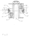
- a shock absorber is shown in a general manner with parts which are affected by the invention, a cylinder being shown by 1, a piston by 2 and a working medium, in which the piston works in the cylinder, by 3.
- the piston is fastened to a piston rod 4 which is provided with a bearing part 4a for the piston body which in this connection has a through-hole.
- the bearing part 4a is provided at its inner end with a thread 4b.
- shim packets 5 and 6 of known type are arranged on either side of the piston.
- the piston and the shim packets are fixed to the piston rod by means of a nut 7 which is screwed firmly on a thread 4b so that the shim packets and the piston body are pressed in the direction of a shoulder 4c, against which the lowest shim bears.
- the shims are provided with holes through which the piston rod part 4a extends.
- the piston 2a is provided with an inner wall 2b forming said hole, by means of which the piston bears against the piston rod part 4a.
- the piston body is provided with an annular hole 8, in which an elastic ring 9 is mounted slightly displaceably in the longitudinal direction R of the shock absorber.
- the hole 8 is connected to one or more first passages 10, 11 which open into or are connected to the cylinder spaces 1a, 1b on the upper and lower sides respectively of the piston.
- a first passage is shown in Figure 1 by passage parts 10 and 11 respectively, the first passage part 10 making a connection to the cylinder space 1b on the lower side of the piston and the second passage part making a connection to the cylinder space la on the upper side of the piston.
- the first passage(s) lead(s) through the hole 8, in addition to which the passage part 10 opens into the hole 8 on the lower side of the elastic ring and the passage part 11 opens into the hole 8 on the upper side of the elastic ring.
- the elastic member is pressed downwards (towards the space 1b) on compression and upwards (towards the space la) on expansion of the shock absorber.
- the arrangement is in this connection such that the elastic sealing ring moves in the longitudinal direction R during small initial wheel movements from or around an initial position for the shock absorber (see below).
- the piston is also provided with a second passage 12, 13 for leading the working medium 3 through the piston between the spaces la and 1b of the cylinder in a known manner.
- Said second passages may be parallel to the longitudinal axis of the shock absorber or have helical courses through the piston.
- the lower shim packet 6 operates on compression of the shock absorber and the upper shim packet 5 operates on expansion of the shock absorber.
- the first passage parts 10 and 11 open into the second holes 12 and 13 respectively. In this way, the hole 8 and the ring 9 can be given a position close to the piston centre (cf. longitudinal axis 14).
- an elastic ring can be given a radius rl which is roughly half the piston radius r2 or smaller.
- the radius r1 is 1/2-1/3 the piston radius r2.
- the shock absorber piston 4 has at its one end a holder 15, on which a symbolically shown wheel 16 is mounted directly or via a link (link mechanism).
- the mounting can take place in a manner known per se.
- small wheel or link movements for example movements of 0.1-1.0 mm around a zero position or initial position, the wheel remains essentially undamped or slightly progressively damped.
- said movement values are selected preferably within the range 0.2-0.6 mm, most preferably between 0.4 and 0.5 mm.
- a distance b between the innermost shim 5a and 6a respectively and the section centre 9a of the annular element/member is to have a value where the effect on the force and velocity curves (see below) of the shock absorber from inertia and friction of the medium-influencing members [lacuna]. Moreover, pressure surges and standing pressure waves can be eliminated or kept to a minimum.
- said value b is to be less than half the height bl of the piston or smaller.
- the shock absorber according to Figure 1 also has a fixing arrangement 17 for the shock absorber in the actual vehicle 18.
- the piston is in principle made with upper and lower parts assembled via a parting plane 19 in the transverse direction of the shock absorber.
- the piston is sealed against the inner wall 1c of the cylinder 1 via a piston seal 20.
- a distance between the lower shim 5a and the transverse part 11 of the first passage is indicated by c. This distance represents a proximity between the medium-influencing members 5 and 9 respectively. In the embodiment shown, this distance is less than the height of the section of the elastic member. More specifically, the height of the section in the longitudinal direction of the shock absorber according to Figure 1 is meant in this connection.
- the radius rl of the elastic element is less than a radius r2' for the respective second passage longitudinal axis. r1 is thus 1/2-3/4 of r2'.
- the shim packets are replaced by conical valves 21, 22 of a type known per se.
- the elastic annular member 9' has been assigned a position close to the periphery of the piston 2'.
- the first passage parts 10' and 11' have been assigned courses parallel to (are not L-shaped as in Figure 1) the longitudinal axis 14' of the shock absorber and are situated close to the periphery of the piston.
- Conical valves 21, 22 work with second passages 12', 13' which comprise passage parts 12", 13" extending in the transverse direction.
- a movement a' of the elastic sealing ring 9' corresponds to the wheel or link movement as above.
- the elastic member 9' in this case has a dual function in that it also seals against an internal surface on the piston seal 20'.
- An advantageous manufacturing method is characterized in this connection inter alia in that the elastic ring is located in its hole 8' and in that the piston seal 20' is subsequently applied to the periphery of the piston for interaction via its inside with the elastic member.
- a distance c' between the section centre of the sealing member 9' and the transverse hole 13' is indicated. Said distance is essentially the same size as or slightly greater than the height of the section in the longitudinal direction of the shock absorber.
- the invention also functions, according to Figure 3, in a piston 2' with one or more throttles 23.
- the throttles and the elastic member (the ring) 9" in this connection have their centres located on essentially the same cross-sectional plane 24.
- a radius r3 from the longitudinal axis 14'' of the shock absorber to the section centre of the seal 9" is greater than a radius r4 for the position of the throttle 23.
- the radius r4 is between 1/5-1/3, preferably 1/4, of the radius r3. In other respects, reference can be made to the above.
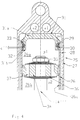
- the elastic member for example in the form of an elastic ring 29, in a hole 30 formed in or on a gable part 31.
- the gable part comprises an essentially circular plate-shaped or disc-shaped part 31a with a peripherally projecting flange 31b.
- the latter is provided with first passages 32 and 33 which connect the space 26a' of the cylinder above a piston 34 which according to the invention must be provided with medium-influencing members of some sort, that is to say in this case with shim packets 35, 36 on its upper and/or lower sides.
- the piston must also comprise one or more second passages 37 for guiding the medium between the upper and lower sides of the piston via the second passages and depending on the influence of the shim packets on the medium during compression and expansion movements of the shock absorber.
- Said first passage parts 32, 33 are preferably arranged parallel to the longitudinal axis 14''' of the shock absorber.
- the gable part 31a also includes valve arrangements V1 and V2 of a type known per se.
- Medium also passes between the upper and lower sides of the piston via the gap 28 in connection with said small movements a" (of the elastic ring or wheel/link in question respectively).
- the gap is connected to the lower side 26b of the piston.
- the flange 31b bears against the inner wall 26a of the inner cylinder 26.
- Figure 5 shows the case where the elastic member is located in a hole at the periphery of the piston and the elastic member seals against the inner surface of the piston seal (cf. the case according to Figure 2).
- the movement distance of the elastic member is indicated by a"'.
- the distance between the section centre of the elastic member and the lower shim packet is shown by b".
- the radius r4' is 1/2 to 2/3 the radius r3'.
- the embodiment according to Figure 5 thus draws its features from the embodiments according to Figures 1 and 3 with the difference that the elastic member according to Figure 1 is located closer to the centre, that is to say has a substantially smaller diameter than is the case in the embodiment according to Figure 3.
- a smaller elastic sealing ring results in more distinct movements.
- the differences between Figures 3 and 5 also concern the type of medium-influencing member (throttle instead of shim packet).
- Figure 6 shows the force and velocity curve/velocity curves for the shock absorber described above.
- the Y-axis represents the force axis F and the X-axis represents the velocity axis V.
- the diagram shows both positive and negative directions.
- the curve 38 rising in the positive direction can be given the shape shown in Figure 6 or given other shapes.
- the wheel movements are damped according to the case shown with the exponentially growing curve part 38.
- the curve part 38 becomes the curve part 38' for damping of the wheel movements via a small, gentle transition part 38".
- the overshooting tendency according to the curve part 38"' was in this way avoided.
- the aim is to obtain a direct transition between the curve parts 38 and 38'.
- the return of the curve according to a hysteresis function from a wheel deflection to the "0" position is indicated by 38"".
- the curve has the corresponding shape in the lower left quadrant according to Figure 6 and will therefore not be described here.
- Figure 7 shows different curves 39, 40 with the damping force F as a function of travel (X).
- the curve 39 is obtained for short strokes.
- the elastic member according to the invention thus causes the damping force to be a little (a lot) smaller in the case of small wheel movements (that is to say the short strokes) compared with the case of long strokes which are represented by the curve 40.
- the comparison is carried out at the respective fixed V max (cf. Figure 6).
- a short length of movement is shown by X'.
Applications Claiming Priority (2)
| Application Number | Priority Date | Filing Date | Title |
|---|---|---|---|
| SE9604548 | 1996-12-11 | ||
| SE9604548A SE508080C2 (sv) | 1996-12-11 | 1996-12-11 | Anordning och användning vid stötdämpare |
Publications (3)
| Publication Number | Publication Date |
|---|---|
| EP0848182A2 true EP0848182A2 (de) | 1998-06-17 |
| EP0848182A3 EP0848182A3 (de) | 2000-02-02 |
| EP0848182B1 EP0848182B1 (de) | 2003-11-05 |
Family
ID=20404930
Family Applications (1)
| Application Number | Title | Priority Date | Filing Date |
|---|---|---|---|
| EP97850156A Expired - Lifetime EP0848182B1 (de) | 1996-12-11 | 1997-11-10 | Einrichtung und Benutzung eines Stossdämpfers |
Country Status (5)
| Country | Link |
|---|---|
| US (1) | US6039159A (de) |
| EP (1) | EP0848182B1 (de) |
| JP (1) | JP3992805B2 (de) |
| DE (1) | DE69725954T2 (de) |
| SE (1) | SE508080C2 (de) |
Cited By (5)
| Publication number | Priority date | Publication date | Assignee | Title |
|---|---|---|---|---|
| EP1152166A1 (de) | 2000-05-04 | 2001-11-07 | Krupp Bilstein GmbH | Stossdämpfer mit amplitudenabhängiger Dämpfung |
| DE10047878B4 (de) * | 2000-05-04 | 2005-07-14 | Thyssenkrupp Bilstein Gmbh | Stossdämpfer mit amplitudenabhängiger Dämpfung |
| DE102004018990B3 (de) * | 2004-04-20 | 2005-11-17 | Thyssenkrupp Bilstein Gmbh | Stoßdämpfer mit amplitudenabhängiger Dämpfung |
| DE102004034057A1 (de) * | 2004-07-13 | 2006-02-09 | Zf Friedrichshafen Ag | Schwingungsdämpfer mit amplitudenabhängiger Dämpfkraft |
| EP1669632A1 (de) * | 2004-12-08 | 2006-06-14 | Zf Friedrichshafen Ag | Schwingungsdämpfer mit amplitudenselektiver Dämpfkraft |
Families Citing this family (5)
| Publication number | Priority date | Publication date | Assignee | Title |
|---|---|---|---|---|
| US6464053B1 (en) * | 1999-07-26 | 2002-10-15 | Tenneco Automotive Operating Company, Inc. | Single piece piston |
| DE10051971C1 (de) * | 2000-10-20 | 2002-03-28 | Krupp Bilstein Gmbh | Arbeitskolben für einen hydraulischen Stoßdämpfer und Verfahren zu seiner Hers tellung |
| JP4883708B2 (ja) * | 2006-11-21 | 2012-02-22 | カヤバ工業株式会社 | 緩衝器のバルブ構造 |
| DE102007013888A1 (de) * | 2007-03-20 | 2008-10-02 | Zf Friedrichshafen Ag | Schwingungsdämpfer mit amplitudenselektiver Dämpfkraft |
| DE102008002434B3 (de) * | 2008-06-16 | 2009-11-19 | Zf Friedrichshafen Ag | Schwingungsdämpfer mit amplitudenselektiver Dämpfkraft |
Family Cites Families (9)
| Publication number | Priority date | Publication date | Assignee | Title |
|---|---|---|---|---|
| FR962693A (de) * | 1950-06-16 | |||
| DE4110023A1 (de) * | 1991-03-27 | 1992-10-01 | Ringsdorff Werke Gmbh | Stossdaempferkolben aus ungleichen, gefuegten teilen |
| US3836132A (en) * | 1971-07-19 | 1974-09-17 | Maremont Corp | Self-leveling combined shock absorber and fluid spring assist unit |
| DE2323362A1 (de) * | 1973-05-09 | 1974-11-21 | Industrieanlagen Betriebsges | Daempfungsventil fuer hydraulische schwingungsdaempfer mit unterdrueckung der daempfung bei kleinen hueben |
| US4079925A (en) * | 1976-08-02 | 1978-03-21 | Atwood Vacuum Machine Company | Head end closure for the cylinder of a piston and cylinder assembly |
| JPS56120841A (en) * | 1980-02-27 | 1981-09-22 | Nissan Motor Co Ltd | Shock absorber |
| US5115892A (en) * | 1988-09-27 | 1992-05-26 | Atsugi Unisia Corporation | Hydraulic shock absorber with piston seal structure for enhancement of initial response |
| DE4002882C1 (en) * | 1989-08-12 | 1991-02-28 | Boge Ag, 5208 Eitorf, De | Hydraulic shock absorber with damping liq. contg. cylinder - has several passages and couplers, each on different partial diameters |
| US5697477A (en) * | 1994-10-07 | 1997-12-16 | Nifco Inc. | Air damper |
-
1996
- 1996-12-11 SE SE9604548A patent/SE508080C2/sv not_active IP Right Cessation
-
1997
- 1997-11-10 DE DE69725954T patent/DE69725954T2/de not_active Expired - Fee Related
- 1997-11-10 EP EP97850156A patent/EP0848182B1/de not_active Expired - Lifetime
- 1997-12-10 JP JP33975297A patent/JP3992805B2/ja not_active Expired - Lifetime
- 1997-12-11 US US08/988,662 patent/US6039159A/en not_active Expired - Lifetime
Non-Patent Citations (1)
| Title |
|---|
| None |
Cited By (8)
| Publication number | Priority date | Publication date | Assignee | Title |
|---|---|---|---|---|
| EP1152166A1 (de) | 2000-05-04 | 2001-11-07 | Krupp Bilstein GmbH | Stossdämpfer mit amplitudenabhängiger Dämpfung |
| DE10047878B4 (de) * | 2000-05-04 | 2005-07-14 | Thyssenkrupp Bilstein Gmbh | Stossdämpfer mit amplitudenabhängiger Dämpfung |
| DE10047878C5 (de) * | 2000-05-04 | 2009-07-16 | Thyssenkrupp Bilstein Suspension Gmbh | Stossdämpfer mit amplitudenabhängiger Dämpfung |
| DE102004018990B3 (de) * | 2004-04-20 | 2005-11-17 | Thyssenkrupp Bilstein Gmbh | Stoßdämpfer mit amplitudenabhängiger Dämpfung |
| DE102004034057A1 (de) * | 2004-07-13 | 2006-02-09 | Zf Friedrichshafen Ag | Schwingungsdämpfer mit amplitudenabhängiger Dämpfkraft |
| DE102004034057B4 (de) * | 2004-07-13 | 2006-04-20 | Zf Friedrichshafen Ag | Schwingungsdämpfer mit amplitudenabhängiger Dämpfkraft |
| EP1669632A1 (de) * | 2004-12-08 | 2006-06-14 | Zf Friedrichshafen Ag | Schwingungsdämpfer mit amplitudenselektiver Dämpfkraft |
| US7523818B2 (en) | 2004-12-08 | 2009-04-28 | Zf Friedrichshafen Ag | Vibration damper with amplitude-selective damping force |
Also Published As
| Publication number | Publication date |
|---|---|
| DE69725954D1 (de) | 2003-12-11 |
| SE9604548L (sv) | 1998-06-12 |
| DE69725954T2 (de) | 2004-09-09 |
| US6039159A (en) | 2000-03-21 |
| SE508080C2 (sv) | 1998-08-24 |
| SE9604548D0 (sv) | 1996-12-11 |
| JPH10184764A (ja) | 1998-07-14 |
| EP0848182A3 (de) | 2000-02-02 |
| JP3992805B2 (ja) | 2007-10-17 |
| EP0848182B1 (de) | 2003-11-05 |
Similar Documents
| Publication | Publication Date | Title |
|---|---|---|
| US6464053B1 (en) | Single piece piston | |
| US5024301A (en) | Hydraulic rebound stop assembly for a shock absorber | |
| US7703586B2 (en) | Four-piece piston | |
| US6371264B1 (en) | Fulcrum blow off valve for use in a shock absorber | |
| US6352145B1 (en) | Stroke dependent damping | |
| US5649611A (en) | Damping force control type hydraulic shock absorber | |
| US20040163905A1 (en) | Position-sensitive shock absorber | |
| CN103620257B (zh) | 低噪音阀组件 | |
| EP0848182A2 (de) | Einrichtung und Benutzung eines Stossdämpfers | |
| CN104603495B (zh) | 多级可调谐递减阀 | |
| US20010009214A1 (en) | Hydraulic damper for suspension systems | |
| EP1110768B1 (de) | Fahrzeugaufhängungsvorrichtung | |
| US6230858B1 (en) | Internally slotted orifice disc for low speed control in automotive dampers | |
| EP0122532B1 (de) | Stossdämpfer | |
| US4331224A (en) | Hydraulic shock absorber for vehicles | |
| US6668987B2 (en) | Shock absorber | |
| JPH0442595Y2 (de) | ||
| GB2092707A (en) | Telescopic hydraulic shock absorber with hydraulic rebound stop | |
| KR100443881B1 (ko) | 쇽업소버의 로드가이드 | |
| US20120138400A1 (en) | Shock absorber for a transportation means | |
| JPS5926817B2 (ja) | 車輛用緩衝器 | |
| CN113108005B (zh) | 一种减振器总成 | |
| JP3151751B2 (ja) | 減衰力調整式油圧緩衝器のピストン | |
| JPS6120340Y2 (de) | ||
| JPH0134769Y2 (de) |
Legal Events
| Date | Code | Title | Description |
|---|---|---|---|
| PUAI | Public reference made under article 153(3) epc to a published international application that has entered the european phase |
Free format text: ORIGINAL CODE: 0009012 |
|
| AK | Designated contracting states |
Kind code of ref document: A2 Designated state(s): DE FR GB IT NL |
|
| AX | Request for extension of the european patent |
Free format text: AL;LT;LV;MK;RO;SI |
|
| PUAL | Search report despatched |
Free format text: ORIGINAL CODE: 0009013 |
|
| AK | Designated contracting states |
Kind code of ref document: A3 Designated state(s): AT BE CH DE DK ES FI FR GB GR IE IT LI LU MC NL PT SE |
|
| AX | Request for extension of the european patent |
Free format text: AL;LT;LV;MK;RO;SI |
|
| 17P | Request for examination filed |
Effective date: 20000418 |
|
| AKX | Designation fees paid |
Free format text: DE FR GB IT NL |
|
| 17Q | First examination report despatched |
Effective date: 20011207 |
|
| GRAH | Despatch of communication of intention to grant a patent |
Free format text: ORIGINAL CODE: EPIDOS IGRA |
|
| GRAS | Grant fee paid |
Free format text: ORIGINAL CODE: EPIDOSNIGR3 |
|
| GRAA | (expected) grant |
Free format text: ORIGINAL CODE: 0009210 |
|
| AK | Designated contracting states |
Kind code of ref document: B1 Designated state(s): DE FR GB IT NL |
|
| REG | Reference to a national code |
Ref country code: GB Ref legal event code: FG4D |
|
| REF | Corresponds to: |
Ref document number: 69725954 Country of ref document: DE Date of ref document: 20031211 Kind code of ref document: P |
|
| ET | Fr: translation filed | ||
| PGFP | Annual fee paid to national office [announced via postgrant information from national office to epo] |
Ref country code: FR Payment date: 20040909 Year of fee payment: 8 |
|
| PLBE | No opposition filed within time limit |
Free format text: ORIGINAL CODE: 0009261 |
|
| STAA | Information on the status of an ep patent application or granted ep patent |
Free format text: STATUS: NO OPPOSITION FILED WITHIN TIME LIMIT |
|
| 26N | No opposition filed |
Effective date: 20040806 |
|
| PGFP | Annual fee paid to national office [announced via postgrant information from national office to epo] |
Ref country code: GB Payment date: 20041110 Year of fee payment: 8 |
|
| PGFP | Annual fee paid to national office [announced via postgrant information from national office to epo] |
Ref country code: DE Payment date: 20050124 Year of fee payment: 8 |
|
| PG25 | Lapsed in a contracting state [announced via postgrant information from national office to epo] |
Ref country code: GB Free format text: LAPSE BECAUSE OF NON-PAYMENT OF DUE FEES Effective date: 20051110 |
|
| PG25 | Lapsed in a contracting state [announced via postgrant information from national office to epo] |
Ref country code: DE Free format text: LAPSE BECAUSE OF NON-PAYMENT OF DUE FEES Effective date: 20060601 |
|
| GBPC | Gb: european patent ceased through non-payment of renewal fee |
Effective date: 20051110 |
|
| PG25 | Lapsed in a contracting state [announced via postgrant information from national office to epo] |
Ref country code: FR Free format text: LAPSE BECAUSE OF NON-PAYMENT OF DUE FEES Effective date: 20060731 |
|
| REG | Reference to a national code |
Ref country code: FR Ref legal event code: ST Effective date: 20060731 |
|
| PGFP | Annual fee paid to national office [announced via postgrant information from national office to epo] |
Ref country code: NL Payment date: 20101103 Year of fee payment: 14 |
|
| PGFP | Annual fee paid to national office [announced via postgrant information from national office to epo] |
Ref country code: IT Payment date: 20101125 Year of fee payment: 14 |
|
| REG | Reference to a national code |
Ref country code: NL Ref legal event code: V1 Effective date: 20120601 |
|
| PG25 | Lapsed in a contracting state [announced via postgrant information from national office to epo] |
Ref country code: NL Free format text: LAPSE BECAUSE OF NON-PAYMENT OF DUE FEES Effective date: 20120601 |
|
| PG25 | Lapsed in a contracting state [announced via postgrant information from national office to epo] |
Ref country code: IT Free format text: LAPSE BECAUSE OF NON-PAYMENT OF DUE FEES Effective date: 20111110 |