EP0846641B1 - Unité de bobinage d'une machine textile pour la fabrication de bobines à spires croisées - Google Patents
Unité de bobinage d'une machine textile pour la fabrication de bobines à spires croisées Download PDFInfo
- Publication number
- EP0846641B1 EP0846641B1 EP97119580A EP97119580A EP0846641B1 EP 0846641 B1 EP0846641 B1 EP 0846641B1 EP 97119580 A EP97119580 A EP 97119580A EP 97119580 A EP97119580 A EP 97119580A EP 0846641 B1 EP0846641 B1 EP 0846641B1
- Authority
- EP
- European Patent Office
- Prior art keywords
- suction nozzle
- thread
- bobbin
- upper thread
- drive
- Prior art date
- Legal status (The legal status is an assumption and is not a legal conclusion. Google has not performed a legal analysis and makes no representation as to the accuracy of the status listed.)
- Expired - Lifetime
Links
Images


Classifications
-
- B—PERFORMING OPERATIONS; TRANSPORTING
- B65—CONVEYING; PACKING; STORING; HANDLING THIN OR FILAMENTARY MATERIAL
- B65H—HANDLING THIN OR FILAMENTARY MATERIAL, e.g. SHEETS, WEBS, CABLES
- B65H67/00—Replacing or removing cores, receptacles, or completed packages at paying-out, winding, or depositing stations
- B65H67/08—Automatic end-finding and material-interconnecting arrangements
- B65H67/081—Automatic end-finding and material-interconnecting arrangements acting after interruption of the winding process, e.g. yarn breakage, yarn cut or package replacement
- B65H67/085—Automatic end-finding and material-interconnecting arrangements acting after interruption of the winding process, e.g. yarn breakage, yarn cut or package replacement end-finding at the take-up package, e.g. by suction and reverse package rotation
-
- B—PERFORMING OPERATIONS; TRANSPORTING
- B65—CONVEYING; PACKING; STORING; HANDLING THIN OR FILAMENTARY MATERIAL
- B65H—HANDLING THIN OR FILAMENTARY MATERIAL, e.g. SHEETS, WEBS, CABLES
- B65H2701/00—Handled material; Storage means
- B65H2701/30—Handled filamentary material
- B65H2701/31—Textiles threads or artificial strands of filaments
Definitions
- the invention relates to a winding unit of a cheese manufacturing textile machine according to the preamble of Claim 1.
- Such winding units are, for example, by the Japanese laid-open publication Hei 5-246 626.
- This document describes a winding unit for an automatic winder which has a suction nozzle which can be pivoted in a defined manner via an associated individual drive, a sensor device for detecting a picked up upper thread being installed within the suction nozzle.
- the maximum search time ie the time during which the suction nozzle remains positioned on the surface of a package, can be set using a timer. If the end of the thread is not detected by the sensor device within the specified search time, the thread search and thus the thread connection attempt is terminated.
- the Invention the object of the known winding units for To further improve cross-wound textile machines.
- suction nozzle ensures that thread loops that are in the area of Suction nozzle mouth, especially on the in this area can arrange arranged comb and then that proper suction of the thread end of the upper thread into the Obstruct suction nozzle, be resolved reliably.
- Such thread loops, especially in hairy yarns occur due to the pitching movements of the suction nozzle dissolved. That is, by the pitching movement of the Suction nozzle repeatedly from the surface of the package needle comb moved away pulls in any thread loops Direction of the thread end and thereby dissolves it.
- the pitching movements of the suction nozzle are thereby appropriate control of a connected to the suction nozzle, reversible drive generated.
- the drive is from Reel station computer depending on a 'negative signal' the sensor device integrated in the suction nozzle. That is, if the sensor device does not start the thread detected, the reversible drive is switched on.
- the sensor device is designed as an optical thread sensor which, as usual, has a light source and a photoelectric receiver part, for example a photo transistor, a photo diode or a photo resistor.
- a thread end extending into the area between the light source and the receiver part leads to shadowing on the receiver part. This shading is converted into an electrical signal in the receiver section, which is passed on to the winding station computer via a signal line.
- the winding station computer does not receive such a signal within a predetermined period of time during which the suction nozzle mouth is positioned in the region of the package spool surface, the absence of such a signal is evaluated by the winding station computer in such a way that the upper thread either could not be picked up or, particularly in the case of hairy ones Yarn occurs, not in accordance with regulations, ie when the thread loop was taken up and this thread loop is now fixed in the needle comb of the suction nozzle mouth.
- the winding unit computer reacts to this 'negative signal' from the sensor device by actuating the reversible drive.
- the suction nozzle over a Cam gear connected to the reversible drive is.
- the cam disc has a guide contour that it allows the cam to turn both clockwise and also turn counterclockwise. That means a with a roller on the guide contour of the cam overlying cam lever, for example over a tooth segment connected to a corresponding ring gear on the suction nozzle can be moved up and down by reversing the drive what is transferred to the suction nozzle as pitching movements.
- a device designed in this way can be specified by the Angle of rotation of the drive not only pivoted very precisely but is also characterized by a large Reliability and a long service life.
- the winding unit computer can be set out. That is, through corresponding adjustment of the stop times of the reversible Drive on the given winding conditions, especially under Taking into account the present yarn material, it is possible, the time required for the upper thread take up minimize what's positive in the long run Thread connection process affects and thus to another Improves the efficiency of the automatic winder.
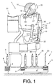
- Fig. 1 is a side view of a winding unit 2 one total of 4 bobbins marked with the reference number 1 manufacturing textile machine, in the embodiment of a Cross winder, shown during winding operation.
- Such automatic winding machines usually have a large number similar winding units 2. On these winding units 2 are on a ring spinning machine (not shown) produced spinning bobbins 9 to large-volume package, so-called cross-wound bobbins 11, rewound. The completed ones Cross-wound bobbins 11 are operated automatically Service unit on a package transport device 21 rolled out and then to a machine end side arranged (not shown) coil loading station or the like transported.
- Such automatic winder 1 usually also have a Logistics facility in the form of a coil and Sleeve transport system 3.
- a coil and Sleeve transport system 3 run, on transport plates 8, Spinning heads 9 or empty tubes 20 um.
- FIGS. 1 and 2 Of this extensive transport system 3 are shown in FIGS. 1 and 2 only the machine-long cop feed path 4, which is behind the winding units 2 running reversing section 5, one of the to the winding units 2 leading transverse transport routes 6 and the sleeve return path 7 shown.
- the delivered spinning heads 9 are in the Unwind positions 10, which are in the range of Cross transport routes 6 are, rewound to cross-wound bobbins 11.
- the individual winding units 2 have different, known facilities that have a proper Ensure the operation of these jobs.
- FIG. 1 at 30 is that of the spinning cop 9 to the cheese 11 running thread, with 12 a suction nozzle, with 22 a hook tube, at 13 a splicer, at 14 one Thread tensioning device, with 15 a thread cleaner with Thread cutting device as well as 16 one Paraffinizing device indicated.
- the Winding units 2 via a service unit, a so-called Cross-wound bobbin changer, supplied.
- This package changer ensures ensure that cross-wound bobbins 11 which have a predetermined diameter have reached, on the bobbin transport device 21st be carried out and that then from a Empty tube magazine each have an empty tube in the coil frame 18 is exchanged.
- FIG. 2 shows the situation on a winding unit 2 a winding interruption.
- Such an interruption in the winding it can happen, for example, if the thread cleaner 15 due to a detected thread fault the current Thread 30 has cut.
- the upper thread 34 runs open the surface 48 of the bobbin 11, while the bobbin thread 33 usually clamped in the thread tensioner 14 and for the subsequent thread connection process is kept ready.
- the suction nozzle 12 has already been pivoted into its upper position and tries to grasp the upper thread 34 lying on the surface 48 of the package 11.
- the cheese is rotated against its winding direction, as shown by arrow 24.
- the hook tube 22, which has gripped the lower thread 33 with the hook tube flap (not shown), is still in the waiting position shown.
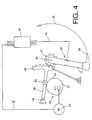
- both the gripper tube 22 and also the suction nozzle 12 via active connections, preferably Cam lever 29 or 31, with the cam disks 27 or 28 of a cam disk package 26 connected to a reversible electric drive 25 is connected.
- the Reversible drive 25 is via a control line 32 with the winding unit computer 39 of the winding unit 2 in question connected.
- a Sensor device 35 preferably an optical thread sensor is integrated, the presence of the thread start 48 of the Upper thread 34 is detected and the one via a signal line 45 is also connected to the winding unit computer 39.
- FIG. 4 schematically shows a preferred embodiment of the suction nozzle drive device.
- the reversible drive 25 connected to the winding station computer 39 via a control line 32 drives a cam disk package, of which only the cam disk 27 is shown.
- the roller 43 of a cam lever 29 pivotably mounted about the axis 42 rests on the guide contour 44 of this cam disk 27.
- the cam lever 29 has at the end a toothed segment 46 which meshes with a corresponding ring gear 47 on the suction nozzle 12, which is rotatably mounted about a pivot axis 40.
- an interruption of the winding occurs because for example, the thread is broken or because of the running thread 30 monitoring thread cleaner 15 a inadmissible thread defects and then his Thread trimmer has activated, usually the Lower thread 33 clamped in the thread tensioner 14 and there for the subsequent thread connection process ready.
- the upper thread 34 which in the case of a thread cut also the Has thread defects, however, runs on the surface 48 of the On the reel 11, which is lifted from the drive roller 17 and is braked to a standstill.
- the suction nozzle 12 For receiving the on the surface 48 of the package 11 accumulated upper thread 34, the suction nozzle 12 from the in 1 indicated starting position along the circular arc 36 pivoted into a position in which the suction nozzle 38 in Area of the surface 48 of the package 11 that slowly enters Unwinding direction 24 is rotated, is positioned.
- the Suction nozzle 12 normally remains for a short time (0.5 up to 1 sec.) in this position and then swivels, after the sensor device integrated in the suction nozzle 12 35 detects the sucked thread beginning 49 of the upper thread 34 has to return to its lower starting position.
- the upper thread 34 is inserted into the feed device 13.
- the lower thread 33 is pneumatic actable gripper tube 22 also in the Splice device 13 inserted.
- the gripper tube 22 pivots thereby along the circular arc 37 from its initial position in the thread insertion position shown in dashed lines in FIG. 2.
- the successful insertion of the lower thread 33 in the Splicing device 13 can by a (not shown) Bobbin thread sensor are monitored.
- Suction nozzle mouth 38 Due to the pitching movements of the suction nozzle 12 and thus the Suction nozzle mouth 38 become thread loops or the like possibly in the area of the suction nozzle mouth 38 caught (not shown) arranged needle comb, wound and the thread end 49 of the upper thread 34 correctly sucked into the suction nozzle 12.
Claims (4)
- Unité de bobinage d'une machine textile fabriquant des bobines à spires croisées, comprenant un épissoir pour relier un fil supérieur à un fil inférieur, sachant que le fil supérieur peut être manipulé à l'aide d'une buse d'aspiration présentant un capteur pour détecter le fil supérieur, laquelle peut pivoter à l'aide d'un moteur électrique entre une position dans laquelle l'ouverture de la buse d'aspiration est positionnée dans la zone de la surface d'une bobine réceptrice et une position dans laquelle le fil supérieur est introduit dans l'épissoir, caractérisée en ce que le moteur électrique (25) de la buse d'aspiration (12) peut être commandé de façon définie dans un sens de rotation comme dans l'autre par un calculateur de tête de bobinage (39), en ce que le capteur (35) de la buse d'aspiration (12) est également relié au calculateur de tête de bobinage (39) pour détecter un fil supérieur (34) correctement mis en place, et en ce que le calculateur (39) de la tête de bobinage est conçu de telle sorte que, lorsque le capteur (35) délivre un "signal négatif", il commute brièvement à plusieurs reprises le moteur (25) dans les deux sens de rotation et initie de ce fait un mouvement d'inclinaison de l'ouverture (38) de la buse d'aspiration dans la zone de la surface (48) de la bobine réceptrice (11).
- Unité de bobinage selon la revendication 1, caractérisée en ce que le capteur intégré dans la buse d'aspiration (12) est réalisé en tant que capteur otique de fil (35).
- Unité de bobinage selon les revendications 1 et 2, caractérisée en ce que la buse d'aspiration (12) est reliée au moteur réversible (25) par l'intermédiaire d'un levier coudé (29) et d'une came (27), la came (27) présentant un contour (44) tel qu'il permet une rotation de la came (27) tant dans le sens des aiguilles d'une montre que dans le sens inverse des aiguilles d'une montre.
- Unité de bobinage selon l'une des revendications précédentes, caractérisée en ce que le temps passé par l'ouverture (38) de la buse d'aspiration dans la zone de la surface (48) de la bobine réceptrice (11) est réglable de façon définie par le biais de temps d'arrêt du moteur (25) définissables au préalable.
Applications Claiming Priority (2)
| Application Number | Priority Date | Filing Date | Title |
|---|---|---|---|
| DE19650933 | 1996-12-07 | ||
| DE19650933A DE19650933A1 (de) | 1996-12-07 | 1996-12-07 | Spulaggregat einer Kreuzspulen herstellenden Textilmaschine |
Publications (2)
| Publication Number | Publication Date |
|---|---|
| EP0846641A1 EP0846641A1 (fr) | 1998-06-10 |
| EP0846641B1 true EP0846641B1 (fr) | 2002-06-12 |
Family
ID=7814003
Family Applications (1)
| Application Number | Title | Priority Date | Filing Date |
|---|---|---|---|
| EP97119580A Expired - Lifetime EP0846641B1 (fr) | 1996-12-07 | 1997-11-08 | Unité de bobinage d'une machine textile pour la fabrication de bobines à spires croisées |
Country Status (5)
| Country | Link |
|---|---|
| US (1) | US5950957A (fr) |
| EP (1) | EP0846641B1 (fr) |
| JP (1) | JPH10167577A (fr) |
| DE (2) | DE19650933A1 (fr) |
| TR (1) | TR199701455A2 (fr) |
Cited By (1)
| Publication number | Priority date | Publication date | Assignee | Title |
|---|---|---|---|---|
| DE102015102457A1 (de) | 2015-02-20 | 2016-08-25 | Rieter Ingolstadt Gmbh | Verfahren zur Steuerung eines Ansetzprozesses |
Families Citing this family (16)
| Publication number | Priority date | Publication date | Assignee | Title |
|---|---|---|---|---|
| DE19938432A1 (de) * | 1999-08-13 | 2001-02-15 | Schlafhorst & Co W | Fadenverbindungseinrichtung für eine Kreuzspulen herstellende Textilmaschine |
| DE10020665A1 (de) * | 2000-04-27 | 2001-10-31 | Schlafhorst & Co W | Verfahren zum Betreiben einer Kreuzspulen herstellenden Textilmaschine |
| DE102004051038A1 (de) * | 2004-10-20 | 2006-04-27 | Saurer Gmbh & Co. Kg | Fadenspleißvorrichtung |
| DE102006006390A1 (de) * | 2006-02-11 | 2007-08-16 | Saurer Gmbh & Co. Kg | Fadenspleißvorrichtung für eine Kreuzspulen herstellende Textilmaschine |
| DE102006026548A1 (de) * | 2006-06-08 | 2007-12-13 | Oerlikon Textile Gmbh & Co. Kg | Verfahren zum Betreiben einer Arbeitstelle einer Kreutzspulen herstellenden Textilmaschine |
| DE102006039735A1 (de) * | 2006-08-24 | 2008-02-28 | Oerlikon Textile Gmbh & Co. Kg | Saugdüse für eine Arbeitsstelle einer Kreuzspulen herstellenden Textilmaschine |
| DE102008057321A1 (de) * | 2008-11-14 | 2010-05-20 | Oerlikon Textile Gmbh & Co. Kg | Arbeitsstelle einer Spulmaschine mit einem saugluftbeaufschlagten Greiferrohr |
| JP2011144029A (ja) * | 2010-01-17 | 2011-07-28 | Murata Machinery Ltd | 糸巻取り装置 |
| JP5471923B2 (ja) * | 2010-07-15 | 2014-04-16 | 村田機械株式会社 | 糸巻取装置 |
| DE102012016854A1 (de) * | 2012-08-25 | 2014-02-27 | Saurer Germany Gmbh & Co. Kg | Verfahren zum Verbinden eines Ober- und Unterfadens an einer Arbeitsstelle einer Spulmaschine und Arbeitsstelle einer Spulmaschine |
| DE102013004053A1 (de) * | 2013-03-08 | 2014-09-11 | Saurer Germany Gmbh & Co. Kg | Verfahren zum Betreiben einer Arbeitsstelle einer Kreuzspulen herstellenden Textilmaschine bzw. zugehörige Arbeitsstelle |
| JP2015148035A (ja) * | 2014-02-10 | 2015-08-20 | 村田機械株式会社 | 糸捕捉装置、及び、糸巻取機 |
| DE102016108423A1 (de) * | 2016-05-06 | 2017-11-09 | Rieter Ingolstadt Gmbh | Verfahren zum Handhaben eines Fadenendes und Spulstelle |
| DE102016115731A1 (de) * | 2016-08-24 | 2018-03-01 | Saurer Germany Gmbh & Co. Kg | Saugvorrichtung zum Einsaugen eines Fadenendes eines auf einer Auflaufspule aufgespulten Fadens und Verfahren zum sensorischen Überwachen eines Saugkanalabschnitts der Saugvorrichtung |
| JP2019043737A (ja) * | 2017-09-04 | 2019-03-22 | 村田機械株式会社 | 糸巻取機 |
| CN111517167A (zh) * | 2020-03-26 | 2020-08-11 | 青岛宏大纺织机械有限责任公司 | 一种实现筒纱吸嘴点动吸纱的方法 |
Family Cites Families (10)
| Publication number | Priority date | Publication date | Assignee | Title |
|---|---|---|---|---|
| DE2123641A1 (en) * | 1971-05-12 | 1972-11-16 | Skf Kugellagerfabriken Gmbh, 8720 Schweinfurt | Photo-electric thread sensors - senses modulation of signal by passing thread |
| US3918651A (en) * | 1973-07-02 | 1975-11-11 | Murata Machinery Ltd | Method and device for readying of yarn ends, particularly in yarn-winding machines |
| JPH02100971A (ja) * | 1988-10-07 | 1990-04-12 | Murata Mach Ltd | 自動ワインダーにおける糸継制御装置 |
| EP0427990B1 (fr) * | 1989-11-14 | 1994-12-21 | W. SCHLAFHORST AG & CO. | Dispositif pour exécuter automatiquement le raccordement de fil ainsi que le changement de cannettes, constitués par une suite fixe d'opérations à un poste de bobinage d'une machine de bobinage |
| DE4004028C2 (de) * | 1990-02-10 | 2001-06-07 | Schlafhorst & Co W | Verfahren und Vorrichtung zum Bilden einer Fadenreserve auf einer Kreuzspule |
| JPH05246626A (ja) * | 1992-03-05 | 1993-09-24 | Murata Mach Ltd | 巻取ユニットの糸継制御方法 |
| EP0562169A1 (fr) * | 1992-03-26 | 1993-09-29 | Murao And Company Limited | Dispositif pour saisir le bout du fils d'un tube passe-fil |
| DE4222377C2 (de) * | 1992-07-08 | 2002-06-27 | Schlafhorst & Co W | Verfahren und Vorrichtung zum Erfassen eines auf einer Kreuzspule angeordneten Fadenendes |
| DE4231958A1 (de) * | 1992-09-24 | 1994-03-31 | Schlafhorst & Co W | Verfahren und Vorrichtung zum Einlegen von Fadenenden in eine Fadenendenverbindungsvorrichtung |
| DE4434610B4 (de) * | 1994-09-28 | 2005-07-21 | Saurer Gmbh & Co. Kg | Verfahren und Vorrichtung zum Wickeln eines Fadens |
-
1996
- 1996-12-07 DE DE19650933A patent/DE19650933A1/de not_active Withdrawn
-
1997
- 1997-11-08 DE DE59707488T patent/DE59707488D1/de not_active Expired - Lifetime
- 1997-11-08 EP EP97119580A patent/EP0846641B1/fr not_active Expired - Lifetime
- 1997-11-28 TR TR97/01455A patent/TR199701455A2/xx unknown
- 1997-12-04 JP JP9334207A patent/JPH10167577A/ja active Pending
- 1997-12-04 US US08/985,421 patent/US5950957A/en not_active Expired - Fee Related
Cited By (1)
| Publication number | Priority date | Publication date | Assignee | Title |
|---|---|---|---|---|
| DE102015102457A1 (de) | 2015-02-20 | 2016-08-25 | Rieter Ingolstadt Gmbh | Verfahren zur Steuerung eines Ansetzprozesses |
Also Published As
| Publication number | Publication date |
|---|---|
| JPH10167577A (ja) | 1998-06-23 |
| EP0846641A1 (fr) | 1998-06-10 |
| US5950957A (en) | 1999-09-14 |
| DE19650933A1 (de) | 1998-06-10 |
| DE59707488D1 (de) | 2002-07-18 |
| TR199701455A2 (xx) | 1998-06-22 |
Similar Documents
| Publication | Publication Date | Title |
|---|---|---|
| EP0846641B1 (fr) | Unité de bobinage d'une machine textile pour la fabrication de bobines à spires croisées | |
| EP2029465B1 (fr) | Procédé de fonctionnement du poste de travail d'une machine textile produisant des bobines croisées | |
| EP1428783B1 (fr) | Méthode et dispositif de mise en service d'un poste de travail d'une machine textile pour la fabrication de bobines à spires croisées | |
| EP0995711B1 (fr) | Procédé pour actionner un poste de travail d' un bobinoir | |
| DE19640184A1 (de) | Verfahren zum Ausreinigen von Garnfehlern an einer Spulstelle einer Spulmaschine | |
| EP2338818B1 (fr) | Procédé de fonctionnement d'un poste de travail d'une bobineuse et poste de travail d'une bobineuse | |
| EP1928773B1 (fr) | Procede d'insertion d'un fil | |
| DE4434610B4 (de) | Verfahren und Vorrichtung zum Wickeln eines Fadens | |
| EP0325992A1 (fr) | Procédé et dispositif pour remettre en marche l'opération de filature après une interruption | |
| DE102009009971A1 (de) | Verfahren und Vorrichtung zum Betreiben einer Arbeitsstelle einer Kreuzspulen herstellenden Textilmaschine sowie Arbeitsstelle zur Durchführung des Verfahrens | |
| DE4139892C2 (de) | Verfahren zur Herstellung einer Fadenverbindung an einer Spulstelle einer Spulmaschine | |
| EP1028080B1 (fr) | Procédé de fonctionnement d'un poste de travail d'une machine textile pour la fabrication de bobines à spires croisées | |
| DE102006006390A1 (de) | Fadenspleißvorrichtung für eine Kreuzspulen herstellende Textilmaschine | |
| EP2388224A2 (fr) | Agrégat de commande | |
| EP2279976B1 (fr) | Procédé destiné au fonctionnement de postes de travail d'une machine textile produisant des bobines croisées | |
| EP1076028B1 (fr) | Dispositif de rattachement du fil pour une machine textile fabriquant des bobines à spires croisées | |
| DE3819873C2 (fr) | ||
| EP1127831B1 (fr) | Dispositif de mise en service d'un poste de travail d'une machine textile pour la fabrication de bobines à spires croisées | |
| DE102012005988A1 (de) | Verfahren zum Betreiben einer Arbeitsstelle einer Kreuzspulen herstellenden Textilmaschine | |
| DE102017117743A1 (de) | Vorrichtung zur Ausreinigung von Garnfehlern aus einem Garn | |
| DE10020665A1 (de) | Verfahren zum Betreiben einer Kreuzspulen herstellenden Textilmaschine | |
| DE102008050070A1 (de) | Vorrichtung zur automatischen Inbetriebnahme einer Arbeitsstelle einer Kreuzspulen herstellenden Textilmaschine | |
| DE4017303C2 (de) | Verfahren zur Herstellung von Kreuzspulen mit unterschiedlicher Garnlänge | |
| DE102009033377A1 (de) | Verfahren und Vorrichtung zum Betreiben einer Arbeitsstelle einer Kreuzspulen herstellenden Textilmaschine | |
| DE202007011864U1 (de) | Vorrichtung zum Betreiben der Arbeitsstellen von Kreuzspulen herstellenden Textilmaschinen |
Legal Events
| Date | Code | Title | Description |
|---|---|---|---|
| PUAI | Public reference made under article 153(3) epc to a published international application that has entered the european phase |
Free format text: ORIGINAL CODE: 0009012 |
|
| AK | Designated contracting states |
Kind code of ref document: A1 Designated state(s): BE CH DE ES FR GB IT LI |
|
| 17P | Request for examination filed |
Effective date: 19981210 |
|
| AKX | Designation fees paid |
Free format text: BE CH DE ES FR GB IT LI |
|
| RBV | Designated contracting states (corrected) |
Designated state(s): BE CH DE ES FR GB IT LI |
|
| 17Q | First examination report despatched |
Effective date: 20010129 |
|
| GRAG | Despatch of communication of intention to grant |
Free format text: ORIGINAL CODE: EPIDOS AGRA |
|
| GRAG | Despatch of communication of intention to grant |
Free format text: ORIGINAL CODE: EPIDOS AGRA |
|
| GRAH | Despatch of communication of intention to grant a patent |
Free format text: ORIGINAL CODE: EPIDOS IGRA |
|
| GRAH | Despatch of communication of intention to grant a patent |
Free format text: ORIGINAL CODE: EPIDOS IGRA |
|
| GRAA | (expected) grant |
Free format text: ORIGINAL CODE: 0009210 |
|
| AK | Designated contracting states |
Kind code of ref document: B1 Designated state(s): BE CH DE ES FR GB IT LI |
|
| PG25 | Lapsed in a contracting state [announced via postgrant information from national office to epo] |
Ref country code: GB Free format text: LAPSE BECAUSE OF FAILURE TO SUBMIT A TRANSLATION OF THE DESCRIPTION OR TO PAY THE FEE WITHIN THE PRESCRIBED TIME-LIMIT Effective date: 20020612 Ref country code: FR Free format text: LAPSE BECAUSE OF FAILURE TO SUBMIT A TRANSLATION OF THE DESCRIPTION OR TO PAY THE FEE WITHIN THE PRESCRIBED TIME-LIMIT Effective date: 20020612 |
|
| REG | Reference to a national code |
Ref country code: GB Ref legal event code: FG4D Free format text: NOT ENGLISH |
|
| REG | Reference to a national code |
Ref country code: CH Ref legal event code: EP |
|
| REF | Corresponds to: |
Ref document number: 59707488 Country of ref document: DE Date of ref document: 20020718 |
|
| PGFP | Annual fee paid to national office [announced via postgrant information from national office to epo] |
Ref country code: GB Payment date: 20021021 Year of fee payment: 6 |
|
| PGFP | Annual fee paid to national office [announced via postgrant information from national office to epo] |
Ref country code: BE Payment date: 20021121 Year of fee payment: 6 |
|
| GBV | Gb: ep patent (uk) treated as always having been void in accordance with gb section 77(7)/1977 [no translation filed] |
Effective date: 20020612 |
|
| PG25 | Lapsed in a contracting state [announced via postgrant information from national office to epo] |
Ref country code: ES Free format text: LAPSE BECAUSE OF FAILURE TO SUBMIT A TRANSLATION OF THE DESCRIPTION OR TO PAY THE FEE WITHIN THE PRESCRIBED TIME-LIMIT Effective date: 20021220 |
|
| EN | Fr: translation not filed | ||
| PLBE | No opposition filed within time limit |
Free format text: ORIGINAL CODE: 0009261 |
|
| STAA | Information on the status of an ep patent application or granted ep patent |
Free format text: STATUS: NO OPPOSITION FILED WITHIN TIME LIMIT |
|
| 26N | No opposition filed |
Effective date: 20030313 |
|
| PG25 | Lapsed in a contracting state [announced via postgrant information from national office to epo] |
Ref country code: BE Free format text: LAPSE BECAUSE OF NON-PAYMENT OF DUE FEES Effective date: 20031130 |
|
| BERE | Be: lapsed |
Owner name: W. *SCHLAFHORST & CO. Effective date: 20031130 |
|
| PGFP | Annual fee paid to national office [announced via postgrant information from national office to epo] |
Ref country code: CH Payment date: 20051122 Year of fee payment: 9 |
|
| PG25 | Lapsed in a contracting state [announced via postgrant information from national office to epo] |
Ref country code: LI Free format text: LAPSE BECAUSE OF NON-PAYMENT OF DUE FEES Effective date: 20061130 Ref country code: CH Free format text: LAPSE BECAUSE OF NON-PAYMENT OF DUE FEES Effective date: 20061130 |
|
| REG | Reference to a national code |
Ref country code: CH Ref legal event code: PL |
|
| REG | Reference to a national code |
Ref country code: DE Ref legal event code: R081 Ref document number: 59707488 Country of ref document: DE Owner name: SAURER GERMANY GMBH & CO. KG, DE Free format text: FORMER OWNER: OERLIKON TEXTILE GMBH & CO. KG, 42897 REMSCHEID, DE Effective date: 20130918 |
|
| PGFP | Annual fee paid to national office [announced via postgrant information from national office to epo] |
Ref country code: DE Payment date: 20141126 Year of fee payment: 18 |
|
| PGFP | Annual fee paid to national office [announced via postgrant information from national office to epo] |
Ref country code: IT Payment date: 20141121 Year of fee payment: 18 |
|
| REG | Reference to a national code |
Ref country code: DE Ref legal event code: R119 Ref document number: 59707488 Country of ref document: DE |
|
| PG25 | Lapsed in a contracting state [announced via postgrant information from national office to epo] |
Ref country code: IT Free format text: LAPSE BECAUSE OF NON-PAYMENT OF DUE FEES Effective date: 20151108 |
|
| PG25 | Lapsed in a contracting state [announced via postgrant information from national office to epo] |
Ref country code: DE Free format text: LAPSE BECAUSE OF NON-PAYMENT OF DUE FEES Effective date: 20160601 |