EP0845374B1 - Procédé de marquage de pneus - Google Patents
Procédé de marquage de pneus Download PDFInfo
- Publication number
- EP0845374B1 EP0845374B1 EP97120888A EP97120888A EP0845374B1 EP 0845374 B1 EP0845374 B1 EP 0845374B1 EP 97120888 A EP97120888 A EP 97120888A EP 97120888 A EP97120888 A EP 97120888A EP 0845374 B1 EP0845374 B1 EP 0845374B1
- Authority
- EP
- European Patent Office
- Prior art keywords
- tire
- axis
- marking
- marking head
- mark
- Prior art date
- Legal status (The legal status is an assumption and is not a legal conclusion. Google has not performed a legal analysis and makes no representation as to the accuracy of the status listed.)
- Expired - Lifetime
Links
Images


Classifications
-
- G—PHYSICS
- G01—MEASURING; TESTING
- G01M—TESTING STATIC OR DYNAMIC BALANCE OF MACHINES OR STRUCTURES; TESTING OF STRUCTURES OR APPARATUS, NOT OTHERWISE PROVIDED FOR
- G01M1/00—Testing static or dynamic balance of machines or structures
- G01M1/14—Determining unbalance
- G01M1/16—Determining unbalance by oscillating or rotating the body to be tested
- G01M1/26—Determining unbalance by oscillating or rotating the body to be tested with special adaptations for marking, e.g. by drilling
-
- B—PERFORMING OPERATIONS; TRANSPORTING
- B29—WORKING OF PLASTICS; WORKING OF SUBSTANCES IN A PLASTIC STATE IN GENERAL
- B29D—PRODUCING PARTICULAR ARTICLES FROM PLASTICS OR FROM SUBSTANCES IN A PLASTIC STATE
- B29D30/00—Producing pneumatic or solid tyres or parts thereof
- B29D30/06—Pneumatic tyres or parts thereof (e.g. produced by casting, moulding, compression moulding, injection moulding, centrifugal casting)
- B29D30/0601—Vulcanising tyres; Vulcanising presses for tyres
- B29D30/0633—After-treatment specially adapted for vulcanising tyres
-
- B—PERFORMING OPERATIONS; TRANSPORTING
- B60—VEHICLES IN GENERAL
- B60C—VEHICLE TYRES; TYRE INFLATION; TYRE CHANGING; CONNECTING VALVES TO INFLATABLE ELASTIC BODIES IN GENERAL; DEVICES OR ARRANGEMENTS RELATED TO TYRES
- B60C13/00—Tyre sidewalls; Protecting, decorating, marking, or the like, thereof
- B60C13/001—Decorating, marking or the like
-
- B—PERFORMING OPERATIONS; TRANSPORTING
- B29—WORKING OF PLASTICS; WORKING OF SUBSTANCES IN A PLASTIC STATE IN GENERAL
- B29D—PRODUCING PARTICULAR ARTICLES FROM PLASTICS OR FROM SUBSTANCES IN A PLASTIC STATE
- B29D30/00—Producing pneumatic or solid tyres or parts thereof
- B29D30/06—Pneumatic tyres or parts thereof (e.g. produced by casting, moulding, compression moulding, injection moulding, centrifugal casting)
- B29D30/72—Side-walls
- B29D2030/728—Decorating or marking the sidewalls after tyre vulcanization
Definitions
- the present invention relates to a method of marking a tire to indicate the taper vector direction and the plane of the radial force first harmonic (RF1H) vector.
- Indications of this sort are important both when assembling the tire to the wheel rim - to improve wheel balance, the tire is advantageously connected vectorially to the rim so that the respective first harmonic points are opposite - and when assembling the wheels to the vehicle - each pair of opposite wheels must be assembled with opposite tapers.
- number 1 indicates a unit for testing and marking tires 2, and comprising a known test machine (TUO) 3, and a machine 4 for marking tires 2.
- Machine 3 provides for making a series of measurements of tires 2, and determining, among other things, the taper vector direction and the location of the plane 5 ( Figures 2 and 4b) of the radial force first harmonic (RF1H) vector; and machine 4 cooperates with test machine 3 to make a single mark 6 ( Figures 2 and 4b) on tire 2, in plane 5 and preferably on the positive taper side, i.e. on the taper vector out side.
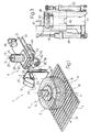
- machine 4 comprises a marking head 17; and an actuating device 18 for moving head 17 in space with respect to an adjustable assembly 19 supporting device 18.
- Supporting assembly 19 comprises a tubular body 20 with a vertical axis 21 and closed at the top by a wall 22 connected integrally to a fixed frame 23.
- a piston 24 is housed in sliding and angularly-fixed manner inside body 20, and is connected to wall 22 by a screw 25 extending along axis 21 and engaging a nut screw 26 formed through an end wall 27 of piston 24.
- Screw 25 extends in rotary and axially-fixed manner through wall 22, and comprises, over body 20, an end coupling 28 connected to the output of a motor 29 or, according to a variation not shown, engaged by a hand tool (not shown) to adjust the axial position of piston 24 with respect to body 20.
- piston 24 comprises an annular flange 30 connected integrally to a horizontal guide 31 located over conveyor 7 and parallel to the traveling direction 32 of tires 2 along conveyor 7.
- the bottom surface of guide 31 is fitted with a slide 33, which is moved along guide 31 in a direction 34 parallel to direction 32 by an actuating device 35 comprising a screw 36, which is connected in rotary and axially-fixed manner to a support 37 integral with guide 31, and engages a nut screw 38 fitted to slide 33.
- Actuating device 35 also comprises a motor 39 fitted to guide 31, and the output of which is connected to one end of screw 36 to rotate it about an axis 40 parallel to direction 34.
- motor 39 is eliminated, and the free end of screw 36 comprises a shank (not shown) engaged by a tool or handwheel to operate screw 36 manually.
- device 18 also comprises a plate 41 located over conveyor 7 and perpendicular to conveyor 7 and directions 32 and 34.
- Plate 41 is connected integrally to one end of a shaft 42 fitted in rotary manner to slide 33 by means of two supports 43 and forming the output shaft of a motor 44, which is fitted to slide 33 and located, together with shaft 42 and supports 43, beneath slide 33 and between slide 33 and conveyor 7 to rotate shaft 42 about and axis 45 parallel to directions 32 and 34.
- Head 17 comprises a marking member 54, which, when brought substantially into contact with shoulder 2a, 2b of a tire 2, provides for making mark 6 on shoulder 2a, 2b.
- tires 2 are fed by conveyor 7 in direction 32 and arrested, centered over opening 16, at station 8.
- the tire 2 over opening 16 is then lifted vertically by spindle 10 and connected to spindle 9, which is activated to rotate both tire 2 and spindle 10 about axis 11 to enable machine 3 to perform the measurements provided for.
- machine 4 is maintained in an initial idle position in which axes 40 and 45 are parallel to direction 32, and head 17 is located at a higher level than upper shoulder 2a, is located upstream from tire 2 in direction 32, and is separated from axis 11 by a distance greater than the radius of tire 2.
- Said idle position is set by means of an initial setting of machine 4, wherein the position of piston 24 with respect to tubular body 20 is adjusted by means of screw 25 so that axis 45 is substantially located in the equatorial plane 55 of tire 2.
Claims (13)
- Procédé de marquage d'un pneu (2) pour indiquer la direction du vecteur de conicité et le plan (5) du point haut de première harmonique (P) ; le pneu (2) comprenant un premier et un deuxième épaulement (2a, 2b) ; et le procédé étant caractérisé en ce qu'il comprend une phase de marquage dans laquelle une marque unique (6) est réalisée sur le pneu (2), dans ledit plan (5) et sur l'un ou l'autre desdits épaulements (2a, 2b) selon la direction du vecteur de conicité.
- Procédé selon la revendication 1, caractérisé en ce qu'il comprend également les phases consistant à distribuer le pneu (2), au moyen d'un transporteur (7), dans une direction donnée (32) jusqu'à une station d'essais et de marquage (8) ; faire tourner le pneu (2) autour d'un premier axe (11) pour déterminer la direction du vecteur de conicité et le plan (5) du point haut de première harmonique (P) du pneu (2) ; et arrêter le pneu (2) avant application de ladite marque (6).
- Procédé selon la revendication 2, caractérisé en ce que ledit premier axe (11) est un axe sensiblement vertical ; le pneu (2) étant soulevé du transporteur (7) dans une direction parallèle audit premier axe (11) avant d'être tourné.
- Procédé selon l'une quelconque des revendications précédentes, caractérisé en ce que ladite marque (6) est appliquée par une tête de marquage (17) montée sur un dispositif à axes multiples (18) pour déplacer la tête de marquage (17) afin de coopérer sélectivement avec chacun desdits épaulements (2a, 2b).
- Procédé selon la revendication 4, caractérisé en ce que le pneu (2) comprend un premier axe (11) de rotation ; ladite tête de marquage (17) étant déplacée, au cours de ladite phase de marquage, d'une position de repos initiale dans laquelle ladite tête de marquage (17) est séparée dudit premier axe (11) d'une distance supérieure à un rayon dudit pneu (2).
- Procédé selon la revendication 5, caractérisé en ce que ledit premier axe (11) est un axe sensiblement vertical ; ladite tête de marquage (17) étant située, dans ladite position de repos initiale, à un niveau plus élevé que le plus haut desdits deux épaulements (2a, 2b).
- Procédé selon l'une quelconque des revendications précédentes 4 à 6, caractérisé en ce que, avant application de ladite marque (6), le pneu est arrêté avec ledit plan (5) dans une position dans laquelle le plan (5) fait face à ladite tête de marquage (17).
- Procédé selon la revendication 6 ou 7, caractérisé en ce que ladite phase de marquage comprend la phase annexe de translation de ladite tête de marquage (17), transversalement par rapport audit premier axe (11), jusque et depuis une position intermédiaire en face d'un desdits épaulements (2a, 2b).
- Procédé selon la revendication 8, caractérisé en ce que ladite tête de marquage (17) est déplacée par translation dans ladite position intermédiaire depuis ladite position de repos initiale.
- Procédé selon la revendication 8, caractérisé en ce que, avant d'être déplacée par translation dans ladite position intermédiaire, ladite tête de marquage (17) est tournée autour d'un deuxième axe (45), transversalement au premier axe (11), de ladite position de repos initiale à une position abaissée dans laquelle la tête de marquage (17) est située à un niveau plus bas que le plus bas desdits deux épaulements (2a, 2b).
- Procédé selon la revendication 10, caractérisé en ce que ladite tête de marquage (17) est déplacée par translation dans ladite position intermédiaire depuis ladite position abaissée.
- Procédé selon l'une quelconque des revendications précédentes 8 à 11, caractérisé en ce que ladite phase de marquage comprend également la phase annexe de déplacement de ladite tête de marquage (17), dans une direction (47) parallèle au premier axe (11), entre ladite position intermédiaire et une position opérante contactant sensiblement undit épaulement (2a, 2b).
- Procédé selon la revendication 12, caractérisé en ce que ladite marque (6) est appliquée en déplaçant ladite tête de marquage (17), de ladite position opérante, autour d'un troisième axe (53) transversalement audit premier axe (11).
Applications Claiming Priority (2)
| Application Number | Priority Date | Filing Date | Title |
|---|---|---|---|
| ITTO960972 | 1996-11-29 | ||
| IT96TO000972A IT1289701B1 (it) | 1996-11-29 | 1996-11-29 | Metodo per la marcatura di un pneumatico |
Publications (3)
| Publication Number | Publication Date |
|---|---|
| EP0845374A2 EP0845374A2 (fr) | 1998-06-03 |
| EP0845374A3 EP0845374A3 (fr) | 1998-12-30 |
| EP0845374B1 true EP0845374B1 (fr) | 2002-02-06 |
Family
ID=11415066
Family Applications (1)
| Application Number | Title | Priority Date | Filing Date |
|---|---|---|---|
| EP97120888A Expired - Lifetime EP0845374B1 (fr) | 1996-11-29 | 1997-11-27 | Procédé de marquage de pneus |
Country Status (6)
| Country | Link |
|---|---|
| US (1) | US5905199A (fr) |
| EP (1) | EP0845374B1 (fr) |
| JP (1) | JP4028052B2 (fr) |
| DE (1) | DE69710299T2 (fr) |
| ES (1) | ES2170913T3 (fr) |
| IT (1) | IT1289701B1 (fr) |
Families Citing this family (16)
| Publication number | Priority date | Publication date | Assignee | Title |
|---|---|---|---|---|
| JPH11278020A (ja) * | 1998-03-26 | 1999-10-12 | Bridgestone Corp | マーキング検査装置 |
| JP2000280264A (ja) | 1999-01-27 | 2000-10-10 | Bridgestone Corp | タイヤのユニフォーミティ修正方法及びそれを適用したタイヤ |
| US6676789B1 (en) | 1999-05-20 | 2004-01-13 | The Goodyear Tire And Rubber Company | Tire building apparatus |
| AU4100899A (en) * | 1999-05-27 | 2000-12-18 | Goodyear Tire And Rubber Company, The | Protective paint applications to tires |
| JP4885370B2 (ja) * | 2000-06-16 | 2012-02-29 | 株式会社ブリヂストン | 印刷装置、及び印刷方法 |
| ITTO20010389A1 (it) * | 2001-04-20 | 2002-10-20 | Bridgestone Firestone Tech | Impianto e metodo per la produzione di pmeumatici con controllo in linea della conducibilita' elettrica. |
| JP4928105B2 (ja) * | 2005-09-21 | 2012-05-09 | 住友ゴム工業株式会社 | 空気入りタイヤの製造方法及びそれに用いるカラーラインの塗装装置 |
| JP5749946B2 (ja) * | 2011-03-10 | 2015-07-15 | 株式会社ブリヂストン | タイヤ用印刷装置およびタイヤ表面印刷方法 |
| JP6034759B2 (ja) * | 2013-06-27 | 2016-11-30 | 株式会社神戸製鋼所 | マーキング装置 |
| CN104260562B (zh) * | 2014-10-01 | 2016-03-23 | 合肥海闻自动化设备有限公司 | 一种用于轮胎数字打印机的轮胎夹具 |
| US20160355060A1 (en) * | 2015-02-05 | 2016-12-08 | Mitsubishi Heavy Industries Machinery Technology Corporation | Tire marking apparatus |
| DE102015217632A1 (de) * | 2015-09-15 | 2017-03-16 | Zf Friedrichshafen Ag | Verfahren zum Markieren eines Reifens und Vorrichtung zur Durchführung |
| CN105346218A (zh) * | 2015-11-11 | 2016-02-24 | 万达工业(始兴)有限公司 | 一种自动移印机 |
| CN105236071A (zh) * | 2015-11-11 | 2016-01-13 | 万达工业(始兴)有限公司 | 一种轮胎自动移印机 |
| EP3238928B1 (fr) * | 2016-04-28 | 2020-07-01 | 4JET Technologies GmbH | Synchronisation d'informations sur un pneu |
| JP2019174449A (ja) * | 2018-03-29 | 2019-10-10 | 株式会社神戸製鋼所 | タイヤ試験機及びタイヤのマーキング方法 |
Family Cites Families (10)
| Publication number | Priority date | Publication date | Assignee | Title |
|---|---|---|---|---|
| US1489922A (en) * | 1922-10-04 | 1924-04-08 | Miller Rubber Co | Air-bag-buffing machine |
| US1850238A (en) * | 1929-05-31 | 1932-03-22 | Fisk Rubber Co | Apparatus for spraying annular articles |
| FR1233945A (fr) * | 1959-08-27 | 1960-10-13 | Hofmann K G Fa Geb | Dispositif pour caractériser des pneumatiques de véhicules automobiles |
| US3526131A (en) * | 1968-09-09 | 1970-09-01 | Goodyear Tire & Rubber | Tire marking apparatus |
| US4260889A (en) * | 1979-11-28 | 1981-04-07 | The Firestone Tire & Rubber Company | Defect marker method and apparatus for use with tire inspection machines |
| US4308747A (en) * | 1980-03-27 | 1982-01-05 | The B. F. Goodrich Company | Apparatus for marking radial first harmonic high point on a tire |
| JPS5993343A (ja) * | 1982-11-19 | 1984-05-29 | Yokohama Rubber Co Ltd:The | タイヤのマ−キング装置 |
| US4670289A (en) * | 1985-02-28 | 1987-06-02 | The Firestone Tire & Rubber Company | Tire marker |
| US5237505A (en) * | 1991-05-03 | 1993-08-17 | Illinois Toll Works Inc. | Method and apparatus utilizing static imbalance to reduce vibration caused by tire/wheel assemblies and tire/wheel assembly made using same |
| JP2515179B2 (ja) * | 1991-03-19 | 1996-07-10 | 住友ゴム工業株式会社 | マ―キング装置 |
-
1996
- 1996-11-29 IT IT96TO000972A patent/IT1289701B1/it active IP Right Grant
-
1997
- 1997-11-20 US US08/975,178 patent/US5905199A/en not_active Expired - Lifetime
- 1997-11-26 JP JP32504597A patent/JP4028052B2/ja not_active Expired - Lifetime
- 1997-11-27 DE DE69710299T patent/DE69710299T2/de not_active Expired - Lifetime
- 1997-11-27 EP EP97120888A patent/EP0845374B1/fr not_active Expired - Lifetime
- 1997-11-27 ES ES97120888T patent/ES2170913T3/es not_active Expired - Lifetime
Also Published As
| Publication number | Publication date |
|---|---|
| JPH10236116A (ja) | 1998-09-08 |
| DE69710299T2 (de) | 2002-06-27 |
| ES2170913T3 (es) | 2002-08-16 |
| US5905199A (en) | 1999-05-18 |
| JP4028052B2 (ja) | 2007-12-26 |
| ITTO960972A1 (it) | 1998-05-29 |
| EP0845374A3 (fr) | 1998-12-30 |
| EP0845374A2 (fr) | 1998-06-03 |
| IT1289701B1 (it) | 1998-10-16 |
| DE69710299D1 (de) | 2002-03-21 |
Similar Documents
| Publication | Publication Date | Title |
|---|---|---|
| EP0845374B1 (fr) | Procédé de marquage de pneus | |
| EP0400003B1 (fr) | Machine de controle de pneus ayant une largeur de bourrelet adaptable | |
| AU766962B2 (en) | Snug fitting apparatus for tire assembly | |
| US7240543B2 (en) | Tire positioning sensor | |
| JP2713708B2 (ja) | タイヤのサイドウオールを研削する装置及び方法 | |
| EP1464942B1 (fr) | Appareil et procédé de mesure du balourd d'un pneu sur une machine de test de variations de force | |
| US9429498B2 (en) | Tire testing machine | |
| US3698233A (en) | Apparatus for processing cured tires | |
| CA2060109C (fr) | Methode et appareil permettant de polir les flancs de pneus | |
| US6086452A (en) | Method of high speed centrifugal run-out grinding of a pneumatic tire | |
| EP0130759B1 (fr) | Appareil de meulage uniforme de pneumatiques | |
| US5719331A (en) | Bead width adjusting apparatus for tire uniformity machines | |
| US4885875A (en) | Lens edging machine and method | |
| US3656343A (en) | Apparatus for processing cured tires | |
| EP0275088B1 (fr) | Machine et méthode d'essai d'uniformité de pneus | |
| EP0522667A1 (fr) | Support pour pneus | |
| JPH07243947A (ja) | タイヤユニフォミティ機のランナウト装置 | |
| US5255728A (en) | Automatic spew trimming method and apparatus used therefor | |
| JPS63281832A (ja) | 更正タイヤの製造方法およびその装置 | |
| US4768764A (en) | Green tire holder | |
| US20050000662A1 (en) | Device for optimizing bead seating | |
| CN208860612U (zh) | 零点精准刹擎定位装置 | |
| JP3953200B2 (ja) | グラインダのスキム調整装置 | |
| JPH04201170A (ja) | 長尺軸の外面研削装置 | |
| CN113405430A (zh) | 一种轮辋成型辊上下辊配合间隙检测检具及其检测方法 |
Legal Events
| Date | Code | Title | Description |
|---|---|---|---|
| PUAI | Public reference made under article 153(3) epc to a published international application that has entered the european phase |
Free format text: ORIGINAL CODE: 0009012 |
|
| AK | Designated contracting states |
Kind code of ref document: A2 Designated state(s): DE ES FR IT |
|
| AX | Request for extension of the european patent |
Free format text: AL;LT;LV;MK;RO;SI |
|
| PUAL | Search report despatched |
Free format text: ORIGINAL CODE: 0009013 |
|
| AK | Designated contracting states |
Kind code of ref document: A3 Designated state(s): AT BE CH DE DK ES FI FR GB GR IE IT LI LU MC NL PT SE |
|
| AX | Request for extension of the european patent |
Free format text: AL;LT;LV;MK;RO;SI |
|
| 17P | Request for examination filed |
Effective date: 19990628 |
|
| AKX | Designation fees paid |
Free format text: DE ES FR IT |
|
| GRAG | Despatch of communication of intention to grant |
Free format text: ORIGINAL CODE: EPIDOS AGRA |
|
| 17Q | First examination report despatched |
Effective date: 20010605 |
|
| GRAG | Despatch of communication of intention to grant |
Free format text: ORIGINAL CODE: EPIDOS AGRA |
|
| GRAH | Despatch of communication of intention to grant a patent |
Free format text: ORIGINAL CODE: EPIDOS IGRA |
|
| GRAH | Despatch of communication of intention to grant a patent |
Free format text: ORIGINAL CODE: EPIDOS IGRA |
|
| GRAA | (expected) grant |
Free format text: ORIGINAL CODE: 0009210 |
|
| AK | Designated contracting states |
Kind code of ref document: B1 Designated state(s): DE ES FR IT |
|
| REF | Corresponds to: |
Ref document number: 69710299 Country of ref document: DE Date of ref document: 20020321 |
|
| ET | Fr: translation filed | ||
| REG | Reference to a national code |
Ref country code: ES Ref legal event code: FG2A Ref document number: 2170913 Country of ref document: ES Kind code of ref document: T3 |
|
| PLBE | No opposition filed within time limit |
Free format text: ORIGINAL CODE: 0009261 |
|
| STAA | Information on the status of an ep patent application or granted ep patent |
Free format text: STATUS: NO OPPOSITION FILED WITHIN TIME LIMIT |
|
| 26N | No opposition filed |
Effective date: 20021107 |
|
| REG | Reference to a national code |
Ref country code: DE Ref legal event code: R082 Ref document number: 69710299 Country of ref document: DE Representative=s name: KRAUS & WEISERT PATENTANWAELTE PARTGMBB, DE |
|
| REG | Reference to a national code |
Ref country code: FR Ref legal event code: CA Effective date: 20140812 |
|
| REG | Reference to a national code |
Ref country code: DE Ref legal event code: R082 Ref document number: 69710299 Country of ref document: DE Representative=s name: KRAUS & WEISERT PATENTANWAELTE PARTGMBB, DE Effective date: 20140828 Ref country code: DE Ref legal event code: R081 Ref document number: 69710299 Country of ref document: DE Owner name: BRIDGESTONE CORPORATION, JP Free format text: FORMER OWNER: BRIDGESTONE CORP., TOKIO/TOKYO, JP Effective date: 20140828 |
|
| REG | Reference to a national code |
Ref country code: FR Ref legal event code: PLFP Year of fee payment: 19 |
|
| REG | Reference to a national code |
Ref country code: FR Ref legal event code: PLFP Year of fee payment: 20 |
|
| PGFP | Annual fee paid to national office [announced via postgrant information from national office to epo] |
Ref country code: FR Payment date: 20161118 Year of fee payment: 20 Ref country code: DE Payment date: 20161121 Year of fee payment: 20 |
|
| PGFP | Annual fee paid to national office [announced via postgrant information from national office to epo] |
Ref country code: IT Payment date: 20161123 Year of fee payment: 20 Ref country code: ES Payment date: 20161114 Year of fee payment: 20 |
|
| REG | Reference to a national code |
Ref country code: DE Ref legal event code: R071 Ref document number: 69710299 Country of ref document: DE |
|
| REG | Reference to a national code |
Ref country code: ES Ref legal event code: FD2A Effective date: 20180508 |
|
| PG25 | Lapsed in a contracting state [announced via postgrant information from national office to epo] |
Ref country code: ES Free format text: LAPSE BECAUSE OF EXPIRATION OF PROTECTION Effective date: 20171128 |