EP0845374B1 - Tyre marking method - Google Patents
Tyre marking method Download PDFInfo
- Publication number
- EP0845374B1 EP0845374B1 EP97120888A EP97120888A EP0845374B1 EP 0845374 B1 EP0845374 B1 EP 0845374B1 EP 97120888 A EP97120888 A EP 97120888A EP 97120888 A EP97120888 A EP 97120888A EP 0845374 B1 EP0845374 B1 EP 0845374B1
- Authority
- EP
- European Patent Office
- Prior art keywords
- tire
- axis
- marking
- marking head
- mark
- Prior art date
- Legal status (The legal status is an assumption and is not a legal conclusion. Google has not performed a legal analysis and makes no representation as to the accuracy of the status listed.)
- Expired - Lifetime
Links
Images


Classifications
-
- G—PHYSICS
- G01—MEASURING; TESTING
- G01M—TESTING STATIC OR DYNAMIC BALANCE OF MACHINES OR STRUCTURES; TESTING OF STRUCTURES OR APPARATUS, NOT OTHERWISE PROVIDED FOR
- G01M1/00—Testing static or dynamic balance of machines or structures
- G01M1/14—Determining unbalance
- G01M1/16—Determining unbalance by oscillating or rotating the body to be tested
- G01M1/26—Determining unbalance by oscillating or rotating the body to be tested with special adaptations for marking, e.g. by drilling
-
- B—PERFORMING OPERATIONS; TRANSPORTING
- B29—WORKING OF PLASTICS; WORKING OF SUBSTANCES IN A PLASTIC STATE IN GENERAL
- B29D—PRODUCING PARTICULAR ARTICLES FROM PLASTICS OR FROM SUBSTANCES IN A PLASTIC STATE
- B29D30/00—Producing pneumatic or solid tyres or parts thereof
- B29D30/06—Pneumatic tyres or parts thereof (e.g. produced by casting, moulding, compression moulding, injection moulding, centrifugal casting)
- B29D30/0601—Vulcanising tyres; Vulcanising presses for tyres
- B29D30/0633—After-treatment specially adapted for vulcanising tyres
-
- B—PERFORMING OPERATIONS; TRANSPORTING
- B60—VEHICLES IN GENERAL
- B60C—VEHICLE TYRES; TYRE INFLATION; TYRE CHANGING; CONNECTING VALVES TO INFLATABLE ELASTIC BODIES IN GENERAL; DEVICES OR ARRANGEMENTS RELATED TO TYRES
- B60C13/00—Tyre sidewalls; Protecting, decorating, marking, or the like, thereof
- B60C13/001—Decorating, marking or the like
-
- B—PERFORMING OPERATIONS; TRANSPORTING
- B29—WORKING OF PLASTICS; WORKING OF SUBSTANCES IN A PLASTIC STATE IN GENERAL
- B29D—PRODUCING PARTICULAR ARTICLES FROM PLASTICS OR FROM SUBSTANCES IN A PLASTIC STATE
- B29D30/00—Producing pneumatic or solid tyres or parts thereof
- B29D30/06—Pneumatic tyres or parts thereof (e.g. produced by casting, moulding, compression moulding, injection moulding, centrifugal casting)
- B29D30/72—Side-walls
- B29D2030/728—Decorating or marking the sidewalls after tyre vulcanization
Definitions
- the present invention relates to a method of marking a tire to indicate the taper vector direction and the plane of the radial force first harmonic (RF1H) vector.
- Indications of this sort are important both when assembling the tire to the wheel rim - to improve wheel balance, the tire is advantageously connected vectorially to the rim so that the respective first harmonic points are opposite - and when assembling the wheels to the vehicle - each pair of opposite wheels must be assembled with opposite tapers.
- number 1 indicates a unit for testing and marking tires 2, and comprising a known test machine (TUO) 3, and a machine 4 for marking tires 2.
- Machine 3 provides for making a series of measurements of tires 2, and determining, among other things, the taper vector direction and the location of the plane 5 ( Figures 2 and 4b) of the radial force first harmonic (RF1H) vector; and machine 4 cooperates with test machine 3 to make a single mark 6 ( Figures 2 and 4b) on tire 2, in plane 5 and preferably on the positive taper side, i.e. on the taper vector out side.
- machine 4 comprises a marking head 17; and an actuating device 18 for moving head 17 in space with respect to an adjustable assembly 19 supporting device 18.
- Supporting assembly 19 comprises a tubular body 20 with a vertical axis 21 and closed at the top by a wall 22 connected integrally to a fixed frame 23.
- a piston 24 is housed in sliding and angularly-fixed manner inside body 20, and is connected to wall 22 by a screw 25 extending along axis 21 and engaging a nut screw 26 formed through an end wall 27 of piston 24.
- Screw 25 extends in rotary and axially-fixed manner through wall 22, and comprises, over body 20, an end coupling 28 connected to the output of a motor 29 or, according to a variation not shown, engaged by a hand tool (not shown) to adjust the axial position of piston 24 with respect to body 20.
- piston 24 comprises an annular flange 30 connected integrally to a horizontal guide 31 located over conveyor 7 and parallel to the traveling direction 32 of tires 2 along conveyor 7.
- the bottom surface of guide 31 is fitted with a slide 33, which is moved along guide 31 in a direction 34 parallel to direction 32 by an actuating device 35 comprising a screw 36, which is connected in rotary and axially-fixed manner to a support 37 integral with guide 31, and engages a nut screw 38 fitted to slide 33.
- Actuating device 35 also comprises a motor 39 fitted to guide 31, and the output of which is connected to one end of screw 36 to rotate it about an axis 40 parallel to direction 34.
- motor 39 is eliminated, and the free end of screw 36 comprises a shank (not shown) engaged by a tool or handwheel to operate screw 36 manually.
- device 18 also comprises a plate 41 located over conveyor 7 and perpendicular to conveyor 7 and directions 32 and 34.
- Plate 41 is connected integrally to one end of a shaft 42 fitted in rotary manner to slide 33 by means of two supports 43 and forming the output shaft of a motor 44, which is fitted to slide 33 and located, together with shaft 42 and supports 43, beneath slide 33 and between slide 33 and conveyor 7 to rotate shaft 42 about and axis 45 parallel to directions 32 and 34.
- Head 17 comprises a marking member 54, which, when brought substantially into contact with shoulder 2a, 2b of a tire 2, provides for making mark 6 on shoulder 2a, 2b.
- tires 2 are fed by conveyor 7 in direction 32 and arrested, centered over opening 16, at station 8.
- the tire 2 over opening 16 is then lifted vertically by spindle 10 and connected to spindle 9, which is activated to rotate both tire 2 and spindle 10 about axis 11 to enable machine 3 to perform the measurements provided for.
- machine 4 is maintained in an initial idle position in which axes 40 and 45 are parallel to direction 32, and head 17 is located at a higher level than upper shoulder 2a, is located upstream from tire 2 in direction 32, and is separated from axis 11 by a distance greater than the radius of tire 2.
- Said idle position is set by means of an initial setting of machine 4, wherein the position of piston 24 with respect to tubular body 20 is adjusted by means of screw 25 so that axis 45 is substantially located in the equatorial plane 55 of tire 2.
Description
- The present invention relates to a tire marking method.
- In particular, the present invention relates to a method of marking a tire to indicate the taper vector direction and the plane of the radial force first harmonic (RF1H) vector.
- Two marks are normally made on each tire coming off the production line: a first indicating the taper of the tire, which corresponds, with respect to the rotation direction and the overall extension of the tire, to the mean of the dynamic forces parallel to the rolling axis of the tire and lying in the tread plane; and a second indicating the radial anisotropy of the tire, and more specifically the point on the tire at which the maximum radial force first harmonic value is located. Which point is hereinafter referred to as the "first harmonic high point", and coincides with the out point of the radial force first harmonic (RF1H) vector from the tire.
- Whereas the first mark is made on the positively-tapering sidewall of the tire, the second, indicating a radial plane of a vector, is made indifferently on either one of the sidewalls.
- Indications of this sort are important both when assembling the tire to the wheel rim - to improve wheel balance, the tire is advantageously connected vectorially to the rim so that the respective first harmonic points are opposite - and when assembling the wheels to the vehicle - each pair of opposite wheels must be assembled with opposite tapers.
- In tire manufacturing plants, specimens of the tires coming off the curing line are normally sent to a so-called TUO (Tire Uniformity Optimizer) machine, which normally comprises two opposed coaxial spindles rotating about a vertical axis and located on opposite sides of a horizontal roller conveyor for successively conveying the tires laid flat, i.e. with the axis of rotation positioned vertically, and with a given face, normally the one bearing the reference numbers, facing upwards. The upper spindle is normally powered and axially fixed, while the lower one is normally idle and movable axially through the roller conveyor to raise the tire off the conveyor and connect it to the upper spindle. When activated, the upper spindle rotates the tire and the lower spindle to enable the TUO to make a series of measurements and determine, among other things, the taper of the tire and the location of the "first harmonic high point."
- The TUO normally operates in conjunction with a marking machine comprising a marking head located over the tire on the TUO, and which provides for making, on the upper surface of the tire, a first mark indicating the plane of the "first harmonic high point", and a second mark in the event the tire comprises an upward-directed taper vector. Conversely, in the event of a downward-directed taper vector, the second mark, which should be made on the lower surface of the tire inaccessible by the marking head, is not made, and the tire is either marked by hand or left unmarked - the absence of a taper mark being generally accepted as indicating a taper vector directed towards the lower shoulder of the tire or, in general, towards the shoulder opposite the one bearing the reference numbers.
- Whichever the case, the above method involves several drawbacks : the absence of a taper mark may be interpreted wrongly; and marking the taper manually undoubtedly involves the use of skilled labour, thus increasing production cost.
- It is an object of the present invention to provide a method of producing tires all bearing a precise indication of the "first harmonic high point" and taper, and which provides for overcoming the aforementioned drawbacks.
- According to the present invention, there is provided a method of marking a tire to indicate the taper vector direction and the plane of the "first harmonic high point"; the tire comprising a first and a second shoulder; and the method being characterized by comprising a marking step wherein a single mark is made on the tire, in said plane and on one or the other of said shoulders depending on the taper vector direction.
- A number of non-limiting embodiments of the present invention will be described by way of example with reference to the accompanying drawings, in which:
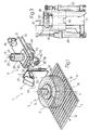
- Figure 1 shows a view in perspective, with parts removed for clarity, of a tire testing and marking unit;
- Figure 2 shows a larger-scale, partially sectioned side view of a tire marking machine forming part of the Figure 1 unit;
- Figure 3 shows a front view of a detail in Figure 2;
- Figures 4a and 4b show side views of the Figure 1 unit in two different operating positions.
-
- With reference to Figures 1 and 4,
number 1 indicates a unit for testing and markingtires 2, and comprising a known test machine (TUO) 3, and amachine 4 for markingtires 2.Machine 3 provides for making a series of measurements oftires 2, and determining, among other things, the taper vector direction and the location of the plane 5 (Figures 2 and 4b) of the radial force first harmonic (RF1H) vector; andmachine 4 cooperates withtest machine 3 to make a single mark 6 (Figures 2 and 4b) ontire 2, in plane 5 and preferably on the positive taper side, i.e. on the taper vector out side. -
Machine 3 comprises a horizontal roller conveyor 7 for successivelyfeeding tires 2, laid flat (i.e. with the axis of rotation positioned vertically), through a test andmark station 8 at whichmachine 4 is located; and two opposedcoaxial spindles vertical axis 11 and located on opposite sides of conveyor 7. Theupper spindle 9 is a powered axially-fixed spindle fitted to theoutput shaft 12 of a motor 13 (Figures 4a and 4b); and thelower spindle 10 is fitted idly to the top end of theoutput shaft 14 of a linear actuator 15 for movingspindle 10 axially back and forth through anopening 16 in conveyor 7 to lift thetire 2 instation 8 off conveyor 7 and connect it toupper spindle 9. When activated,spindle 9 rotates bothtire 2 andlower spindle 10 to enablemachine 3 to perform a series of measurements and determine, among other things, the taper and the location of the "first harmonic high point" P oftire 2. - With reference to Figure 2,
machine 4 comprises a markinghead 17; and an actuatingdevice 18 for movinghead 17 in space with respect to anadjustable assembly 19 supportingdevice 18. - Supporting
assembly 19 comprises atubular body 20 with avertical axis 21 and closed at the top by awall 22 connected integrally to afixed frame 23. Apiston 24 is housed in sliding and angularly-fixed manner insidebody 20, and is connected towall 22 by ascrew 25 extending alongaxis 21 and engaging anut screw 26 formed through anend wall 27 ofpiston 24.Screw 25 extends in rotary and axially-fixed manner throughwall 22, and comprises, overbody 20, anend coupling 28 connected to the output of amotor 29 or, according to a variation not shown, engaged by a hand tool (not shown) to adjust the axial position ofpiston 24 with respect tobody 20. - At the bottom,
piston 24 comprises anannular flange 30 connected integrally to ahorizontal guide 31 located over conveyor 7 and parallel to thetraveling direction 32 oftires 2 along conveyor 7. The bottom surface ofguide 31 is fitted with aslide 33, which is moved alongguide 31 in adirection 34 parallel todirection 32 by an actuatingdevice 35 comprising ascrew 36, which is connected in rotary and axially-fixed manner to asupport 37 integral withguide 31, and engages anut screw 38 fitted to slide 33. Actuatingdevice 35 also comprises amotor 39 fitted to guide 31, and the output of which is connected to one end ofscrew 36 to rotate it about anaxis 40 parallel todirection 34. In an embodiment not shown,motor 39 is eliminated, and the free end ofscrew 36 comprises a shank (not shown) engaged by a tool or handwheel to operatescrew 36 manually. - In addition to
guide 31,slide 33 andactuating device 35,device 18 also comprises aplate 41 located over conveyor 7 and perpendicular to conveyor 7 anddirections Plate 41 is connected integrally to one end of ashaft 42 fitted in rotary manner to slide 33 by means of twosupports 43 and forming the output shaft of amotor 44, which is fitted to slide 33 and located, together withshaft 42 and supports 43, beneathslide 33 and betweenslide 33 and conveyor 7 to rotateshaft 42 about andaxis 45 parallel todirections - With reference to Figures 2 and 3,
plate 41 forms a guide for aslide 46, which is moved alongplate 41 and in adirection 47 perpendicular toaxis 45 by alinear actuator 48 interposed betweenplate 41 andslide 46. The top end ofplate 41 opposite the end facing conveyor 7 comprises afork 49 projecting fromplate 41 towardsmachine 3 in a direction substantially parallel todirections pin 50 crosswise todirection 47.Pin 50 supportshead 17 and one end of alever 51 perpendicular topin 50 and hinged at the free end to the output member of alinear actuator 52 interposed betweenlever 51 andplate 41, and which provides for swingingpin 50 andhead 17 about anaxis 53 coaxial withpin 50. -
Head 17 comprises a markingmember 54, which, when brought substantially into contact withshoulder tire 2, provides for makingmark 6 onshoulder - In actual use, and as shown in Figures 1 and 4a,
tires 2 are fed by conveyor 7 indirection 32 and arrested, centered over opening 16, atstation 8. Thetire 2 overopening 16 is then lifted vertically byspindle 10 and connected tospindle 9, which is activated to rotate bothtire 2 andspindle 10 aboutaxis 11 to enablemachine 3 to perform the measurements provided for. - While the above operations are being performed,
machine 4 is maintained in an initial idle position in whichaxes direction 32, andhead 17 is located at a higher level thanupper shoulder 2a, is located upstream fromtire 2 indirection 32, and is separated fromaxis 11 by a distance greater than the radius oftire 2. Said idle position is set by means of an initial setting ofmachine 4, wherein the position ofpiston 24 with respect totubular body 20 is adjusted by means ofscrew 25 so thataxis 45 is substantially located in theequatorial plane 55 oftire 2. - As
tire 2 rotates betweenspindles machine 3 determines the taper vector direction and, by means of a logic control unit (not shown), controlsmachine 4 so that, beforespindle 9 is arrested,machine 4 performs a prepositioning movement depending on the sign of the detected taper vector. - In the event the taper vector is positive, i.e. directed upwards,
screw 36 is activated to movehead 17 radially forwards into an intermediate position directly over and facingshoulder 2a. Conversely, in the event the taper vector is negative, i.e. directed downwards,motor 44 is activated to rotateshaft 42 by 180° aboutaxis 45 and movehead 17 from the initial idle position into a lowered position beneath the level ofshoulder 2b oftire 2; andscrew 36 is activated to movehead 17 radially forwards into an intermediate position directly beneath and facingshoulder 2b. At this point,actuator 48 moveshead 17 axially into an operating position substantially adjacent toshoulder - When the measurements are completed,
machine 3 arrests spindle 9 so thataxis 45 extends along plane 5; andhead 17 is rotated aboutaxis 53, by the combined action ofactuator 52 andlever 51, into contact withshoulder member 54 to impressmark 6 onshoulder 2a. - Once marking is completed,
head 17 is withdrawn fromshoulder head 17 is moved clear oftire 2,tire 2 is disconnected fromspindle 9 and lowered byspindle 10 back on to conveyor 7. Obviously, in the case of a positive taper,tire 2 may be lowered on to conveyor 7 as soon as the marking operation is completed. - The marking method described affords the advantage of fully automatically impressing a
single mark 6 indicating both the taper of the tire and plane 5. Moreover, the method is implemented by amachine 4, which, by featuring various axes of movement, is capable of adapting the position ofhead 17 accurately to the contour ofshoulder tire 2. - Finally, marking
machine 4 described is extremely fast-operating, also by virtue of the possibility of synchronizing operation ofmachine 4 with that oftest machine 3.
Claims (13)
- A method of marking a tire (2) to indicate the taper vector direction and the plane (5) of the first harmonic high point (P); the tire (2) comprising a first and a second shoulder (2a, 2b); and the method being characterized by comprising a marking step wherein a single mark (6) is made on the tire (2), in said plane (5) and on one or the other of said shoulders (2a, 2b) depending on the taper vector direction.
- A method as claimed in Claim 1, characterized by also comprising the steps of feeding the tire (2), by means of a conveyor (7), in a given direction (32) to a test and mark station (8); rotating the tire (2) about a first axis (11) to determine the taper vector direction and the plane (5) of the first harmonic high point (P) of the tire (2); and arresting the tire (2) prior to application of said mark (6).
- A method as claimed in Claim 2, characterized in that said first axis (11) is a substantially vertical axis; the tire (2) being lifted off said conveyor (7) in a direction parallel to said first axis (11) before being rotated.
- A method as claimed in any one of the foregoing Claims, characterized in that said mark (6) is applied by a marking head (17) fitted to a multiple-axis device (18) for so moving the marking head (17) as to cooperate selectively with each of said shoulders (2a, 2b).
- A method as claimed in Claim 4, characterized in that the tire (2) comprises a first axis (11) of rotation; said marking head (17) being moved, in the course of said marking step, from an initial idle position wherein said marking head (17) is separated from said first axis (11) by a distance greater than a radius of said tire (2).
- A method as claimed in Claim 5, characterized in that said first axis (11) is a substantially vertical axis; said marking head (17) being located, in said initial idle position, at a higher level than the upper of said two shoulders (2a, 2b).
- A method as claimed in any one of the foregoing Claims from 4 to 6, characterized in that, prior to application of said mark (6), the tire is arrested with said plane (5) in a position in which the plane (5) faces said marking head (17).
- A method as claimed in Claim 6 or 7, characterized in that said marking step comprises the substep of translating said marking head (17), transversely with respect to said first axis (11), to and from an intermediate position facing one of said shoulders (2a, 2b).
- A method as claimed in Claim 8, characterized in that said marking head (17) is translated into said intermediate position from said initial idle position.
- A method as claimed in Claim 8, characterized in that, prior to being translated into said intermediate position, said marking head (17) is rotated about a second axis (45), crosswise to the first axis (11), from said initial idle position to a lowered position in which the marking head (17) is located at a lower level than the lower of said two shoulders (2a, 2b).
- A method as claimed in Claim 10, characterized in that said marking head (17) is translated into said intermediate position from said lowered position.
- A method as claimed in any one of the foregoing Claims from 8 to 11, characterized in that said marking step also comprises the substep of moving said marking head (17), in a direction (47) parallel to the first axis (11), between said intermediate position and an operating position substantially contacting a said shoulder (2a; 2b).
- A method as claimed in Claim 12, characterized in that said mark (6) is applied by moving said marking head (17), as of said operating position, about a third axis (53) crosswise to said first axis (11).
Applications Claiming Priority (2)
| Application Number | Priority Date | Filing Date | Title |
|---|---|---|---|
| IT96TO000972A IT1289701B1 (en) | 1996-11-29 | 1996-11-29 | METHOD FOR MARKING A TIRE |
| ITTO960972 | 1996-11-29 |
Publications (3)
| Publication Number | Publication Date |
|---|---|
| EP0845374A2 EP0845374A2 (en) | 1998-06-03 |
| EP0845374A3 EP0845374A3 (en) | 1998-12-30 |
| EP0845374B1 true EP0845374B1 (en) | 2002-02-06 |
Family
ID=11415066
Family Applications (1)
| Application Number | Title | Priority Date | Filing Date |
|---|---|---|---|
| EP97120888A Expired - Lifetime EP0845374B1 (en) | 1996-11-29 | 1997-11-27 | Tyre marking method |
Country Status (6)
| Country | Link |
|---|---|
| US (1) | US5905199A (en) |
| EP (1) | EP0845374B1 (en) |
| JP (1) | JP4028052B2 (en) |
| DE (1) | DE69710299T2 (en) |
| ES (1) | ES2170913T3 (en) |
| IT (1) | IT1289701B1 (en) |
Families Citing this family (16)
| Publication number | Priority date | Publication date | Assignee | Title |
|---|---|---|---|---|
| JPH11278020A (en) * | 1998-03-26 | 1999-10-12 | Bridgestone Corp | Marking inspecting device |
| JP2000280264A (en) | 1999-01-27 | 2000-10-10 | Bridgestone Corp | Method for correcting uniformity of tire and tire prepared by applying it |
| US6676789B1 (en) | 1999-05-20 | 2004-01-13 | The Goodyear Tire And Rubber Company | Tire building apparatus |
| WO2000072981A1 (en) * | 1999-05-27 | 2000-12-07 | The Goodyear Tire & Rubber Company | Protective paint applications to tires |
| JP4885370B2 (en) * | 2000-06-16 | 2012-02-29 | 株式会社ブリヂストン | Printing apparatus and printing method |
| ITTO20010389A1 (en) * | 2001-04-20 | 2002-10-20 | Bridgestone Firestone Tech | PLANT AND METHOD FOR THE PRODUCTION OF PMEUMATICS WITH IN-LINE CONTROL OF ELECTRIC CONDUCTIVITY. |
| JP4928105B2 (en) * | 2005-09-21 | 2012-05-09 | 住友ゴム工業株式会社 | Pneumatic tire manufacturing method and color line coating apparatus used therefor |
| JP5749946B2 (en) * | 2011-03-10 | 2015-07-15 | 株式会社ブリヂストン | Tire printing apparatus and tire surface printing method |
| JP6034759B2 (en) * | 2013-06-27 | 2016-11-30 | 株式会社神戸製鋼所 | Marking device |
| CN104260562B (en) * | 2014-10-01 | 2016-03-23 | 合肥海闻自动化设备有限公司 | A kind of tire fixture for tire digital printer |
| CN107206716A (en) * | 2015-02-05 | 2017-09-26 | 三菱重工机械科技株式会社 | tire marking device |
| DE102015217632A1 (en) * | 2015-09-15 | 2017-03-16 | Zf Friedrichshafen Ag | Method of marking a tire and device for carrying it out |
| CN105236071A (en) * | 2015-11-11 | 2016-01-13 | 万达工业(始兴)有限公司 | Automatic pad printing machine of tire |
| CN105346218A (en) * | 2015-11-11 | 2016-02-24 | 万达工业(始兴)有限公司 | Automatic pad printing machine |
| EP3238928B1 (en) * | 2016-04-28 | 2020-07-01 | 4JET Technologies GmbH | Synchronization of information on a tire |
| JP2019174449A (en) * | 2018-03-29 | 2019-10-10 | 株式会社神戸製鋼所 | Tire test machine and tire marking method |
Family Cites Families (10)
| Publication number | Priority date | Publication date | Assignee | Title |
|---|---|---|---|---|
| US1489922A (en) * | 1922-10-04 | 1924-04-08 | Miller Rubber Co | Air-bag-buffing machine |
| US1850238A (en) * | 1929-05-31 | 1932-03-22 | Fisk Rubber Co | Apparatus for spraying annular articles |
| FR1233945A (en) * | 1959-08-27 | 1960-10-13 | Hofmann K G Fa Geb | Device for characterizing tires of motor vehicles |
| US3526131A (en) * | 1968-09-09 | 1970-09-01 | Goodyear Tire & Rubber | Tire marking apparatus |
| US4260889A (en) * | 1979-11-28 | 1981-04-07 | The Firestone Tire & Rubber Company | Defect marker method and apparatus for use with tire inspection machines |
| US4308747A (en) * | 1980-03-27 | 1982-01-05 | The B. F. Goodrich Company | Apparatus for marking radial first harmonic high point on a tire |
| JPS5993343A (en) * | 1982-11-19 | 1984-05-29 | Yokohama Rubber Co Ltd:The | Marking device for tire |
| US4670289A (en) * | 1985-02-28 | 1987-06-02 | The Firestone Tire & Rubber Company | Tire marker |
| US5237505A (en) * | 1991-05-03 | 1993-08-17 | Illinois Toll Works Inc. | Method and apparatus utilizing static imbalance to reduce vibration caused by tire/wheel assemblies and tire/wheel assembly made using same |
| JP2515179B2 (en) * | 1991-03-19 | 1996-07-10 | 住友ゴム工業株式会社 | Marking device |
-
1996
- 1996-11-29 IT IT96TO000972A patent/IT1289701B1/en active IP Right Grant
-
1997
- 1997-11-20 US US08/975,178 patent/US5905199A/en not_active Expired - Lifetime
- 1997-11-26 JP JP32504597A patent/JP4028052B2/en not_active Expired - Lifetime
- 1997-11-27 EP EP97120888A patent/EP0845374B1/en not_active Expired - Lifetime
- 1997-11-27 ES ES97120888T patent/ES2170913T3/en not_active Expired - Lifetime
- 1997-11-27 DE DE69710299T patent/DE69710299T2/en not_active Expired - Lifetime
Also Published As
| Publication number | Publication date |
|---|---|
| DE69710299D1 (en) | 2002-03-21 |
| IT1289701B1 (en) | 1998-10-16 |
| ES2170913T3 (en) | 2002-08-16 |
| ITTO960972A1 (en) | 1998-05-29 |
| JPH10236116A (en) | 1998-09-08 |
| EP0845374A3 (en) | 1998-12-30 |
| EP0845374A2 (en) | 1998-06-03 |
| US5905199A (en) | 1999-05-18 |
| DE69710299T2 (en) | 2002-06-27 |
| JP4028052B2 (en) | 2007-12-26 |
Similar Documents
| Publication | Publication Date | Title |
|---|---|---|
| EP0845374B1 (en) | Tyre marking method | |
| EP0400003B1 (en) | Tire testing machine having adjustable bead width | |
| AU766962B2 (en) | Snug fitting apparatus for tire assembly | |
| JP2713708B2 (en) | Apparatus and method for grinding sidewall of tire | |
| EP1464942B1 (en) | Apparatus and method for measuring tire balance on a force variation machine | |
| US9429498B2 (en) | Tire testing machine | |
| US20050188755A1 (en) | Tire positioning sensor | |
| US3698233A (en) | Apparatus for processing cured tires | |
| CA2060109C (en) | Method and apparatus for buffing a tire sidewall | |
| US5719331A (en) | Bead width adjusting apparatus for tire uniformity machines | |
| EP0130759B1 (en) | Tire uniformity grinder | |
| US4885875A (en) | Lens edging machine and method | |
| US3656343A (en) | Apparatus for processing cured tires | |
| EP0275088B1 (en) | Tire uniformity machine and method | |
| EP0522667A1 (en) | Tire chuck | |
| JPH07243947A (en) | Runout device for tire uniformity machine | |
| JPS63281832A (en) | Manufacture of recapped tire and device therefor | |
| JPH089207B2 (en) | Automatic spew trimming method and apparatus used therefor | |
| US4768764A (en) | Green tire holder | |
| US20050000662A1 (en) | Device for optimizing bead seating | |
| JP3953200B2 (en) | Grinder skim adjustment device | |
| KR200141812Y1 (en) | Removing device for projecting part of bladder for vulcanizing tire | |
| JPH04201170A (en) | Outer surface grinding device for long shaft | |
| CN113405430A (en) | Detection tool and detection method for fit clearance between upper roller and lower roller of rim forming roller | |
| KR20030054031A (en) | Roll Grinder |
Legal Events
| Date | Code | Title | Description |
|---|---|---|---|
| PUAI | Public reference made under article 153(3) epc to a published international application that has entered the european phase |
Free format text: ORIGINAL CODE: 0009012 |
|
| AK | Designated contracting states |
Kind code of ref document: A2 Designated state(s): DE ES FR IT |
|
| AX | Request for extension of the european patent |
Free format text: AL;LT;LV;MK;RO;SI |
|
| PUAL | Search report despatched |
Free format text: ORIGINAL CODE: 0009013 |
|
| AK | Designated contracting states |
Kind code of ref document: A3 Designated state(s): AT BE CH DE DK ES FI FR GB GR IE IT LI LU MC NL PT SE |
|
| AX | Request for extension of the european patent |
Free format text: AL;LT;LV;MK;RO;SI |
|
| 17P | Request for examination filed |
Effective date: 19990628 |
|
| AKX | Designation fees paid |
Free format text: DE ES FR IT |
|
| GRAG | Despatch of communication of intention to grant |
Free format text: ORIGINAL CODE: EPIDOS AGRA |
|
| 17Q | First examination report despatched |
Effective date: 20010605 |
|
| GRAG | Despatch of communication of intention to grant |
Free format text: ORIGINAL CODE: EPIDOS AGRA |
|
| GRAH | Despatch of communication of intention to grant a patent |
Free format text: ORIGINAL CODE: EPIDOS IGRA |
|
| GRAH | Despatch of communication of intention to grant a patent |
Free format text: ORIGINAL CODE: EPIDOS IGRA |
|
| GRAA | (expected) grant |
Free format text: ORIGINAL CODE: 0009210 |
|
| AK | Designated contracting states |
Kind code of ref document: B1 Designated state(s): DE ES FR IT |
|
| REF | Corresponds to: |
Ref document number: 69710299 Country of ref document: DE Date of ref document: 20020321 |
|
| ET | Fr: translation filed | ||
| REG | Reference to a national code |
Ref country code: ES Ref legal event code: FG2A Ref document number: 2170913 Country of ref document: ES Kind code of ref document: T3 |
|
| PLBE | No opposition filed within time limit |
Free format text: ORIGINAL CODE: 0009261 |
|
| STAA | Information on the status of an ep patent application or granted ep patent |
Free format text: STATUS: NO OPPOSITION FILED WITHIN TIME LIMIT |
|
| 26N | No opposition filed |
Effective date: 20021107 |
|
| REG | Reference to a national code |
Ref country code: DE Ref legal event code: R082 Ref document number: 69710299 Country of ref document: DE Representative=s name: KRAUS & WEISERT PATENTANWAELTE PARTGMBB, DE |
|
| REG | Reference to a national code |
Ref country code: FR Ref legal event code: CA Effective date: 20140812 |
|
| REG | Reference to a national code |
Ref country code: DE Ref legal event code: R082 Ref document number: 69710299 Country of ref document: DE Representative=s name: KRAUS & WEISERT PATENTANWAELTE PARTGMBB, DE Effective date: 20140828 Ref country code: DE Ref legal event code: R081 Ref document number: 69710299 Country of ref document: DE Owner name: BRIDGESTONE CORPORATION, JP Free format text: FORMER OWNER: BRIDGESTONE CORP., TOKIO/TOKYO, JP Effective date: 20140828 |
|
| REG | Reference to a national code |
Ref country code: FR Ref legal event code: PLFP Year of fee payment: 19 |
|
| REG | Reference to a national code |
Ref country code: FR Ref legal event code: PLFP Year of fee payment: 20 |
|
| PGFP | Annual fee paid to national office [announced via postgrant information from national office to epo] |
Ref country code: FR Payment date: 20161118 Year of fee payment: 20 Ref country code: DE Payment date: 20161121 Year of fee payment: 20 |
|
| PGFP | Annual fee paid to national office [announced via postgrant information from national office to epo] |
Ref country code: IT Payment date: 20161123 Year of fee payment: 20 Ref country code: ES Payment date: 20161114 Year of fee payment: 20 |
|
| REG | Reference to a national code |
Ref country code: DE Ref legal event code: R071 Ref document number: 69710299 Country of ref document: DE |
|
| REG | Reference to a national code |
Ref country code: ES Ref legal event code: FD2A Effective date: 20180508 |
|
| PG25 | Lapsed in a contracting state [announced via postgrant information from national office to epo] |
Ref country code: ES Free format text: LAPSE BECAUSE OF EXPIRATION OF PROTECTION Effective date: 20171128 |