EP0845366B1 - Tintenstrahldruckverfahren, Tintenstrahldruckapparat für dieses Verfahren und durch dieses Verfahren hergestelltes Druckerzeugnis - Google Patents
Tintenstrahldruckverfahren, Tintenstrahldruckapparat für dieses Verfahren und durch dieses Verfahren hergestelltes Druckerzeugnis Download PDFInfo
- Publication number
- EP0845366B1 EP0845366B1 EP97121068A EP97121068A EP0845366B1 EP 0845366 B1 EP0845366 B1 EP 0845366B1 EP 97121068 A EP97121068 A EP 97121068A EP 97121068 A EP97121068 A EP 97121068A EP 0845366 B1 EP0845366 B1 EP 0845366B1
- Authority
- EP
- European Patent Office
- Prior art keywords
- image
- ink
- printing
- preservation
- Prior art date
- Legal status (The legal status is an assumption and is not a legal conclusion. Google has not performed a legal analysis and makes no representation as to the accuracy of the status listed.)
- Expired - Lifetime
Links
- 238000000034 method Methods 0.000 title claims description 38
- 238000004321 preservation Methods 0.000 claims description 40
- 239000000463 material Substances 0.000 claims description 28
- PNEYBMLMFCGWSK-UHFFFAOYSA-N aluminium oxide Inorganic materials [O-2].[O-2].[O-2].[Al+3].[Al+3] PNEYBMLMFCGWSK-UHFFFAOYSA-N 0.000 claims description 24
- 238000007639 printing Methods 0.000 claims description 22
- 238000004040 coloring Methods 0.000 claims description 18
- 238000007599 discharging Methods 0.000 claims description 18
- 230000003287 optical effect Effects 0.000 claims description 12
- VYPSYNLAJGMNEJ-UHFFFAOYSA-N Silicium dioxide Chemical compound O=[Si]=O VYPSYNLAJGMNEJ-UHFFFAOYSA-N 0.000 claims description 7
- 239000000377 silicon dioxide Substances 0.000 claims description 3
- VXAUWWUXCIMFIM-UHFFFAOYSA-M aluminum;oxygen(2-);hydroxide Chemical compound [OH-].[O-2].[Al+3] VXAUWWUXCIMFIM-UHFFFAOYSA-M 0.000 claims description 2
- 238000001514 detection method Methods 0.000 claims description 2
- 238000002834 transmittance Methods 0.000 claims 1
- 239000000976 ink Substances 0.000 description 75
- 239000002253 acid Substances 0.000 description 20
- LYCAIKOWRPUZTN-UHFFFAOYSA-N Ethylene glycol Chemical compound OCCO LYCAIKOWRPUZTN-UHFFFAOYSA-N 0.000 description 19
- 239000000049 pigment Substances 0.000 description 19
- 239000000975 dye Substances 0.000 description 18
- 239000007787 solid Substances 0.000 description 14
- 230000006866 deterioration Effects 0.000 description 13
- FPVGTPBMTFTMRT-UHFFFAOYSA-L disodium;2-amino-5-[(4-sulfonatophenyl)diazenyl]benzenesulfonate Chemical compound [Na+].[Na+].C1=C(S([O-])(=O)=O)C(N)=CC=C1N=NC1=CC=C(S([O-])(=O)=O)C=C1 FPVGTPBMTFTMRT-UHFFFAOYSA-L 0.000 description 11
- 235000019233 fast yellow AB Nutrition 0.000 description 11
- 239000012530 fluid Substances 0.000 description 11
- 235000019241 carbon black Nutrition 0.000 description 10
- FAHBNUUHRFUEAI-UHFFFAOYSA-M hydroxidooxidoaluminium Chemical group O[Al]=O FAHBNUUHRFUEAI-UHFFFAOYSA-M 0.000 description 10
- XSQUKJJJFZCRTK-UHFFFAOYSA-N Urea Chemical compound NC(N)=O XSQUKJJJFZCRTK-UHFFFAOYSA-N 0.000 description 9
- 239000004816 latex Substances 0.000 description 9
- 229920000126 latex Polymers 0.000 description 9
- XLYOFNOQVPJJNP-UHFFFAOYSA-N water Substances O XLYOFNOQVPJJNP-UHFFFAOYSA-N 0.000 description 9
- PEDCQBHIVMGVHV-UHFFFAOYSA-N Glycerine Chemical compound OCC(O)CO PEDCQBHIVMGVHV-UHFFFAOYSA-N 0.000 description 8
- 239000004372 Polyvinyl alcohol Substances 0.000 description 7
- 229910052782 aluminium Inorganic materials 0.000 description 7
- 239000003795 chemical substances by application Substances 0.000 description 7
- -1 ethylene glycol monoalkylether Chemical class 0.000 description 7
- 238000002156 mixing Methods 0.000 description 7
- 229920002451 polyvinyl alcohol Polymers 0.000 description 7
- 239000011230 binding agent Substances 0.000 description 6
- 238000010438 heat treatment Methods 0.000 description 6
- 230000032683 aging Effects 0.000 description 5
- XAGFODPZIPBFFR-UHFFFAOYSA-N aluminium Chemical compound [Al] XAGFODPZIPBFFR-UHFFFAOYSA-N 0.000 description 5
- 239000011248 coating agent Substances 0.000 description 5
- 238000000576 coating method Methods 0.000 description 5
- 238000003745 diagnosis Methods 0.000 description 5
- 239000006185 dispersion Substances 0.000 description 5
- 238000005342 ion exchange Methods 0.000 description 5
- 238000003860 storage Methods 0.000 description 5
- 239000006096 absorbing agent Substances 0.000 description 4
- 239000004202 carbamide Substances 0.000 description 4
- 229920001577 copolymer Polymers 0.000 description 4
- UZZFFIUHUDOYPS-UHFFFAOYSA-L disodium 4-amino-3,6-bis[[4-[(2,4-diaminophenyl)diazenyl]phenyl]diazenyl]-5-oxido-7-sulfonaphthalene-2-sulfonate Chemical compound [Na+].[Na+].Nc1ccc(N=Nc2ccc(cc2)N=Nc2c(N)c3c(O)c(N=Nc4ccc(cc4)N=Nc4ccc(N)cc4N)c(cc3cc2S([O-])(=O)=O)S([O-])(=O)=O)c(N)c1 UZZFFIUHUDOYPS-UHFFFAOYSA-L 0.000 description 4
- 239000002270 dispersing agent Substances 0.000 description 4
- 235000011187 glycerol Nutrition 0.000 description 4
- 238000005259 measurement Methods 0.000 description 4
- 239000003960 organic solvent Substances 0.000 description 4
- 239000002002 slurry Substances 0.000 description 4
- GGCZERPQGJTIQP-UHFFFAOYSA-N sodium;9,10-dioxoanthracene-2-sulfonic acid Chemical compound [Na+].C1=CC=C2C(=O)C3=CC(S(=O)(=O)O)=CC=C3C(=O)C2=C1 GGCZERPQGJTIQP-UHFFFAOYSA-N 0.000 description 4
- 239000002904 solvent Substances 0.000 description 4
- 239000004094 surface-active agent Substances 0.000 description 4
- LFQSCWFLJHTTHZ-UHFFFAOYSA-N Ethanol Chemical compound CCO LFQSCWFLJHTTHZ-UHFFFAOYSA-N 0.000 description 3
- 108010010803 Gelatin Proteins 0.000 description 3
- OKKJLVBELUTLKV-UHFFFAOYSA-N Methanol Chemical compound OC OKKJLVBELUTLKV-UHFFFAOYSA-N 0.000 description 3
- 229920002472 Starch Polymers 0.000 description 3
- GWEVSGVZZGPLCZ-UHFFFAOYSA-N Titan oxide Chemical compound O=[Ti]=O GWEVSGVZZGPLCZ-UHFFFAOYSA-N 0.000 description 3
- 150000004703 alkoxides Chemical class 0.000 description 3
- 239000000981 basic dye Substances 0.000 description 3
- 238000009835 boiling Methods 0.000 description 3
- 239000006229 carbon black Substances 0.000 description 3
- 239000005018 casein Substances 0.000 description 3
- BECPQYXYKAMYBN-UHFFFAOYSA-N casein, tech. Chemical compound NCCCCC(C(O)=O)N=C(O)C(CC(O)=O)N=C(O)C(CCC(O)=N)N=C(O)C(CC(C)C)N=C(O)C(CCC(O)=O)N=C(O)C(CC(O)=O)N=C(O)C(CCC(O)=O)N=C(O)C(C(C)O)N=C(O)C(CCC(O)=N)N=C(O)C(CCC(O)=N)N=C(O)C(CCC(O)=N)N=C(O)C(CCC(O)=O)N=C(O)C(CCC(O)=O)N=C(O)C(COP(O)(O)=O)N=C(O)C(CCC(O)=N)N=C(O)C(N)CC1=CC=CC=C1 BECPQYXYKAMYBN-UHFFFAOYSA-N 0.000 description 3
- 235000021240 caseins Nutrition 0.000 description 3
- 239000003086 colorant Substances 0.000 description 3
- 238000004925 denaturation Methods 0.000 description 3
- 230000036425 denaturation Effects 0.000 description 3
- MTHSVFCYNBDYFN-UHFFFAOYSA-N diethylene glycol Chemical compound OCCOCCO MTHSVFCYNBDYFN-UHFFFAOYSA-N 0.000 description 3
- 238000001035 drying Methods 0.000 description 3
- 230000000694 effects Effects 0.000 description 3
- 239000008273 gelatin Substances 0.000 description 3
- 229920000159 gelatin Polymers 0.000 description 3
- 235000019322 gelatine Nutrition 0.000 description 3
- 235000011852 gelatine desserts Nutrition 0.000 description 3
- 238000004519 manufacturing process Methods 0.000 description 3
- 230000001590 oxidative effect Effects 0.000 description 3
- 239000011148 porous material Substances 0.000 description 3
- 235000019698 starch Nutrition 0.000 description 3
- 239000008107 starch Substances 0.000 description 3
- GWAKFAUFNNPZFE-UHFFFAOYSA-K trisodium 2-[4-[(2-amino-4-oxidophenyl)diazenyl]anilino]-5-[(1-amino-8-oxido-7-phenyldiazenyl-3,6-disulfonaphthalen-2-yl)diazenyl]benzenesulfonate Chemical compound NC1=C(C(=CC2=CC(=C(C(=C12)O)N=NC1=CC=CC=C1)S(=O)(=O)[O-])S(=O)(=O)[O-])N=NC1=CC(=C(C=C1)NC1=CC=C(C=C1)N=NC1=C(C=C(C=C1)O)N)S(=O)(=O)[O-].[Na+].[Na+].[Na+] GWAKFAUFNNPZFE-UHFFFAOYSA-K 0.000 description 3
- ZNQVEEAIQZEUHB-UHFFFAOYSA-N 2-ethoxyethanol Chemical compound CCOCCO ZNQVEEAIQZEUHB-UHFFFAOYSA-N 0.000 description 2
- KFZMGEQAYNKOFK-UHFFFAOYSA-N Isopropanol Chemical compound CC(C)O KFZMGEQAYNKOFK-UHFFFAOYSA-N 0.000 description 2
- LRHPLDYGYMQRHN-UHFFFAOYSA-N N-Butanol Chemical compound CCCCO LRHPLDYGYMQRHN-UHFFFAOYSA-N 0.000 description 2
- SECXISVLQFMRJM-UHFFFAOYSA-N N-Methylpyrrolidone Chemical compound CN1CCCC1=O SECXISVLQFMRJM-UHFFFAOYSA-N 0.000 description 2
- 239000004698 Polyethylene Substances 0.000 description 2
- 238000002441 X-ray diffraction Methods 0.000 description 2
- 150000001298 alcohols Chemical class 0.000 description 2
- 150000001450 anions Chemical class 0.000 description 2
- 239000002518 antifoaming agent Substances 0.000 description 2
- 239000004599 antimicrobial Substances 0.000 description 2
- 239000003963 antioxidant agent Substances 0.000 description 2
- 230000003078 antioxidant effect Effects 0.000 description 2
- 125000004432 carbon atom Chemical group C* 0.000 description 2
- 238000010276 construction Methods 0.000 description 2
- ZXJXZNDDNMQXFV-UHFFFAOYSA-M crystal violet Chemical compound [Cl-].C1=CC(N(C)C)=CC=C1[C+](C=1C=CC(=CC=1)N(C)C)C1=CC=C(N(C)C)C=C1 ZXJXZNDDNMQXFV-UHFFFAOYSA-M 0.000 description 2
- 230000007423 decrease Effects 0.000 description 2
- 230000002950 deficient Effects 0.000 description 2
- 238000010586 diagram Methods 0.000 description 2
- 150000001993 dienes Chemical class 0.000 description 2
- 239000000982 direct dye Substances 0.000 description 2
- 239000011521 glass Substances 0.000 description 2
- 239000003906 humectant Substances 0.000 description 2
- ZXEKIIBDNHEJCQ-UHFFFAOYSA-N isobutanol Chemical compound CC(C)CO ZXEKIIBDNHEJCQ-UHFFFAOYSA-N 0.000 description 2
- 239000007788 liquid Substances 0.000 description 2
- 230000003647 oxidation Effects 0.000 description 2
- 238000007254 oxidation reaction Methods 0.000 description 2
- 229920003023 plastic Polymers 0.000 description 2
- 239000004033 plastic Substances 0.000 description 2
- 239000004417 polycarbonate Substances 0.000 description 2
- 229920000515 polycarbonate Polymers 0.000 description 2
- 229920000728 polyester Polymers 0.000 description 2
- 229920000573 polyethylene Polymers 0.000 description 2
- 229920000642 polymer Polymers 0.000 description 2
- 239000011347 resin Substances 0.000 description 2
- 229920005989 resin Polymers 0.000 description 2
- 239000000126 substance Substances 0.000 description 2
- 150000003866 tertiary ammonium salts Chemical class 0.000 description 2
- 229920001169 thermoplastic Polymers 0.000 description 2
- 239000004416 thermosoftening plastic Substances 0.000 description 2
- UMGDCJDMYOKAJW-UHFFFAOYSA-N thiourea Chemical compound NC(N)=S UMGDCJDMYOKAJW-UHFFFAOYSA-N 0.000 description 2
- 125000000391 vinyl group Chemical group [H]C([*])=C([H])[H] 0.000 description 2
- 229920002554 vinyl polymer Polymers 0.000 description 2
- JNYAEWCLZODPBN-JGWLITMVSA-N (2r,3r,4s)-2-[(1r)-1,2-dihydroxyethyl]oxolane-3,4-diol Chemical compound OC[C@@H](O)[C@H]1OC[C@H](O)[C@H]1O JNYAEWCLZODPBN-JGWLITMVSA-N 0.000 description 1
- DSZCWNRVMXBILR-UHFFFAOYSA-M (2z)-1,3,3-trimethyl-2-[2-(2-methyl-2,3-dihydroindol-1-ium-1-ylidene)ethylidene]indole;chloride Chemical compound [Cl-].CN/1C2=CC=CC=C2C(C)(C)C\1=C/C=[N+]1C2=CC=CC=C2CC1C DSZCWNRVMXBILR-UHFFFAOYSA-M 0.000 description 1
- MCTQNEBFZMBRSQ-UHFFFAOYSA-N (3-amino-4-phenyldiazenylphenyl)azanium;chloride Chemical compound Cl.NC1=CC(N)=CC=C1N=NC1=CC=CC=C1 MCTQNEBFZMBRSQ-UHFFFAOYSA-N 0.000 description 1
- KMZHZAAOEWVPSE-UHFFFAOYSA-N 2,3-dihydroxypropyl acetate Chemical compound CC(=O)OCC(O)CO KMZHZAAOEWVPSE-UHFFFAOYSA-N 0.000 description 1
- SIWFBKUKQZOOAO-UHFFFAOYSA-N 2,5-dichloro-4-[4-[(4-dodecylphenyl)diazenyl]-3-methyl-5-oxo-4h-pyrazol-1-yl]benzenesulfonic acid Chemical compound C1=CC(CCCCCCCCCCCC)=CC=C1N=NC1C(=O)N(C=2C(=CC(=C(Cl)C=2)S(O)(=O)=O)Cl)N=C1C SIWFBKUKQZOOAO-UHFFFAOYSA-N 0.000 description 1
- POAOYUHQDCAZBD-UHFFFAOYSA-N 2-butoxyethanol Chemical compound CCCCOCCO POAOYUHQDCAZBD-UHFFFAOYSA-N 0.000 description 1
- UPZFLZYXYGBAPL-UHFFFAOYSA-N 2-ethyl-2-methyl-1,3-dioxolane Chemical compound CCC1(C)OCCO1 UPZFLZYXYGBAPL-UHFFFAOYSA-N 0.000 description 1
- NJIRSTSECXKPCO-UHFFFAOYSA-M 3-[n-methyl-4-[2-(1,3,3-trimethylindol-1-ium-2-yl)ethenyl]anilino]propanenitrile;chloride Chemical compound [Cl-].C1=CC(N(CCC#N)C)=CC=C1\C=C\C1=[N+](C)C2=CC=CC=C2C1(C)C NJIRSTSECXKPCO-UHFFFAOYSA-M 0.000 description 1
- QHVBDWZOQBMLLW-UHFFFAOYSA-N 4-[(5-amino-3-methyl-1-phenylpyrazol-4-yl)diazenyl]-2,5-dichlorobenzenesulfonic acid Chemical compound NC1=C(C(=NN1C1=CC=CC=C1)C)N=NC1=C(C=C(C(=C1)Cl)S(=O)(=O)O)Cl QHVBDWZOQBMLLW-UHFFFAOYSA-N 0.000 description 1
- CNGYZEMWVAWWOB-VAWYXSNFSA-N 5-[[4-anilino-6-[bis(2-hydroxyethyl)amino]-1,3,5-triazin-2-yl]amino]-2-[(e)-2-[4-[[4-anilino-6-[bis(2-hydroxyethyl)amino]-1,3,5-triazin-2-yl]amino]-2-sulfophenyl]ethenyl]benzenesulfonic acid Chemical compound N=1C(NC=2C=C(C(\C=C\C=3C(=CC(NC=4N=C(N=C(NC=5C=CC=CC=5)N=4)N(CCO)CCO)=CC=3)S(O)(=O)=O)=CC=2)S(O)(=O)=O)=NC(N(CCO)CCO)=NC=1NC1=CC=CC=C1 CNGYZEMWVAWWOB-VAWYXSNFSA-N 0.000 description 1
- RJZLMBIYRSBCDQ-UHFFFAOYSA-N 6-amino-5-[[2-[ethyl(phenyl)sulfamoyl]phenyl]diazenyl]-4-hydroxynaphthalene-2-sulfonic acid Chemical compound CCN(C1=CC=CC=C1)S(=O)(=O)C1=CC=CC=C1N=NC1=C(N)C=CC2=C1C(O)=CC(=C2)S(O)(=O)=O RJZLMBIYRSBCDQ-UHFFFAOYSA-N 0.000 description 1
- 244000215068 Acacia senegal Species 0.000 description 1
- WLDHEUZGFKACJH-ZRUFZDNISA-K Amaranth Chemical compound [Na+].[Na+].[Na+].C12=CC=C(S([O-])(=O)=O)C=C2C=C(S([O-])(=O)=O)C(O)=C1\N=N\C1=CC=C(S([O-])(=O)=O)C2=CC=CC=C12 WLDHEUZGFKACJH-ZRUFZDNISA-K 0.000 description 1
- AOMZHDJXSYHPKS-DROYEMJCSA-L Amido Black 10B Chemical compound [Na+].[Na+].[O-]S(=O)(=O)C1=CC2=CC(S([O-])(=O)=O)=C(\N=N\C=3C=CC=CC=3)C(O)=C2C(N)=C1\N=N\C1=CC=C(N(=O)=O)C=C1 AOMZHDJXSYHPKS-DROYEMJCSA-L 0.000 description 1
- SGHZXLIDFTYFHQ-UHFFFAOYSA-L Brilliant Blue Chemical compound [Na+].[Na+].C=1C=C(C(=C2C=CC(C=C2)=[N+](CC)CC=2C=C(C=CC=2)S([O-])(=O)=O)C=2C(=CC=CC=2)S([O-])(=O)=O)C=CC=1N(CC)CC1=CC=CC(S([O-])(=O)=O)=C1 SGHZXLIDFTYFHQ-UHFFFAOYSA-L 0.000 description 1
- RTMBGDBBDQKNNZ-UHFFFAOYSA-L C.I. Acid Blue 3 Chemical compound [Ca+2].C1=CC(N(CC)CC)=CC=C1C(C=1C(=CC(=C(O)C=1)S([O-])(=O)=O)S([O-])(=O)=O)=C1C=CC(=[N+](CC)CC)C=C1.C1=CC(N(CC)CC)=CC=C1C(C=1C(=CC(=C(O)C=1)S([O-])(=O)=O)S([O-])(=O)=O)=C1C=CC(=[N+](CC)CC)C=C1 RTMBGDBBDQKNNZ-UHFFFAOYSA-L 0.000 description 1
- JUQPZRLQQYSMEQ-UHFFFAOYSA-N CI Basic red 9 Chemical compound [Cl-].C1=CC(N)=CC=C1C(C=1C=CC(N)=CC=1)=C1C=CC(=[NH2+])C=C1 JUQPZRLQQYSMEQ-UHFFFAOYSA-N 0.000 description 1
- 239000005997 Calcium carbide Substances 0.000 description 1
- 229920002134 Carboxymethyl cellulose Polymers 0.000 description 1
- 108010076119 Caseins Proteins 0.000 description 1
- 229920001661 Chitosan Polymers 0.000 description 1
- FBPFZTCFMRRESA-FSIIMWSLSA-N D-Glucitol Natural products OC[C@H](O)[C@H](O)[C@@H](O)[C@H](O)CO FBPFZTCFMRRESA-FSIIMWSLSA-N 0.000 description 1
- FBPFZTCFMRRESA-JGWLITMVSA-N D-glucitol Chemical compound OC[C@H](O)[C@@H](O)[C@H](O)[C@H](O)CO FBPFZTCFMRRESA-JGWLITMVSA-N 0.000 description 1
- LCGLNKUTAGEVQW-UHFFFAOYSA-N Dimethyl ether Chemical compound COC LCGLNKUTAGEVQW-UHFFFAOYSA-N 0.000 description 1
- XKTMIJODWOEBKO-UHFFFAOYSA-M Guinee green B Chemical compound [Na+].C=1C=C(C(=C2C=CC(C=C2)=[N+](CC)CC=2C=C(C=CC=2)S([O-])(=O)=O)C=2C=CC=CC=2)C=CC=1N(CC)CC1=CC=CC(S([O-])(=O)=O)=C1 XKTMIJODWOEBKO-UHFFFAOYSA-M 0.000 description 1
- 229920000084 Gum arabic Polymers 0.000 description 1
- 239000004354 Hydroxyethyl cellulose Substances 0.000 description 1
- 229920000663 Hydroxyethyl cellulose Polymers 0.000 description 1
- 229910002651 NO3 Inorganic materials 0.000 description 1
- NHNBFGGVMKEFGY-UHFFFAOYSA-N Nitrate Chemical compound [O-][N+]([O-])=O NHNBFGGVMKEFGY-UHFFFAOYSA-N 0.000 description 1
- 241000047703 Nonion Species 0.000 description 1
- SJEYSFABYSGQBG-UHFFFAOYSA-M Patent blue Chemical compound [Na+].C1=CC(N(CC)CC)=CC=C1C(C=1C(=CC(=CC=1)S([O-])(=O)=O)S([O-])(=O)=O)=C1C=CC(=[N+](CC)CC)C=C1 SJEYSFABYSGQBG-UHFFFAOYSA-M 0.000 description 1
- 239000004743 Polypropylene Substances 0.000 description 1
- 239000004793 Polystyrene Substances 0.000 description 1
- 241001074085 Scophthalmus aquosus Species 0.000 description 1
- UFUQRRYHIHJMPB-DUCFOALUSA-L Sirius red 4B Chemical compound [Na+].[Na+].OS(=O)(=O)c1cc2cc(NC(=O)c3ccccc3)ccc2c([O-])c1\N=N\c1ccc(cc1)\N=N\c1ccc(cc1)S([O-])(=O)=O UFUQRRYHIHJMPB-DUCFOALUSA-L 0.000 description 1
- YIQKLZYTHXTDDT-UHFFFAOYSA-H Sirius red F3B Chemical compound C1=CC(=CC=C1N=NC2=CC(=C(C=C2)N=NC3=C(C=C4C=C(C=CC4=C3[O-])NC(=O)NC5=CC6=CC(=C(C(=C6C=C5)[O-])N=NC7=C(C=C(C=C7)N=NC8=CC=C(C=C8)S(=O)(=O)[O-])S(=O)(=O)[O-])S(=O)(=O)O)S(=O)(=O)O)S(=O)(=O)[O-])S(=O)(=O)[O-].[Na+].[Na+].[Na+].[Na+].[Na+].[Na+] YIQKLZYTHXTDDT-UHFFFAOYSA-H 0.000 description 1
- 108010073771 Soybean Proteins Proteins 0.000 description 1
- 229910021536 Zeolite Inorganic materials 0.000 description 1
- UXEAWNJALIUYRH-UHFFFAOYSA-N [8-[(4-aminophenyl)hydrazinylidene]-7-oxonaphthalen-2-yl]-trimethylazanium;chloride Chemical compound [Cl-].C12=CC([N+](C)(C)C)=CC=C2C=CC(=O)\C1=N/NC1=CC=C(N)C=C1 UXEAWNJALIUYRH-UHFFFAOYSA-N 0.000 description 1
- 239000002250 absorbent Substances 0.000 description 1
- 230000002745 absorbent Effects 0.000 description 1
- 239000000205 acacia gum Substances 0.000 description 1
- 235000010489 acacia gum Nutrition 0.000 description 1
- 229940019789 acid black 52 Drugs 0.000 description 1
- LIKZXCROQGHXTI-UHFFFAOYSA-M acid blue 25 Chemical compound [Na+].C1=2C(=O)C3=CC=CC=C3C(=O)C=2C(N)=C(S([O-])(=O)=O)C=C1NC1=CC=CC=C1 LIKZXCROQGHXTI-UHFFFAOYSA-M 0.000 description 1
- YJVBLROMQZEFPA-UHFFFAOYSA-L acid red 26 Chemical compound [Na+].[Na+].CC1=CC(C)=CC=C1N=NC1=C(O)C(S([O-])(=O)=O)=CC2=CC(S([O-])(=O)=O)=CC=C12 YJVBLROMQZEFPA-UHFFFAOYSA-L 0.000 description 1
- NIXOWILDQLNWCW-UHFFFAOYSA-N acrylic acid group Chemical group C(C=C)(=O)O NIXOWILDQLNWCW-UHFFFAOYSA-N 0.000 description 1
- 230000007059 acute toxicity Effects 0.000 description 1
- 231100000403 acute toxicity Toxicity 0.000 description 1
- 239000000654 additive Substances 0.000 description 1
- 229940037003 alum Drugs 0.000 description 1
- 235000012735 amaranth Nutrition 0.000 description 1
- 230000002421 anti-septic effect Effects 0.000 description 1
- 239000003429 antifungal agent Substances 0.000 description 1
- 229940121375 antifungal agent Drugs 0.000 description 1
- 239000008346 aqueous phase Substances 0.000 description 1
- KSCQDDRPFHTIRL-UHFFFAOYSA-N auramine O Chemical compound [H+].[Cl-].C1=CC(N(C)C)=CC=C1C(=N)C1=CC=C(N(C)C)C=C1 KSCQDDRPFHTIRL-UHFFFAOYSA-N 0.000 description 1
- 235000012733 azorubine Nutrition 0.000 description 1
- 229910052788 barium Inorganic materials 0.000 description 1
- DSAJWYNOEDNPEQ-UHFFFAOYSA-N barium atom Chemical compound [Ba] DSAJWYNOEDNPEQ-UHFFFAOYSA-N 0.000 description 1
- VJDDAARZIFHSQY-UHFFFAOYSA-N basic black 2 Chemical compound [Cl-].C=1C2=[N+](C=3C=CC=CC=3)C3=CC(N(CC)CC)=CC=C3N=C2C=CC=1NN=C1C=CC(=O)C=C1 VJDDAARZIFHSQY-UHFFFAOYSA-N 0.000 description 1
- 230000005540 biological transmission Effects 0.000 description 1
- 230000015572 biosynthetic process Effects 0.000 description 1
- 235000012745 brilliant blue FCF Nutrition 0.000 description 1
- 239000004161 brilliant blue FCF Substances 0.000 description 1
- 229910052793 cadmium Inorganic materials 0.000 description 1
- BDOSMKKIYDKNTQ-UHFFFAOYSA-N cadmium atom Chemical compound [Cd] BDOSMKKIYDKNTQ-UHFFFAOYSA-N 0.000 description 1
- 239000001768 carboxy methyl cellulose Substances 0.000 description 1
- 235000010948 carboxy methyl cellulose Nutrition 0.000 description 1
- 239000008112 carboxymethyl-cellulose Substances 0.000 description 1
- 125000002091 cationic group Chemical group 0.000 description 1
- 150000001768 cations Chemical class 0.000 description 1
- 239000001913 cellulose Substances 0.000 description 1
- 229920002678 cellulose Polymers 0.000 description 1
- 229920002301 cellulose acetate Polymers 0.000 description 1
- 239000000919 ceramic Substances 0.000 description 1
- IWWWBRIIGAXLCJ-BGABXYSRSA-N chembl1185241 Chemical compound C1=2C=C(C)C(NCC)=CC=2OC2=C\C(=N/CC)C(C)=CC2=C1C1=CC=CC=C1C(=O)OCC IWWWBRIIGAXLCJ-BGABXYSRSA-N 0.000 description 1
- NLMHXPDMNXMQBY-UHFFFAOYSA-L chembl260999 Chemical compound [Na+].[Na+].C1=CC(NC(=O)C)=CC=C1N=NC(C(=CC1=C2)S([O-])(=O)=O)=C(O)C1=CC=C2NC(=O)NC1=CC=C(C(O)=C(N=NC=2C=CC=CC=2)C(=C2)S([O-])(=O)=O)C2=C1 NLMHXPDMNXMQBY-UHFFFAOYSA-L 0.000 description 1
- BPHHNXJPFPEJOF-UHFFFAOYSA-J chembl296966 Chemical compound [Na+].[Na+].[Na+].[Na+].[O-]S(=O)(=O)C1=CC(S([O-])(=O)=O)=C(N)C2=C(O)C(N=NC3=CC=C(C=C3OC)C=3C=C(C(=CC=3)N=NC=3C(=C4C(N)=C(C=C(C4=CC=3)S([O-])(=O)=O)S([O-])(=O)=O)O)OC)=CC=C21 BPHHNXJPFPEJOF-UHFFFAOYSA-J 0.000 description 1
- XRPLBRIHZGVJIC-UHFFFAOYSA-L chembl3182776 Chemical compound [Na+].[Na+].NC1=CC(N)=CC=C1N=NC1=CC=C(C=2C=CC(=CC=2)N=NC=2C(=CC3=CC(=C(N=NC=4C=CC=CC=4)C(O)=C3C=2N)S([O-])(=O)=O)S([O-])(=O)=O)C=C1 XRPLBRIHZGVJIC-UHFFFAOYSA-L 0.000 description 1
- 238000004140 cleaning Methods 0.000 description 1
- 150000001875 compounds Chemical class 0.000 description 1
- 239000000470 constituent Substances 0.000 description 1
- 230000008602 contraction Effects 0.000 description 1
- NKLPQNGYXWVELD-UHFFFAOYSA-M coomassie brilliant blue Chemical compound [Na+].C1=CC(OCC)=CC=C1NC1=CC=C(C(=C2C=CC(C=C2)=[N+](CC)CC=2C=C(C=CC=2)S([O-])(=O)=O)C=2C=CC(=CC=2)N(CC)CC=2C=C(C=CC=2)S([O-])(=O)=O)C=C1 NKLPQNGYXWVELD-UHFFFAOYSA-M 0.000 description 1
- 238000012937 correction Methods 0.000 description 1
- 230000007797 corrosion Effects 0.000 description 1
- 238000005260 corrosion Methods 0.000 description 1
- 238000005336 cracking Methods 0.000 description 1
- 230000003247 decreasing effect Effects 0.000 description 1
- 239000003398 denaturant Substances 0.000 description 1
- 230000001419 dependent effect Effects 0.000 description 1
- 238000011161 development Methods 0.000 description 1
- 230000018109 developmental process Effects 0.000 description 1
- VADJQOXWNSPOQA-UHFFFAOYSA-L dichlorozinc;3-n,3-n,6-n,6-n-tetramethylacridine-3,6-diamine;hydrochloride Chemical compound Cl.[Cl-].[Cl-].[Zn+2].C1=CC(N(C)C)=CC2=NC3=CC(N(C)C)=CC=C3C=C21 VADJQOXWNSPOQA-UHFFFAOYSA-L 0.000 description 1
- HNPSIPDUKPIQMN-UHFFFAOYSA-N dioxosilane;oxo(oxoalumanyloxy)alumane Chemical compound O=[Si]=O.O=[Al]O[Al]=O HNPSIPDUKPIQMN-UHFFFAOYSA-N 0.000 description 1
- PBOIUUROGJVVNC-UHFFFAOYSA-L disodium 2-hydroxy-5-[[4-[[2-methoxy-4-[(3-sulfonatophenyl)diazenyl]phenyl]carbamoylamino]phenyl]diazenyl]benzoate Chemical compound [Na+].[Na+].COc1cc(ccc1NC(=O)Nc1ccc(cc1)N=Nc1ccc(O)c(c1)C([O-])=O)N=Nc1cccc(c1)S([O-])(=O)=O PBOIUUROGJVVNC-UHFFFAOYSA-L 0.000 description 1
- JBGACYCWOALKCS-UHFFFAOYSA-L disodium 3-[(2,4-dimethylphenyl)diazenyl]-4-hydroxynaphthalene-2,7-disulfonate Chemical compound CC1=CC(=C(C=C1)N=NC2=C(C=C3C=C(C=CC3=C2[O-])S(=O)(=O)[O-])S(=O)(=O)O)C.[Na+].[Na+] JBGACYCWOALKCS-UHFFFAOYSA-L 0.000 description 1
- XDBZPHDFHYZHNG-UHFFFAOYSA-L disodium 3-[(5-chloro-2-phenoxyphenyl)diazenyl]-4-hydroxy-5-[(4-methylphenyl)sulfonylamino]naphthalene-2,7-disulfonate Chemical compound [Na+].[Na+].C1=CC(C)=CC=C1S(=O)(=O)NC(C1=C2O)=CC(S([O-])(=O)=O)=CC1=CC(S([O-])(=O)=O)=C2N=NC1=CC(Cl)=CC=C1OC1=CC=CC=C1 XDBZPHDFHYZHNG-UHFFFAOYSA-L 0.000 description 1
- AOMZHDJXSYHPKS-UHFFFAOYSA-L disodium 4-amino-5-hydroxy-3-[(4-nitrophenyl)diazenyl]-6-phenyldiazenylnaphthalene-2,7-disulfonate Chemical compound [Na+].[Na+].[O-]S(=O)(=O)C1=CC2=CC(S([O-])(=O)=O)=C(N=NC=3C=CC=CC=3)C(O)=C2C(N)=C1N=NC1=CC=C([N+]([O-])=O)C=C1 AOMZHDJXSYHPKS-UHFFFAOYSA-L 0.000 description 1
- YFSRRLXAGNGNNQ-UHFFFAOYSA-L disodium 4-hydroxy-3-[[3-methyl-4-[2-methyl-4-[[4-(4-methylphenyl)sulfonyloxyphenyl]diazenyl]phenyl]phenyl]diazenyl]naphthalene-2,7-disulfonate Chemical compound CC1=CC=C(C=C1)S(=O)(=O)OC2=CC=C(C=C2)N=NC3=CC(=C(C=C3)C4=C(C=C(C=C4)N=NC5=C(C=C6C=C(C=CC6=C5[O-])S(=O)(=O)[O-])S(=O)(=O)O)C)C.[Na+].[Na+] YFSRRLXAGNGNNQ-UHFFFAOYSA-L 0.000 description 1
- OYUZMQYZGSMPII-UHFFFAOYSA-L disodium 4-hydroxy-7-[(5-hydroxy-6-phenyldiazenyl-7-sulfonatonaphthalen-2-yl)amino]-3-phenyldiazenylnaphthalene-2-sulfonate Chemical compound [Na+].[Na+].Oc1c(N=Nc2ccccc2)c(cc2cc(Nc3ccc4c(O)c(N=Nc5ccccc5)c(cc4c3)S([O-])(=O)=O)ccc12)S([O-])(=O)=O OYUZMQYZGSMPII-UHFFFAOYSA-L 0.000 description 1
- WXUZMLVSQROLEX-UHFFFAOYSA-L disodium 5-[[4-[(4-anilino-3-sulfonatophenyl)diazenyl]naphthalen-1-yl]diazenyl]-6-hydroxynaphthalene-2-sulfonate Chemical compound [Na+].[Na+].Oc1ccc2cc(ccc2c1N=Nc1ccc(N=Nc2ccc(Nc3ccccc3)c(c2)S([O-])(=O)=O)c2ccccc12)S([O-])(=O)=O WXUZMLVSQROLEX-UHFFFAOYSA-L 0.000 description 1
- YCMOBGSVZYLYBZ-UHFFFAOYSA-L disodium 5-[[4-[4-[(2-amino-8-hydroxy-6-sulfonatonaphthalen-1-yl)diazenyl]phenyl]phenyl]diazenyl]-2-hydroxybenzoate Chemical compound NC1=CC=C2C=C(C=C(O)C2=C1N=NC1=CC=C(C=C1)C1=CC=C(C=C1)N=NC1=CC=C(O)C(=C1)C(=O)O[Na])S(=O)(=O)O[Na] YCMOBGSVZYLYBZ-UHFFFAOYSA-L 0.000 description 1
- FCCOTXHFDDRSDO-UHFFFAOYSA-L disodium 5-[[4-[[4-[(3-carboxylato-4-hydroxyphenyl)diazenyl]phenyl]carbamoylamino]phenyl]diazenyl]-2-hydroxybenzoate Chemical compound [Na+].[Na+].Oc1ccc(cc1C([O-])=O)N=Nc1ccc(NC(=O)Nc2ccc(cc2)N=Nc2ccc(O)c(c2)C([O-])=O)cc1 FCCOTXHFDDRSDO-UHFFFAOYSA-L 0.000 description 1
- LGWXIBBJZQOXSO-UHFFFAOYSA-L disodium 5-acetamido-4-hydroxy-3-[(2-methylphenyl)diazenyl]naphthalene-2,7-disulfonate Chemical compound [Na+].[Na+].OC1=C2C(NC(=O)C)=CC(S([O-])(=O)=O)=CC2=CC(S([O-])(=O)=O)=C1N=NC1=CC=CC=C1C LGWXIBBJZQOXSO-UHFFFAOYSA-L 0.000 description 1
- GCUHLYDQBADSHR-UHFFFAOYSA-L disodium 6-[(2-methylphenyl)diazenyl]-4-[(4-methylphenyl)sulfonylamino]-5-oxido-7-sulfonaphthalene-2-sulfonate Chemical compound CC1=CC=C(C=C1)S(=O)(=O)NC2=C3C(=CC(=C2)S(=O)(=O)[O-])C=C(C(=C3[O-])N=NC4=CC=CC=C4C)S(=O)(=O)O.[Na+].[Na+] GCUHLYDQBADSHR-UHFFFAOYSA-L 0.000 description 1
- DSCVOQXQGTYXMV-UHFFFAOYSA-L disodium 6-amino-3-[[4-[(3-carboxy-4-hydroxyphenyl)diazenyl]naphthalen-1-yl]diazenyl]-4-oxidonaphthalene-2-sulfonate Chemical compound NC1=CC=C2C=C(C(N=NC3=C4C=CC=CC4=C(C=C3)N=NC3=CC=C(O)C(=C3)C(=O)O[Na])=C(O)C2=C1)S(=O)(=O)O[Na] DSCVOQXQGTYXMV-UHFFFAOYSA-L 0.000 description 1
- SLZCDQVDTBWJND-UHFFFAOYSA-L disodium 8-[[4-[4-[(4-ethoxyphenyl)diazenyl]-3-methylphenyl]-2-methylphenyl]diazenyl]-7-hydroxynaphthalene-1,3-disulfonate Chemical compound CCOC1=CC=C(C=C1)N=NC2=C(C=C(C=C2)C3=CC(=C(C=C3)N=NC4=C(C=CC5=CC(=CC(=C54)S(=O)(=O)O)S(=O)(=O)[O-])[O-])C)C.[Na+].[Na+] SLZCDQVDTBWJND-UHFFFAOYSA-L 0.000 description 1
- PHOZXQMVPWPNAP-UHFFFAOYSA-L disodium 8-[[4-[4-[(4-ethoxyphenyl)diazenyl]phenyl]phenyl]diazenyl]-7-hydroxynaphthalene-1,3-disulfonate Chemical compound [Na+].[Na+].CCOc1ccc(cc1)N=Nc1ccc(cc1)-c1ccc(cc1)N=Nc1c(O)ccc2cc(cc(c12)S([O-])(=O)=O)S([O-])(=O)=O PHOZXQMVPWPNAP-UHFFFAOYSA-L 0.000 description 1
- OOYIOIOOWUGAHD-UHFFFAOYSA-L disodium;2',4',5',7'-tetrabromo-4,5,6,7-tetrachloro-3-oxospiro[2-benzofuran-1,9'-xanthene]-3',6'-diolate Chemical compound [Na+].[Na+].O1C(=O)C(C(=C(Cl)C(Cl)=C2Cl)Cl)=C2C21C1=CC(Br)=C([O-])C(Br)=C1OC1=C(Br)C([O-])=C(Br)C=C21 OOYIOIOOWUGAHD-UHFFFAOYSA-L 0.000 description 1
- FTZLWXQKVFFWLY-UHFFFAOYSA-L disodium;2,5-dichloro-4-[3-methyl-5-oxo-4-[(4-sulfonatophenyl)diazenyl]-4h-pyrazol-1-yl]benzenesulfonate Chemical compound [Na+].[Na+].CC1=NN(C=2C(=CC(=C(Cl)C=2)S([O-])(=O)=O)Cl)C(=O)C1N=NC1=CC=C(S([O-])(=O)=O)C=C1 FTZLWXQKVFFWLY-UHFFFAOYSA-L 0.000 description 1
- YSVBPNGJESBVRM-UHFFFAOYSA-L disodium;4-[(1-oxido-4-sulfonaphthalen-2-yl)diazenyl]naphthalene-1-sulfonate Chemical compound [Na+].[Na+].C1=CC=C2C(N=NC3=C(C4=CC=CC=C4C(=C3)S([O-])(=O)=O)O)=CC=C(S([O-])(=O)=O)C2=C1 YSVBPNGJESBVRM-UHFFFAOYSA-L 0.000 description 1
- SKKIWNWLPWAHTF-UHFFFAOYSA-L disodium;5-(4-acetamidoanilino)-8-amino-9,10-dioxoanthracene-1,2-disulfonate Chemical compound [Na+].[Na+].C1=CC(NC(=O)C)=CC=C1NC1=CC=C(N)C2=C1C(=O)C(C=CC(=C1S([O-])(=O)=O)S([O-])(=O)=O)=C1C2=O SKKIWNWLPWAHTF-UHFFFAOYSA-L 0.000 description 1
- ZRYQXQUPWQNYSX-UHFFFAOYSA-L disodium;5-[(3-methyl-5-oxo-1-phenyl-4h-pyrazol-4-yl)diazenyl]-2-[4-[(3-methyl-5-oxo-1-phenyl-4h-pyrazol-4-yl)diazenyl]-2-sulfonatophenyl]benzenesulfonate Chemical compound [Na+].[Na+].CC1=NN(C=2C=CC=CC=2)C(=O)C1N=NC(C=C1S([O-])(=O)=O)=CC=C1C(C(=C1)S([O-])(=O)=O)=CC=C1N=NC(C1=O)C(C)=NN1C1=CC=CC=C1 ZRYQXQUPWQNYSX-UHFFFAOYSA-L 0.000 description 1
- VSSMQLIMSVAUDK-UHFFFAOYSA-L disodium;5-[(4-ethoxyphenyl)diazenyl]-2-[4-[(4-ethoxyphenyl)diazenyl]-2-sulfonatophenyl]sulfanylbenzenesulfonate Chemical compound [Na+].[Na+].C1=CC(OCC)=CC=C1N=NC(C=C1S([O-])(=O)=O)=CC=C1SC1=CC=C(N=NC=2C=CC(OCC)=CC=2)C=C1S([O-])(=O)=O VSSMQLIMSVAUDK-UHFFFAOYSA-L 0.000 description 1
- BOXAUJCFZBSNKZ-UHFFFAOYSA-L disodium;5-butyl-2-[[4-(4-butyl-2-sulfonatoanilino)-9,10-dioxoanthracen-1-yl]amino]benzenesulfonate Chemical compound [Na+].[Na+].[O-]S(=O)(=O)C1=CC(CCCC)=CC=C1NC(C=1C(=O)C2=CC=CC=C2C(=O)C=11)=CC=C1NC1=CC=C(CCCC)C=C1S([O-])(=O)=O BOXAUJCFZBSNKZ-UHFFFAOYSA-L 0.000 description 1
- FPAYXBWMYIMERV-UHFFFAOYSA-L disodium;5-methyl-2-[[4-(4-methyl-2-sulfonatoanilino)-9,10-dioxoanthracen-1-yl]amino]benzenesulfonate Chemical compound [Na+].[Na+].[O-]S(=O)(=O)C1=CC(C)=CC=C1NC(C=1C(=O)C2=CC=CC=C2C(=O)C=11)=CC=C1NC1=CC=C(C)C=C1S([O-])(=O)=O FPAYXBWMYIMERV-UHFFFAOYSA-L 0.000 description 1
- XPRMZBUQQMPKCR-UHFFFAOYSA-L disodium;8-anilino-5-[[4-[(3-sulfonatophenyl)diazenyl]naphthalen-1-yl]diazenyl]naphthalene-1-sulfonate Chemical compound [Na+].[Na+].[O-]S(=O)(=O)C1=CC=CC(N=NC=2C3=CC=CC=C3C(N=NC=3C4=CC=CC(=C4C(NC=4C=CC=CC=4)=CC=3)S([O-])(=O)=O)=CC=2)=C1 XPRMZBUQQMPKCR-UHFFFAOYSA-L 0.000 description 1
- 239000000428 dust Substances 0.000 description 1
- SEACYXSIPDVVMV-UHFFFAOYSA-L eosin Y Chemical compound [Na+].[Na+].[O-]C(=O)C1=CC=CC=C1C1=C2C=C(Br)C(=O)C(Br)=C2OC2=C(Br)C([O-])=C(Br)C=C21 SEACYXSIPDVVMV-UHFFFAOYSA-L 0.000 description 1
- 238000006266 etherification reaction Methods 0.000 description 1
- 238000001704 evaporation Methods 0.000 description 1
- 230000008020 evaporation Effects 0.000 description 1
- 230000001747 exhibiting effect Effects 0.000 description 1
- 238000001125 extrusion Methods 0.000 description 1
- 239000004744 fabric Substances 0.000 description 1
- 230000002349 favourable effect Effects 0.000 description 1
- 238000011049 filling Methods 0.000 description 1
- 239000006260 foam Substances 0.000 description 1
- 125000000524 functional group Chemical group 0.000 description 1
- 238000007429 general method Methods 0.000 description 1
- 150000002334 glycols Chemical class 0.000 description 1
- 238000000227 grinding Methods 0.000 description 1
- 229910052736 halogen Inorganic materials 0.000 description 1
- 150000002367 halogens Chemical class 0.000 description 1
- 230000017525 heat dissipation Effects 0.000 description 1
- 239000000017 hydrogel Substances 0.000 description 1
- 230000007062 hydrolysis Effects 0.000 description 1
- 238000006460 hydrolysis reaction Methods 0.000 description 1
- 230000003301 hydrolyzing effect Effects 0.000 description 1
- 238000001027 hydrothermal synthesis Methods 0.000 description 1
- UCNNJGDEJXIUCC-UHFFFAOYSA-L hydroxy(oxo)iron;iron Chemical compound [Fe].O[Fe]=O.O[Fe]=O UCNNJGDEJXIUCC-UHFFFAOYSA-L 0.000 description 1
- WGCNASOHLSPBMP-UHFFFAOYSA-N hydroxyacetaldehyde Natural products OCC=O WGCNASOHLSPBMP-UHFFFAOYSA-N 0.000 description 1
- 235000019447 hydroxyethyl cellulose Nutrition 0.000 description 1
- 239000001866 hydroxypropyl methyl cellulose Substances 0.000 description 1
- 229920003088 hydroxypropyl methyl cellulose Polymers 0.000 description 1
- 235000010979 hydroxypropyl methyl cellulose Nutrition 0.000 description 1
- UFVKGYZPFZQRLF-UHFFFAOYSA-N hydroxypropyl methyl cellulose Chemical compound OC1C(O)C(OC)OC(CO)C1OC1C(O)C(O)C(OC2C(C(O)C(OC3C(C(O)C(O)C(CO)O3)O)C(CO)O2)O)C(CO)O1 UFVKGYZPFZQRLF-UHFFFAOYSA-N 0.000 description 1
- YAMHXTCMCPHKLN-UHFFFAOYSA-N imidazolidin-2-one Chemical compound O=C1NCCN1 YAMHXTCMCPHKLN-UHFFFAOYSA-N 0.000 description 1
- 239000012535 impurity Substances 0.000 description 1
- 230000010365 information processing Effects 0.000 description 1
- 239000003112 inhibitor Substances 0.000 description 1
- 239000001023 inorganic pigment Substances 0.000 description 1
- 150000002500 ions Chemical class 0.000 description 1
- DCYOBGZUOMKFPA-UHFFFAOYSA-N iron(2+);iron(3+);octadecacyanide Chemical compound [Fe+2].[Fe+2].[Fe+2].[Fe+3].[Fe+3].[Fe+3].[Fe+3].N#[C-].N#[C-].N#[C-].N#[C-].N#[C-].N#[C-].N#[C-].N#[C-].N#[C-].N#[C-].N#[C-].N#[C-].N#[C-].N#[C-].N#[C-].N#[C-].N#[C-].N#[C-] DCYOBGZUOMKFPA-UHFFFAOYSA-N 0.000 description 1
- JEIPFZHSYJVQDO-UHFFFAOYSA-N iron(III) oxide Inorganic materials O=[Fe]O[Fe]=O JEIPFZHSYJVQDO-UHFFFAOYSA-N 0.000 description 1
- CYPPCCJJKNISFK-UHFFFAOYSA-J kaolinite Chemical compound [OH-].[OH-].[OH-].[OH-].[Al+3].[Al+3].[O-][Si](=O)O[Si]([O-])=O CYPPCCJJKNISFK-UHFFFAOYSA-J 0.000 description 1
- 229910052622 kaolinite Inorganic materials 0.000 description 1
- 238000010030 laminating Methods 0.000 description 1
- 238000003475 lamination Methods 0.000 description 1
- 239000010808 liquid waste Substances 0.000 description 1
- NISZMWZPLJGKCC-UHFFFAOYSA-N lissamine flavine FF free acid Chemical compound C1=CC(C)=CC=C1N(C1=O)C(=O)C2=C3C1=CC=CC3=C(N)C(S(O)(=O)=O)=C2 NISZMWZPLJGKCC-UHFFFAOYSA-N 0.000 description 1
- 239000000314 lubricant Substances 0.000 description 1
- UPKIHOQVIBBESY-UHFFFAOYSA-N magnesium;carbanide Chemical compound [CH3-].[CH3-].[Mg+2] UPKIHOQVIBBESY-UHFFFAOYSA-N 0.000 description 1
- 230000014759 maintenance of location Effects 0.000 description 1
- FDZZZRQASAIRJF-UHFFFAOYSA-M malachite green Chemical compound [Cl-].C1=CC(N(C)C)=CC=C1C(C=1C=CC=CC=1)=C1C=CC(=[N+](C)C)C=C1 FDZZZRQASAIRJF-UHFFFAOYSA-M 0.000 description 1
- FPYJFEHAWHCUMM-UHFFFAOYSA-N maleic anhydride Chemical compound O=C1OC(=O)C=C1 FPYJFEHAWHCUMM-UHFFFAOYSA-N 0.000 description 1
- 230000005499 meniscus Effects 0.000 description 1
- 229910052751 metal Inorganic materials 0.000 description 1
- 239000002184 metal Substances 0.000 description 1
- MCPLVIGCWWTHFH-UHFFFAOYSA-L methyl blue Chemical compound [Na+].[Na+].C1=CC(S(=O)(=O)[O-])=CC=C1NC1=CC=C(C(=C2C=CC(C=C2)=[NH+]C=2C=CC(=CC=2)S([O-])(=O)=O)C=2C=CC(NC=3C=CC(=CC=3)S([O-])(=O)=O)=CC=2)C=C1 MCPLVIGCWWTHFH-UHFFFAOYSA-L 0.000 description 1
- 239000000203 mixture Substances 0.000 description 1
- 230000007886 mutagenicity Effects 0.000 description 1
- 231100000299 mutagenicity Toxicity 0.000 description 1
- JQZWHMOVSQRYRN-UHFFFAOYSA-M n-(2-chloroethyl)-n-ethyl-3-methyl-4-[2-(1,3,3-trimethylindol-1-ium-2-yl)ethenyl]aniline;chloride Chemical compound [Cl-].CC1=CC(N(CCCl)CC)=CC=C1C=CC1=[N+](C)C2=CC=CC=C2C1(C)C JQZWHMOVSQRYRN-UHFFFAOYSA-M 0.000 description 1
- 229910001120 nichrome Inorganic materials 0.000 description 1
- 125000000449 nitro group Chemical group [O-][N+](*)=O 0.000 description 1
- 125000000018 nitroso group Chemical group N(=O)* 0.000 description 1
- 239000011368 organic material Substances 0.000 description 1
- 239000012860 organic pigment Substances 0.000 description 1
- 239000002245 particle Substances 0.000 description 1
- 235000012736 patent blue V Nutrition 0.000 description 1
- 230000000149 penetrating effect Effects 0.000 description 1
- 230000002093 peripheral effect Effects 0.000 description 1
- IEQIEDJGQAUEQZ-UHFFFAOYSA-N phthalocyanine Chemical compound N1C(N=C2C3=CC=CC=C3C(N=C3C4=CC=CC=C4C(=N4)N3)=N2)=C(C=CC=C2)C2=C1N=C1C2=CC=CC=C2C4=N1 IEQIEDJGQAUEQZ-UHFFFAOYSA-N 0.000 description 1
- 229920003229 poly(methyl methacrylate) Polymers 0.000 description 1
- 229920000139 polyethylene terephthalate Polymers 0.000 description 1
- 239000005020 polyethylene terephthalate Substances 0.000 description 1
- 239000004926 polymethyl methacrylate Substances 0.000 description 1
- 229920001155 polypropylene Polymers 0.000 description 1
- 229920002223 polystyrene Polymers 0.000 description 1
- 229920000915 polyvinyl chloride Polymers 0.000 description 1
- 239000004800 polyvinyl chloride Substances 0.000 description 1
- 229920000036 polyvinylpyrrolidone Polymers 0.000 description 1
- 239000001267 polyvinylpyrrolidone Substances 0.000 description 1
- 235000013855 polyvinylpyrrolidone Nutrition 0.000 description 1
- 239000000843 powder Substances 0.000 description 1
- BDERNNFJNOPAEC-UHFFFAOYSA-N propan-1-ol Chemical compound CCCO BDERNNFJNOPAEC-UHFFFAOYSA-N 0.000 description 1
- 230000001681 protective effect Effects 0.000 description 1
- 229960003351 prussian blue Drugs 0.000 description 1
- 239000013225 prussian blue Substances 0.000 description 1
- 238000000197 pyrolysis Methods 0.000 description 1
- 239000000985 reactive dye Substances 0.000 description 1
- 230000000630 rising effect Effects 0.000 description 1
- AZJPTIGZZTZIDR-UHFFFAOYSA-L rose bengal Chemical compound [K+].[K+].[O-]C(=O)C1=C(Cl)C(Cl)=C(Cl)C(Cl)=C1C1=C2C=C(I)C(=O)C(I)=C2OC2=C(I)C([O-])=C(I)C=C21 AZJPTIGZZTZIDR-UHFFFAOYSA-L 0.000 description 1
- 229960003138 rose bengal sodium Drugs 0.000 description 1
- SOUHUMACVWVDME-UHFFFAOYSA-N safranin O Chemical compound [Cl-].C12=CC(N)=CC=C2N=C2C=CC(N)=CC2=[N+]1C1=CC=CC=C1 SOUHUMACVWVDME-UHFFFAOYSA-N 0.000 description 1
- SCPYDCQAZCOKTP-UHFFFAOYSA-N silanol Chemical compound [SiH3]O SCPYDCQAZCOKTP-UHFFFAOYSA-N 0.000 description 1
- 229910052814 silicon oxide Inorganic materials 0.000 description 1
- RXWFEYPZHNITEP-UHFFFAOYSA-M sodium 4-phenyl-2-[[4-(2-sulfooxyethoxy)phenyl]diazenyl]phenolate Chemical compound [Na+].Oc1ccc(cc1N=Nc1ccc(OCCOS([O-])(=O)=O)cc1)-c1ccccc1 RXWFEYPZHNITEP-UHFFFAOYSA-M 0.000 description 1
- BQHRKYUXVHKLLZ-UHFFFAOYSA-M sodium 7-amino-2-[[4-[(4-aminophenyl)diazenyl]-2-methoxy-5-methylphenyl]diazenyl]-3-sulfonaphthalen-1-olate Chemical compound [Na+].COc1cc(N=Nc2ccc(N)cc2)c(C)cc1N=Nc1c(O)c2cc(N)ccc2cc1S([O-])(=O)=O BQHRKYUXVHKLLZ-UHFFFAOYSA-M 0.000 description 1
- DJDYMAHXZBQZKH-UHFFFAOYSA-M sodium;1-amino-4-(cyclohexylamino)-9,10-dioxoanthracene-2-sulfonate Chemical compound [Na+].C1=2C(=O)C3=CC=CC=C3C(=O)C=2C(N)=C(S([O-])(=O)=O)C=C1NC1CCCCC1 DJDYMAHXZBQZKH-UHFFFAOYSA-M 0.000 description 1
- QVCCZAZTGUCIHD-UHFFFAOYSA-M sodium;2-[(4-amino-3-bromo-9,10-dioxoanthracen-1-yl)amino]-5-methylbenzenesulfonate Chemical compound [Na+].[O-]S(=O)(=O)C1=CC(C)=CC=C1NC1=CC(Br)=C(N)C2=C1C(=O)C1=CC=CC=C1C2=O QVCCZAZTGUCIHD-UHFFFAOYSA-M 0.000 description 1
- SHBDDIJUSNNBLQ-UHFFFAOYSA-M sodium;3-[[4-[(2-chlorophenyl)-[4-[ethyl-[(3-sulfonatophenyl)methyl]azaniumylidene]cyclohexa-2,5-dien-1-ylidene]methyl]-n-ethylanilino]methyl]benzenesulfonate Chemical compound [Na+].C=1C=C(C(=C2C=CC(C=C2)=[N+](CC)CC=2C=C(C=CC=2)S([O-])(=O)=O)C=2C(=CC=CC=2)Cl)C=CC=1N(CC)CC1=CC=CC(S([O-])(=O)=O)=C1 SHBDDIJUSNNBLQ-UHFFFAOYSA-M 0.000 description 1
- RWVGQQGBQSJDQV-UHFFFAOYSA-M sodium;3-[[4-[(e)-[4-(4-ethoxyanilino)phenyl]-[4-[ethyl-[(3-sulfonatophenyl)methyl]azaniumylidene]-2-methylcyclohexa-2,5-dien-1-ylidene]methyl]-n-ethyl-3-methylanilino]methyl]benzenesulfonate Chemical compound [Na+].C1=CC(OCC)=CC=C1NC1=CC=C(C(=C2C(=CC(C=C2)=[N+](CC)CC=2C=C(C=CC=2)S([O-])(=O)=O)C)C=2C(=CC(=CC=2)N(CC)CC=2C=C(C=CC=2)S([O-])(=O)=O)C)C=C1 RWVGQQGBQSJDQV-UHFFFAOYSA-M 0.000 description 1
- FJBHGWADYLMEJG-UHFFFAOYSA-M sodium;3-[[4-[[4-(diethylamino)phenyl]-[4-[ethyl-[(3-sulfonatophenyl)methyl]azaniumylidene]cyclohexa-2,5-dien-1-ylidene]methyl]-n-ethylanilino]methyl]benzenesulfonate Chemical compound [Na+].C1=CC(N(CC)CC)=CC=C1C(C=1C=CC(=CC=1)N(CC)CC=1C=C(C=CC=1)S([O-])(=O)=O)=C(C=C1)C=CC1=[N+](CC)CC1=CC=CC(S([O-])(=O)=O)=C1 FJBHGWADYLMEJG-UHFFFAOYSA-M 0.000 description 1
- CKMPIIPZKJISCU-UHFFFAOYSA-M sodium;4,8-diamino-1,5-dihydroxy-9,10-dioxoanthracene-2-sulfonate Chemical compound [Na+].O=C1C2=C(N)C=C(S([O-])(=O)=O)C(O)=C2C(=O)C2=C1C(O)=CC=C2N CKMPIIPZKJISCU-UHFFFAOYSA-M 0.000 description 1
- NTOOJLUHUFUGQI-UHFFFAOYSA-M sodium;4-(4-acetamidoanilino)-1-amino-9,10-dioxoanthracene-2-sulfonate Chemical compound [Na+].C1=CC(NC(=O)C)=CC=C1NC1=CC(S([O-])(=O)=O)=C(N)C2=C1C(=O)C1=CC=CC=C1C2=O NTOOJLUHUFUGQI-UHFFFAOYSA-M 0.000 description 1
- WYLWMAWLDZBLRN-UHFFFAOYSA-M sodium;4-[3-methyl-4-[[4-methyl-3-(phenylsulfamoyl)phenyl]diazenyl]-5-oxo-4h-pyrazol-1-yl]benzenesulfonate Chemical compound [Na+].CC1=NN(C=2C=CC(=CC=2)S([O-])(=O)=O)C(=O)C1N=NC(C=1)=CC=C(C)C=1S(=O)(=O)NC1=CC=CC=C1 WYLWMAWLDZBLRN-UHFFFAOYSA-M 0.000 description 1
- KQRZWHVIXVADGL-UHFFFAOYSA-M sodium;4-[[4-(dibenzylamino)phenyl]-(4-dibenzylazaniumylidenecyclohexa-2,5-dien-1-ylidene)methyl]benzene-1,3-disulfonate Chemical compound [Na+].[O-]S(=O)(=O)C1=CC(S(=O)(=O)[O-])=CC=C1C(C=1C=CC(=CC=1)N(CC=1C=CC=CC=1)CC=1C=CC=CC=1)=C(C=C1)C=CC1=[N+](CC=1C=CC=CC=1)CC1=CC=CC=C1 KQRZWHVIXVADGL-UHFFFAOYSA-M 0.000 description 1
- UWGCNDBLFSEBDW-UHFFFAOYSA-M sodium;4-[[4-(diethylamino)phenyl]-(4-diethylazaniumylidenecyclohexa-2,5-dien-1-ylidene)methyl]naphthalene-2,7-disulfonate Chemical compound [Na+].C1=CC(N(CC)CC)=CC=C1C(C=1C2=CC=C(C=C2C=C(C=1)S([O-])(=O)=O)S([O-])(=O)=O)=C1C=CC(=[N+](CC)CC)C=C1 UWGCNDBLFSEBDW-UHFFFAOYSA-M 0.000 description 1
- FTUYQIPAPWPHNC-UHFFFAOYSA-M sodium;4-[[4-[benzyl(ethyl)amino]phenyl]-[4-[benzyl(ethyl)azaniumylidene]cyclohexa-2,5-dien-1-ylidene]methyl]benzene-1,3-disulfonate Chemical compound [Na+].C=1C=C(C(=C2C=CC(C=C2)=[N+](CC)CC=2C=CC=CC=2)C=2C(=CC(=CC=2)S([O-])(=O)=O)S([O-])(=O)=O)C=CC=1N(CC)CC1=CC=CC=C1 FTUYQIPAPWPHNC-UHFFFAOYSA-M 0.000 description 1
- WQZNLMYQHGWSHK-UHFFFAOYSA-M sodium;5-[[4-(dimethylamino)phenyl]-(4-dimethylazaniumylidenecyclohexa-2,5-dien-1-ylidene)methyl]-4-ethoxy-2-(4-methyl-2-sulfonatoanilino)benzenesulfonate Chemical compound [Na+].[O-]S(=O)(=O)C=1C=C(C(=C2C=CC(C=C2)=[N+](C)C)C=2C=CC(=CC=2)N(C)C)C(OCC)=CC=1NC1=CC=C(C)C=C1S([O-])(=O)=O WQZNLMYQHGWSHK-UHFFFAOYSA-M 0.000 description 1
- 239000011343 solid material Substances 0.000 description 1
- 239000000600 sorbitol Substances 0.000 description 1
- 235000019710 soybean protein Nutrition 0.000 description 1
- 230000003595 spectral effect Effects 0.000 description 1
- 238000001694 spray drying Methods 0.000 description 1
- 239000000758 substrate Substances 0.000 description 1
- 235000012756 tartrazine Nutrition 0.000 description 1
- 239000004149 tartrazine Substances 0.000 description 1
- UJMBCXLDXJUMFB-GLCFPVLVSA-K tartrazine Chemical compound [Na+].[Na+].[Na+].[O-]C(=O)C1=NN(C=2C=CC(=CC=2)S([O-])(=O)=O)C(=O)C1\N=N\C1=CC=C(S([O-])(=O)=O)C=C1 UJMBCXLDXJUMFB-GLCFPVLVSA-K 0.000 description 1
- CLZWAWBPWVRRGI-UHFFFAOYSA-N tert-butyl 2-[2-[2-[2-[bis[2-[(2-methylpropan-2-yl)oxy]-2-oxoethyl]amino]-5-bromophenoxy]ethoxy]-4-methyl-n-[2-[(2-methylpropan-2-yl)oxy]-2-oxoethyl]anilino]acetate Chemical compound CC1=CC=C(N(CC(=O)OC(C)(C)C)CC(=O)OC(C)(C)C)C(OCCOC=2C(=CC=C(Br)C=2)N(CC(=O)OC(C)(C)C)CC(=O)OC(C)(C)C)=C1 CLZWAWBPWVRRGI-UHFFFAOYSA-N 0.000 description 1
- QTTDXDAWQMDLOF-UHFFFAOYSA-J tetrasodium 3-[[4-[[4-[(6-amino-1-hydroxy-3-sulfonatonaphthalen-2-yl)diazenyl]-6-sulfonatonaphthalen-1-yl]diazenyl]naphthalen-1-yl]diazenyl]naphthalene-1,5-disulfonate Chemical compound [Na+].[Na+].[Na+].[Na+].Nc1ccc2c(O)c(N=Nc3ccc(N=Nc4ccc(N=Nc5cc(c6cccc(c6c5)S([O-])(=O)=O)S([O-])(=O)=O)c5ccccc45)c4ccc(cc34)S([O-])(=O)=O)c(cc2c1)S([O-])(=O)=O QTTDXDAWQMDLOF-UHFFFAOYSA-J 0.000 description 1
- OLSOUGWNONTDCK-UHFFFAOYSA-J tetrasodium 5-amino-3-[[4-[4-[(8-amino-1-hydroxy-3,6-disulfonatonaphthalen-2-yl)diazenyl]-3-methoxyphenyl]-2-methoxyphenyl]diazenyl]-4-hydroxynaphthalene-2,7-disulfonate Chemical compound [Na+].[Na+].[Na+].[Na+].C1=C(S([O-])(=O)=O)C=C2C=C(S([O-])(=O)=O)C(N=NC3=CC=C(C=C3OC)C=3C=C(C(=CC=3)N=NC=3C(=CC4=CC(=CC(N)=C4C=3O)S([O-])(=O)=O)S([O-])(=O)=O)OC)=C(O)C2=C1N OLSOUGWNONTDCK-UHFFFAOYSA-J 0.000 description 1
- XRFRTDKENRGSSX-UHFFFAOYSA-J tetrasodium;3-[[4-[[4-[(4,8-disulfonatonaphthalen-2-yl)diazenyl]-3-methylphenyl]carbamoylamino]-2-methylphenyl]diazenyl]naphthalene-1,5-disulfonate Chemical compound [Na+].[Na+].[Na+].[Na+].C1=CC=C(S([O-])(=O)=O)C2=CC(N=NC3=CC=C(NC(=O)NC=4C=C(C)C(N=NC=5C=C6C(=CC=CC6=C(C=5)S([O-])(=O)=O)S([O-])(=O)=O)=CC=4)C=C3C)=CC(S([O-])(=O)=O)=C21 XRFRTDKENRGSSX-UHFFFAOYSA-J 0.000 description 1
- 238000007651 thermal printing Methods 0.000 description 1
- 239000002562 thickening agent Substances 0.000 description 1
- YODZTKMDCQEPHD-UHFFFAOYSA-N thiodiglycol Chemical compound OCCSCCO YODZTKMDCQEPHD-UHFFFAOYSA-N 0.000 description 1
- 229950006389 thiodiglycol Drugs 0.000 description 1
- JADVWWSKYZXRGX-UHFFFAOYSA-M thioflavine T Chemical compound [Cl-].C1=CC(N(C)C)=CC=C1C1=[N+](C)C2=CC=C(C)C=C2S1 JADVWWSKYZXRGX-UHFFFAOYSA-M 0.000 description 1
- OGIDPMRJRNCKJF-UHFFFAOYSA-N titanium oxide Inorganic materials [Ti]=O OGIDPMRJRNCKJF-UHFFFAOYSA-N 0.000 description 1
- 230000007704 transition Effects 0.000 description 1
- ZIBGPFATKBEMQZ-UHFFFAOYSA-N triethylene glycol Chemical compound OCCOCCOCCO ZIBGPFATKBEMQZ-UHFFFAOYSA-N 0.000 description 1
- SWGJCIMEBVHMTA-UHFFFAOYSA-K trisodium;6-oxido-4-sulfo-5-[(4-sulfonatonaphthalen-1-yl)diazenyl]naphthalene-2-sulfonate Chemical compound [Na+].[Na+].[Na+].C1=CC=C2C(N=NC3=C4C(=CC(=CC4=CC=C3O)S([O-])(=O)=O)S([O-])(=O)=O)=CC=C(S([O-])(=O)=O)C2=C1 SWGJCIMEBVHMTA-UHFFFAOYSA-K 0.000 description 1
- 229910052902 vermiculite Inorganic materials 0.000 description 1
- 235000019354 vermiculite Nutrition 0.000 description 1
- 239000010455 vermiculite Substances 0.000 description 1
- 229920006163 vinyl copolymer Polymers 0.000 description 1
- XOSXWYQMOYSSKB-LDKJGXKFSA-L water blue Chemical compound CC1=CC(/C(\C(C=C2)=CC=C2NC(C=C2)=CC=C2S([O-])(=O)=O)=C(\C=C2)/C=C/C\2=N\C(C=C2)=CC=C2S([O-])(=O)=O)=CC(S(O)(=O)=O)=C1N.[Na+].[Na+] XOSXWYQMOYSSKB-LDKJGXKFSA-L 0.000 description 1
- 229920003169 water-soluble polymer Polymers 0.000 description 1
- 239000010457 zeolite Substances 0.000 description 1
- 150000003752 zinc compounds Chemical class 0.000 description 1
Images


Classifications
-
- B—PERFORMING OPERATIONS; TRANSPORTING
- B41—PRINTING; LINING MACHINES; TYPEWRITERS; STAMPS
- B41M—PRINTING, DUPLICATING, MARKING, OR COPYING PROCESSES; COLOUR PRINTING
- B41M5/00—Duplicating or marking methods; Sheet materials for use therein
- B41M5/50—Recording sheets characterised by the coating used to improve ink, dye or pigment receptivity, e.g. for ink-jet or thermal dye transfer recording
- B41M5/52—Macromolecular coatings
-
- B—PERFORMING OPERATIONS; TRANSPORTING
- B41—PRINTING; LINING MACHINES; TYPEWRITERS; STAMPS
- B41J—TYPEWRITERS; SELECTIVE PRINTING MECHANISMS, i.e. MECHANISMS PRINTING OTHERWISE THAN FROM A FORME; CORRECTION OF TYPOGRAPHICAL ERRORS
- B41J2/00—Typewriters or selective printing mechanisms characterised by the printing or marking process for which they are designed
- B41J2/005—Typewriters or selective printing mechanisms characterised by the printing or marking process for which they are designed characterised by bringing liquid or particles selectively into contact with a printing material
- B41J2/01—Ink jet
- B41J2/015—Ink jet characterised by the jet generation process
- B41J2/04—Ink jet characterised by the jet generation process generating single droplets or particles on demand
-
- B—PERFORMING OPERATIONS; TRANSPORTING
- B41—PRINTING; LINING MACHINES; TYPEWRITERS; STAMPS
- B41M—PRINTING, DUPLICATING, MARKING, OR COPYING PROCESSES; COLOUR PRINTING
- B41M5/00—Duplicating or marking methods; Sheet materials for use therein
- B41M5/50—Recording sheets characterised by the coating used to improve ink, dye or pigment receptivity, e.g. for ink-jet or thermal dye transfer recording
- B41M5/52—Macromolecular coatings
- B41M5/5218—Macromolecular coatings characterised by inorganic additives, e.g. pigments, clays
Definitions
- the present invention relates a print method of an ink-jet scheme of performing a print operation by discharging an ink and, more particularly, to a print method of performing multigradation printing which is used to print a medical image.
- printers In the silver salt scheme, wet type printers are often used. Demands, however, have arisen for the development of dry type printers in consideration of liquid waste disposal, cost, and the like. As such printers, printers using the ink-jet print method, e.g., a bubble-jet printer designed to discharge an ink by exerting energy thereon, have been developed.
- ink-jet print method e.g., a bubble-jet printer designed to discharge an ink by exerting energy thereon
- two or more types of ink dots having different densities are formed to be stacked on each other in units of pixels to perform a print operation, thereby forming a multigradation image.
- a dye or pigment is used as a coloring material.
- a dye is mainly used in consideration of solubility with respect to water, safety, stability, and the like.
- coloring materials dyes and pigments
- a dye is an organic material, in which C-C double-bonds and N-N double bonds exist in the molecules. For this reason, this material is subjected to deterioration by oxidation, deterioration by UV, and the like. If this ink is exposed to sunlight by accident or left on a desk for a long period of time, the image undergoes color deterioration or color change. As a result, the image cannot be used for a medical examination.
- the image is generally protected by mixing an antioxidant or UV light absorber into an ink or image receiving paper or laminating the image.
- the present invention has been made to solve the above problems.
- an ink-jet print method of printing a medical image pieces of information such as a gray scale and the like are printed with an image preservation determination ink in a predetermined place other than the effective area of an image.
- pieces of information such as a gray scale and the like are printed with an image preservation determination ink in a predetermined place other than the effective area of an image.
- a criterion for image preservation determination is set such that when the initial optical density (to be abbreviated as OD) of an image changes by 10% or more, the image is determined as a defective image.
- patches as a gray scale or the like are formed in advance, from a portion with the lowest OD to a portion with the highest OD, at proper intervals of densities (e.g., 0.5, 1.0, 1.5, 2.0, 2.5, and 3.0), and changes at the respective densities are measured, thereby performing comparison/determination at the respective densities.
- the number of measurement points is therefore preferably set to 10 or less. To increase the determination speed, measurement may be performed at about one to three points in an area where the most noticeable density change has occurred.
- the OD range is preferably set from 0.3 to 1.8, and more preferably from 0.5 to 1.5.
- a color difference may be used. If, for example, the color appearance is converted into a numerical value by using the L*a*b* colorimetric system (CIE 1976), determination is facilitated.
- a silver salt photograph is used as a medical image such as an X-ray photograph.
- a medical image printed by the ink-jet print method therefore, preferably has a color tone as close to pure gray as possible.
- the value is preferably set within the range given by: 0 ⁇ a * 2 + b * 2 ) ⁇ 10 more preferably within the range given by: 0 ⁇ a * 2 + b* 2 ) ⁇ 5
- any water-soluble dye or pigment written in the color index can be used.
- a water-soluble dye a direct dye, an oxidative dye, a reactive dye, or a basic dye can be used.
- a dye which is not written in the color index can be used as long as it is water-soluble.
- direct dyes include CI. Direct Black 17, CI. Direct Black 19, CI. Direct Black 22, CI. Direct Black 32, CI. Direct Black 38, CI Direct Black 51, CI. Direct Black 71, CI Direct Black 168, CI. Food Black 2, CI. Direct Yellow 4, CI. Direct Yellow 26, CI. Direct Yellow 44, CI. Direct Yellow 50, CI. Direct Red 1, CI. Direct Red 23, CI. Direct Red 31, CI. Direct Red 37, CI. Direct Red 39, CI. Direct Red 75, CI. Direct Red 80, CI. Direct Red 81, CI. Direct Red 83, CI. Direct Red 225, CI. Direct Red 226, CI. Direct Red 227, CI. Direct Blue 1, CI. Direct Blue 15, CI. Direct Blue 71, CI. Direct Blue 86, CI. Direct Blue 106, and CI. Direct Blue 199.
- oxidative dyes for example, as the types of oxidative dyes to be used, the following dyes are available: CI. Acid Black 1, CI. Acid Black 2, CI. Acid Black 24, CI. Acid Black 26, CI. Acid Black 31, CI. Acid Black 52, CI. Acid Black 107, CI. Acid Black 109, CI. Acid Black 110, CI. Acid Black 119, CI. Acid Black 154, CI. Acid Yellow 7, CI. Acid Yellow 17, CI. Acid Yellow 19, CI. Acid Yellow 23, CI. Acid Yellow 25, CI. Acid Yellow 29, CI. Acid Yellow 38, CI. Acid Yellow 42, CI. Acid Yellow 49, CI. Acid Yellow 61, CI. Acid Yellow 72, CI. Acid Yellow 78, CI. Acid Yellow 110, CI.
- Acid Yellow 127 CI. Acid Yellow 135, CI. Acid Yellow 141, CI. Acid Yellow 142, CI. Acid Red 8, CI. Acid Red 9, CI. Acid Red 14, CI. Acid Red 18, CI. Acid Red 26, CI. Acid Red 27, CI. Acid Red 35, CI. Acid Red 37, CI. Acid Yellow 51, CI. Acid Yellow 52, CI. Acid Red 57, CI. Acid Red 82, CI. Acid Red 87, CI. Acid Red 92, CI. Acid Red 94, CI. Acid Red 111, CI. Acid Red 129, CI. Acid Red 131, CI. Acid Yellow 138, CI. Acid Red 186, CI. Acid Red 249, CI. Acid Red 254, CI.
- the following dyes are available: CI. Basic Black 2, CI. Basic Black 8, CI. Basic Yellow 1, CI. Basic Yellow 2, CI. Basic Yellow 21, CI. Basic Orange 2, CI. Basic Orange 14, CI. Basic Orange 32, CI. Basic Red 1, CI. Basic Red 2, CI. Basic Red 9, CI. Basic Red 14, CI. Basic Violet 1, CI. Basic Violet 3, CI. Basic Violet 7, CI. Basic Brown 12, CI. Acid Blue 3, CI. Acid Blue 26, and CI. Basic Green 49.
- the amount of dye to be added is preferably 0.01 to 15 wt% with respect to the total amount of water-soluble ink.
- pigments to be used the following pigments are available: inorganic pigments such as loess, barium yellow, prussian blue, cadmium red, titanium oxide, red iron oxide, iron black, and carbon black, and organic pigments such as an azo-based pigment, a phthalocyanine pigment, a nitroso-based pigment, a nitro-based pigment, a basic dye like pigment, and an oxidative dye like pigment.
- inorganic pigments such as loess, barium yellow, prussian blue, cadmium red, titanium oxide, red iron oxide, iron black, and carbon black
- organic pigments such as an azo-based pigment, a phthalocyanine pigment, a nitroso-based pigment, a nitro-based pigment, a basic dye like pigment, and an oxidative dye like pigment.
- pigments can be used singly or in combination.
- the amount of such pigment to be added is preferably 0.01 to 15 wt% with respect to the total amount of water-soluble ink.
- a dispersant When a pigment is to be used as a coloring material, a dispersant must be used in consideration of dispersion properties, stability with time, and workability.
- a resin-based dispersant, a Nonion-based surfactant, or an anion-based surfactant can be used.
- a pigment may be chemically modified directly into a water-soluble pigment.
- Water is used as a main solvent.
- the amount of water to be used is preferably 40 to 98 wt% with respect to the total amount of water-soluble ink.
- a water-soluble organic solvent must be used to improve the moisture retention properties and/or discharge stability.
- solvents such as methanol, ethanol, propanol, isopropanol, butanol, and isobutanol
- glycols such as ethylene glycol, diethylene glycol, triethylene glycol, 1.3-butylene glycol, and thiodiglycol
- ethylene glycol monoalkylether ethylene glycol monoethylether, ethylene glycol monobutylether, ethylene glycol monometyletheracetate, dietylene glycol monometylether, dietylene glycol monoethylether, N-methyl-2-pyrrolidone, sorbitol, sorbitan, acetin, and glycerine.
- water-soluble organic solvents can be used singly or in combination.
- the amount of such solvent to be added is preferably 0.5 to 50 wt% with respect to the total amount of water-soluble ink.
- additives e.g., an antiseptic/antifungal agent, a humectant assistant such as urea, thiourea, ethyleneurea, and their derivatives, an anticorrosive agent for preventing corrosion of metal parts, a surfactant, and an anti-foaming agent, can be selectively used.
- the same ink as that used to print a diagnosis image can be used.
- an ink lower in resistance to light and climate than the ink used to print the medical image is preferably used because such an ink allows detection of a slight deterioration.
- the image preservation determination ink is preferably higher in rates of change than the image print ink by 5% or more in both a case in which solids are printed on print films at an OD of about 1 with the two types of inks, and are kept for two months under the conditions of 60°C and 70% RH, and a case in which such solids are kept for 24 hours at an irradiance of 420 W/m 2 .
- two types of patches i.e., patches, as a gray scale or the like, which are formed by using the same ink as that used to print a medical image and patches, as a gray scale or the like, which are formed by using the image preservation determination ink, are formed in a place other than the image print area.
- a recording member to be used in the print method of the present invention a member obtained by using a film made of a plastic material such as polyester, polypropylene, polyethylene, or polycarbonate as a base member, and forming an ink-receiving layer on the base member is suitably used.
- a layer is suitably used, which is formed by binding an inorganic porous material such as silica, calcium carbide, magnesium carbide, titania, a white zinc compound, zeolite, vermiculite, diatomaceous, kaolinite, or alumina with a polymeric binder such as polyvinyl alcohol, a conjugated diene-based polymeric latex such as SBR latex, an acrylic polymeric latex, a vinyl-based polymeric latex, starch, casein, soybean protein, or gelatin.
- a polymeric binder such as polyvinyl alcohol, a conjugated diene-based polymeric latex such as SBR latex, an acrylic polymeric latex, a vinyl-based polymeric latex, starch, casein, soybean protein, or gelatin.
- An ink-receiving layer using silica or alumina is especially preferable depending ink absorbency, uniformity of dot diameters, and the type of coloring material used for an image preservation determination portion because the difference in color deterioration speed between the image preservation determination portion and the medical image print portion can be increased.
- a layer using pseudo-boehmite is especially preferable.
- An alumina hydrate having a boehmite structure and existing in a recording medium of the present invention is defined by the following general chemical formula: Al 2 O 3-n (OH) 2n ⁇ mH 2 O wherein n is one of the integers, 0, 1, 2, 3, and m is 0 to 10, and preferably 0 to 5. Since mH 2 O indicates an eliminable aqueous phase, m can take a numerical value which is not an integer.
- m can reach a value of 0.
- a method of manufacturing an alumina hydrate having a boehmite structure and contained in a recording medium of the present invention is not specified, the Bayer method, the alum pyrolysis method, or the like can be used. More preferably, a method of hydrolizing long-chain aluminum alkoxide by adding an acid thereto is used. If, for example, an alkoxide having five or more carbon atoms, and more preferably, an alkoxide having 12 to 22 carbon atoms, is used, removal of alcohol substances formation control of an alumina hydrate are facilitated.
- the above method is superior to a method of manufacturing alumina hydrogel or cationic alumina in that mixing of impurities, e.g., various types of ions, can be suppressed.
- impurities e.g., various types of ions
- dealkalization can be completely performed, unlike a case in which a short-chain alkoxide such as aluminum isopropyxide is used.
- the alumina hydrate having the boehmite structure which is obtained by the above method, is subjected to hydrothermal process to grow particles, thereby forming an alumina hydrate solution (aging process). An alumina hydrate powder is then formed by drying the resultant dispersion solution.
- An alumina hydrate having a boehmite structure can be identified by the X-ray diffraction method.
- the alumina hydrate having the boehmite structure and contained in the recording medium which can be used in the present invention provides an X-ray diffraction graphic pattern similar to "Bohmit” shown on the upper left portion in Fig. 7 in "Shokubai Kasei Giho” Vol. 1.2, No. 2, 1984, p. 11.
- An ink-receiving layer can be formed by a method of coating a base member with a dispersion solution containing an alumina hydrate having a boehmite structure as a constituent using a coating apparatus, and drying the solution.
- An arbitrary water-soluble polymer can be used as a binder in the present invention.
- the following polymers are preferably used: polyvinyl alcohol or a denatured polyvinyl alcohol (cation denaturation, anion denaturation, or silanol denaturation), starch or a denatured starch (oxidation or etherification), gelatin or a denatured gelatin, casein or a denatured casein, a cellulose derivative such as carboxymethyl cellulose, gum arabic, hydroxyethyl cellulose, or hydroxypropylmethyl cellulose, a conjugated diene-based polymeric latex such as SBR latex, NBR latex, or a methyl methacrylate-butadiene copolymer, functional group denatured polymeric latex, a vinyl-based copolymeric latex such as an ethylene acetic acid vinyl copolymer, polyvinyl pyrrolidone, maleic anhydride or a maleic anhydride copolymer
- the mixing ratio between an alumina hydrate having a boehmite structure and a binder can be arbitrarily selected from the range of 1 : 5 to 25 : 1. If the amount of binder is below the above range, the ink-receiving layer lacks mechanical strength, resulting in cracking or powdering. If the amount of binder exceeds the above range, the pore volume decreases, resulting in poor ink absorbency.
- a pigment dispersant, a thickener, pH adjustor, a lubricant, a fluid denaturant, a surfactant, an anti-foaming agent, a waterproof agent, a foam-inhibitor, a penetrating agent, a coloring dye, a fluorescent brightener, a UV absorbent, an antioxidant, an antiseptic agent, an antidust agent can be added to a pigment and a binder, as needed.
- an arbitrary agent can be selected from known agents such as halogenated tertiary ammonium salt and a tertiary ammonium salt polymer and can be used in combination with a chitosan compound.
- a paper material such as a properly sized paper sheet, a full-size paper sheet, or a resin-coated paper sheet, a sheet-like material such as a thermoplastic film, or a cloth
- a thermoplastic film a transparent film such as a film made of polyester, polystyrene, polyvinyl chloride, polymethylmethacrylate, cellulose acetate, polyethylene, or polycarbonate, or an opaque sheet obtained by filling a pigment or forming fine foams can be used.
- the ink-jet print method can be applied to any of known ink-jet print schemes of performing print operations by discharging inks from nozzles using various types of driving principles.
- the ink-jet scheme disclosed in Japanese Patent Laid-Open No. 54-59936 is available. According to this scheme, heat energy is exerted on an ink to abruptly change its volume so as to discharge the ink from nozzles by using the force generated upon this change in state.
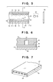
- FIGs. 5, 6, and 7 show an example of the structure of a head as the main part of the apparatus.
- a head 31 is obtained by bonding a glass, ceramic, or plastic plate having a groove 14, through which an ink flows, to a heating head 15 (although Fig. 5 shows the head, the present invention is not limited to this) used for thermal printing.
- the heating head 15 is constituted by a protective film 16 made of silicon oxide or the like, aluminum electrodes 17-1 and 17-2, a heating resistive layer 18 made of nichrome or the like, a heat accumulating layer 19, and a substrate 20 made of alumina or the like and having good heat dissipation properties.
- An ink 21 reaches a discharge orifice (pore) 22, and forms a meniscus 23 with a pressure P.
- FIG. 7 shows the outer appearance of a multi-head having a large number of heads, each identical to the one shown in Fig. 5. This multi-head is manufactured by bonding a glass plate 27 having multi-grooves 26 to a heating head 28 similar to the one described with reference to Fig. 5.
- Fig. 6 is a sectional view of the head 31 taken along the ink path.
- Fig. 6 is a sectional view taken along a line 3 - 3' in Fig. 5.
- Fig. 8 shows an example of the ink-jet print apparatus incorporating such a head.
- reference numeral 61 denotes a blade as a wiping member.
- One end of the blade 61 is a fixed end held by a blade holding member in the form of a cantilever.
- the blade 61 is placed nearer to the print area than the print head. In this case, the blade 61 is held to protrude into the path of the print head.
- Reference numeral 62 denotes a cap, which is placed at a home position adjacent to the blade 61. The cap 62 moves in a direction perpendicular to the moving direction of the print head to come into contact with the discharging opening surface, thereby capping the surface.
- Reference numeral 63 denotes an ink absorber placed to be adjacent to the blade 61.
- the blade 61, the cap 62, and the ink absorber 63 constitute a discharge restoring unit 64 to remove the moisture and dust on the ink discharging opening surface by the blade 61 and the ink absorber 63.
- Reference numeral 65 denotes a print head having a discharging energy generating means and designed to perform a print operation by discharging an ink to a recording medium opposing a discharging opening surface having discharging openings; and 66, a carriage having the print head 65 mounted thereon and designed to move it.
- the carriage 66 is slidably engaged with a guide shaft 67. A portion of the carriage 66 is connected (not shown) to a belt 69 driven by a motor 68. With this structure, the carriage 66 can move along the guide shaft 67 to allow the print head 65 to move to a print area and its adjacent area.
- Reference numeral 51 denotes a paper feed unit; and 52, a feed roller.
- the cap 62 of the discharge restoring unit 64 is retracted from the path of the print head 65, but the blade 61 is protruding into the path. As a result, the discharging opening surface of the print head 65 is wiped. Note that when the cap 62 comes into contact with the protruding surface of the print head 65 to cap it, the cap 62 moves to protrude into the path of the print head 65.
- the cap 62 and the blade 61 are at the same positions as those in the above wiping operation. As a result, the discharging opening surface of the print head 65 is wiped in the process of this movement.
- the print head moves to the home position at the end of the print operation and in the discharge restoring operation.
- the print head moves to the home position adjacent to a print area at predetermined intervals while the print head moves in the print area to perform a print operation. In the process of this movement, the above wiping operation is performed.
- print heads respectively containing black, cyan, magenta, and yellow inks are arranged side by side on the carriage 66.
- the four print heads may be arranged in a vertical array instead of being arranged side by side.
- inks of three colors i.e., cyan, magenta, and yellow, may be used instead of inks of the four colors.
- multiple printing may be performed for one dot by using inks having high and low densities. If the amount of ink landed increases, a drying mechanism such as a blower or heater may be used.
- the image preservation determination unit incorporates an optical density/color difference detector constituted by a light-emitting element such as a halogen lamp or LED, a light-receiving element such as a CCD or spectral sensor, and a microcomputer.
- a storage unit such as a hard disk is preferably connected to the microcomputer to store data. If data such as the initial OD, print date, patient name, and the like of each medical image are stored in the storage unit, and other medical data can be searched out. In addition, the stored data can be searched out from other terminals. Data such as an ID number may be printed on a peripheral portion such as a portion near the image preservation determination portion of a film in the form of a bar code.
- the size of the image preservation determination area of a print needs to be about 3 x 3 mm for each density in consideration of positioning and measurement stability. Since an excessively large size will interfere with diagnosis, the size is preferably set to be 25 x 25 mm or less. Alternatively, a gray scale exhibiting a continuous change in density may be printed. In this case, the density data is stored as a profile which continuously changes.
- the corresponding digital data is output after divided into signals in units of densities.
- a gray scale is also output with an image print ink, together with a gray scale for image preservation determination
- the presence/absence of the gradation difference between the original image and the output image can be determined by measuring the gray scale and comparing it with the original data in the image preservation determination unit. If a problem is posed in terms of gradation, an alarming means such as a buzzer or lamp is operated. If no problem is posed, the image is discharged.
- the read gradation data is stored in the storage unit, together with the ID number.
- Fig. 1 is a block diagram showing an apparatus according to the first embodiment of the present invention.
- a program for managing recording films in accordance with the flow chart of Fig. 2 is installed in the microcomputer of this apparatus. Medical images are stored as digital signals in a hard disk 1.
- the microcomputer Upon reception of an image retrieval instruction from a keyboard 2, the microcomputer checks the past image output history (step S1). If the image was output in the past (YES in step S1), the film is retrieved from a stocker 3 (step S3). If the image was not output in the past (NO in step S1), a new recording film is retrieved, and the image is output (step S9). In this case, since the image was not output in the past, it is output as a new image, and the image output history count is set as one. The image is output by a printer 4.
- the printer 4 contains two types of inks, which were respectively prepared as follows.
- One type of ink was a medical image print ink using CI.
- Direct Black 19 as a coloring material.
- the concentrations of the coloring materials were set to 4.0, 3.0, 1.5, and 0.7 wt%.
- As humectants 3.0 wt% of glycerine, 3.0 wt% of ethylene glycol, and 3.0 wt% of urea were added to the coloring material, and the balance was ion exchange water; the total amount was 100 wt%.
- the other type of ink is an image preservation determination ink, which was prepared by using CI.
- Direct Black 168 as a coloring material.
- the concentration of the coloring material was 3.0 wt%.
- An X-ray photograph was printed on the image print portion of color BJ transparency CF-301 (tradename; available from CANON INC.) as a recording film, together with five types of 5 x 5-mm black solids for image preservation determination, which were printed on a border portion of the film, with these inks by using a bubble-jet printer head (40 x 40 ⁇ m (orifice diameter) x 64 (nozzles) x 5 (chips)).
- the measured optical densities of these black solids were 0.49, 1.03, 1.49, 2.02, and 2.51, respectively.
- the ID number is also printed as a bar code on the border portion (step S10). These data are stored in the hard disk in the microcomputer (step S11).
- a film 5 having undergone a series of operations is discharged from a discharge port 6 (step S6).
- the measured optical densities of X-ray photograph portions at five points were 0.52, 1.03, 1.55, 2.22, and 2.85, respectively.
- step S8 When an instruction to output this image is input through the keyboard 2 again, since the image output history count is 1, the stocker 3 is searched to take out the film 5 therefrom (step S8).
- the optical densities of the black solids on the image preservation determination portion of the film 5 are automatically measured (step S4). In this case, the measurement values were 0.43, 0.87, 1.34, 1.83, and 2.31, respectively.
- step S5 When the data were compared with the data in the microcomputer (step S5), the density of some portion changed by 10% or more.
- An alarm lamp 7 was turned on to warn about the possibility of deterioration (YES in step S7). If the density of some portion has changed by 20% or more, since the possibility of deterioration is high, a warning message is also displayed on a display 8 in a noticeable form (step S12).
- step S8 whether to output the old film or a new film is selected.
- the old film 5 was taken out to check the degree of deterioration.
- the measured optical densities of the X-ray photograph portions at the five points were 0.49, 0.98, 1.49, 2.16, and 2.80, respectively.
- the average optical density decreased by about 3% compared with those before the film was left alone; a slight deterioration had occurred.
- An image preservation determination ink was prepared as a coloring material by using CI. Food Black 2.
- the concentration of the coloring material was 4.0 wt%.
- organic solvents 3.0 wt% of glycerine, 3.0 wt% of ethylene glycol, and 3.0 wt% of urea were added to the coloring material, and the balance was ion exchange water; the total amount was 100 wt%.
- Solids were printed by using this image preservation determination ink in the same manner as in the first embodiment except that OHP sheet MJOHPSI (tradename) for Mach Jet Color available from EPSON was used.
- OHP sheet MJOHPSI tradename for Mach Jet Color available from EPSON was used.
- This recording sheet was left alone in a room at a position where it was exposed to sunlight through a windowpane for one week, and was then returned into the apparatus.
- the alarm lamp 7 was turned on.
- the recording sheet was taken out, and the optical densities of medical image portions were measured, the average optical density was lower than that of the sheet before it was left alone in the room by about 4%.
- Aluminum dodexide was manufactured by the method disclosed in U.S.P. No. 4,242,271.
- Aluminum alkotoside was hydrolyzed to manufacture an alumina slurry by the method disclosed in U.S. Patent No. 4,202,870.
- Water was added to this alumina slurry until an alumina hydrate having a boehmite structure became 7.3%.
- the pH of the alumina slurry was 9.1.
- the pH was adjusted by a 3.9% nitrate solution adding to the slurry.
- a colloidal sol was obtained under the following aging conditions: aging temperature: 147°C; aging period: seven hours; and aging apparatus: autoclave.
- An alumina hydrate power having a boehmite structure was formed by performing spray drying with respect to this colloidal sol at 87°C.
- an alumina dispersion solution was formed by mixing 17 wt% of the alumina hydrate having the above boehmite structure into ion exchange water.
- a PVA solution was formed by mixing 20 wt% of polyvinyl alcohol (Gosenole NH18 to be referred to as PVA hereinafter available from Nihongoseikagaku kogyo K.K) into ion exchange water.
- the alumina dispersion solution and the PVA solution were mixed at 18 : 1 to form a coating solution.
- This coating solution was applied onto a polyethylene terephthalate film having a thickness of 188 ⁇ m by using an extrusion coater. This solution was then dried. At this time, the coating weight of the ink-receiving layer was 40 g/cm 2 .
- the recording medium formed in this manner was cut into a half size and used for a print operation.
- a coloring material for an image print ink a material, obtained by mixing carbon black and CI. Food Black 2 at a ratio of 1 : 1 was used.
- the print method of the present invention in the ink-jet print method of printing a medical image, pieces of information for image preservation determination are printed in a predetermined place other than the effective area of an image, and the corresponding data is stored in the storage unit in the apparatus.
- this data is compared with the corresponding initial value to detect slight changes that are difficult to discriminate with the naked eye, e.g., color deterioration, color change, and the like of the dye, can be detected.
- a warning can be generated. Erroneous use of such an image for diagnosis can therefore be prevented.
- the image can be reused as a reference image, thereby allowing the effective use of the resources.
- a gray scale is used as information for image preservation determination, data before deterioration can be reproduced on the basis of the initial value of the gray scale. Assume that original image data is destroyed. Even in this case, if only the initial value of the gray scale is stored, the original image can be reproduced by reading the image printed on a film with a scanner, performing density correction upon comparison between the current read value from the gray scale with the initial value, and outputting the resultant image from the printer.
- the preservation of an image improves. Even if, the image deteriorates or the original data is lost for some unexpected reason, the image can be reproduced, and the storage safety improves.
- This embodiment is applied to the print apparatus of the system, among various ink-jet print systems, which has a means (e.g., an electrothermal converter or laser light) for generating heat energy as energy used to discharge an ink, and changes the state of an ink by using the heat energy.
- a means e.g., an electrothermal converter or laser light
- a satisfactory effect can be obtained when the on-demand type apparatus is employed because of the structure arranged in such a manner that one or more drive signals, which rapidly raise the temperature of an electrothermal converter disposed to face a sheet or a fluid passage which holds the fluid (ink) to a level higher than levels at which film boiling takes place are applied to the electrothermal converter in accordance with print information so as to generate heat energy in the electrothermal converter and to cause the heat effecting surface of the print head to take place film boiling so that bubbles can be formed in the fluid (ink) to correspond to the one or more drive signals.
- the enlargement/contraction of the bubble will cause the fluid (ink) to be discharged through a discharging opening so that one or more ink dots are formed.
- a pulse shape drive signal is employed, the bubble can be enlarged/contracted immediately and properly, causing a further preferred effect to be obtained because the fluid (ink) can be discharged while revealing excellent responsibility.
- a structure having an arrangement that the heat effecting surface is disposed in a bent region and disclosed in U.S. Patent No. 4,558,333 or 4,459,600 may be employed.
- the following structures may be employed: a structure having an arrangement that a common slit is formed to serve as a discharge section of a plurality of electrothermal converters and disclosed in Japanese Patent Laid-Open No. 59-123670; and a structure disclosed in Japanese Patent Laid-Open No. 59-138461 in which an opening for absorbing pressure waves of heat energy is disposed to correspond to the discharge section.
- a print head of the full line type having a length corresponding to the maximum width of a recording medium which can be printed by the print apparatus
- either the construction which satisfies its length by a combination of a plurality of print heads as disclosed in the above specifications or the construction as a single full line type print head which has integrally been formed can be used.
- the invention is effective for a print head of the freely exchangeable chip type which enables electrical connection to the print apparatus main body or supply of ink from the main device by being mounted onto the apparatus main body, or for the case by use of a print head of the cartridge type provided integrally on the print head itself.
- the print head restoring means and the auxiliary means provided as the component of the present invention because the effect of the present invention can be further stabled.
- a print head capping means a cleaning means, a pressurizing or suction means, an electrothermal converter, another heating element or a preheating means constituted by combining them and a pre-discharging mode in which a discharging operation is performed independently from the print operation in order to stably perform the print operation.
- the print apparatus may have at least one of a multi-color mode using different colors and a full-color mode using color mixtures, as well as a print mode using only a main color such as black, with an integral print head or a combination of print heads.
- this embodiment is based on the assumption that a liquid ink is employed, an ink which solidifies at the room temperature or lower, or an ink which softens or liquifies at the room temperature may be used.
- temperature control is generally performed such that the temperature of an ink itself is adjusted within the range of 30°C to 70°C to set the viscosity of the ink within a stable discharge range. That is, any ink which liquifies when a print signal is supplied may be used.
- an ink which is solidified when it is caused to stand, and liquified when heat energy is supplied in accordance with a print signal can be adapted to the present invention to positively prevent a temperature rise caused by heat energy by utilizing the temperature rise as energy of state transition from the solid state to the liquid state or to prevent ink evaporation.
- an ink which is liquified when heat energy is supplied in accordance with a print signal so as to be discharged in the form of fluid ink, or an ink which is liquified only after heat energy is supplied, e.g., an ink which starts to solidify when it reaches a recording medium, can be adapted to the present invention.
- the ink may be of a type which is held as fluid or solid material in a recess of a porous sheet or a through hole at a position to face the electrothermal converter as disclosed in Japanese Patent Laid-Open No. 54-56847 or Japanese Patent Laid-Open No. 60-71260. It is the most preferred way for the ink to be adapted to the above film boiling method.
- the print apparatus of the present invention may take the form of an image output terminal integrally or separately provided for information processing equipment such as a computer, a copying machine combined with a reader or the like, or a facsimile apparatus having a transmission/reception function.
- information processing equipment such as a computer, a copying machine combined with a reader or the like, or a facsimile apparatus having a transmission/reception function.
Landscapes
- Ink Jet Recording Methods And Recording Media Thereof (AREA)
- Ink Jet (AREA)
Claims (10)
- Tintenstrahl-Druckverfahren zum Druck eines Bildes auf ein Aufzeichnungsmedium durch Austrag von Tinte aus einem Druckkopf, dadurch gekennzeichnet, dass es den Druck eines Sub-Bildes zur Bestimmung des Bild-Erhaltungszustandes an einer außerhalb des effektiven Bildbereiches liegenden Stelle einschließt (S9, S10).
- Verfahren nach Anspruch 1,
wobei das Sub-Bild unter Nutzung einer Tinte zur Bestimmung des Bild-Erhaltungszustandes, welche einen organischen Farbstoff als Färbematerial enthält, gedruckt wird. - Verfahren nach Anspruch 1 oder 2,
wobei das Aufzeichnungsmedium auf einer Oberfläche einer porösen Tintenaufnahmeschicht und ein optisches Transmissionsvermögen von nicht weniger als 50 % hat. - Verfahren nach Anspruch 3,
wobei die poröse Tintenaufnahmeschicht mindestens Tonerde oder Kieselerde enthält. - Verfahren nach Anspruch 3 oder 4,
wobei die poröse Tintenaufnahmeschicht ein Pseudo-Boehmit enthält. - Tintenstrahl-Druckvorrichtung zum Druck eines Bildes auf ein Aufzeichnungsmedium durch Austrag einer Tinte aus einem Tintenkopf, gekennzeichnet durch eine Druckeinrichtung zum Drucken eines Sub-Bildes zur Bestimmung eines Bild-Erhaltungszustandes an einer vorbestimmten Stelle außerhalb eines effektiven Bildbereiches, wobei die Druckeinrichtung das Sub-Bild unter Verwendung einer Tinte zur Bestimmung des Bild-Erhaltungszustandes druckt.
- Tintenstrahlaufzeichnungsmedium, auf welches ein Bild mit einer aus einem Druckkopf ausgetragenen Tinte gedruckt wird,
wobei ein Bild zur Bestimmung des Informations-Erhaltungszustandes auf eine Stelle außerhalb des effektiven Bildbereiches unter Einsatz einer Tinte zur Bestimmung des Bild-Erhaltungszustandes gedruckt wird. - Tintenstrahl-Druckvorrichtung zum Druck eines Bildes auf ein Aufzeichnungsmedium durch Austrag von Tinte aus einem Druckkopf, gekennzeichnet durch eine Druckeinrichtung zum Druck eines Sub-Bildes zur Bestimmung des Bild-Erhaltungszustandes an eine Stelle außerhalb eines effektiven Bildbereiches und
eine Einrichtung zur Bestimmung des Bild-Erhaltungszustandes, die eine Erfassungseinheit zur Bestimmung des Erhaltungszustandes des Bildes hat, welche durch mindestens ein lichtemittierendes Element und ein lichtempfangendes Element gebildet ist,
wobei die Einrichtung zur Bestimmung des Bild-Erhaltungszustandes den Erhaltungszustand des Bildes auf der Basis einer optischen Dichte oder einer Farbabweichung des mit der Tinte zur Bestimmung des Bild-Erhaltungszustandes gedruckten Sub-Bildes ermittelt. - Verfahren zur Bestimmung eines Bild-Erhaltungszustandes, gekennzeichnet durch die Schritte:Druck eines Bildes auf einer Bilddruckfläche auf einem Aufzeichnungsmedium unter Einsatz eines ersten Druckmaterials (S9),Drucken von Information in einem Gebiet zur Bestimmung des Bild-Erhaltungszustandes in einem Grenzbereich als Gebiet außerhalb der Bilddruckfläche unter Einsatz eines zweiten Druckmaterials, welches schneller degeneriert als das erste Druckmaterial (S10), undoptische Erfassung der Fläche zur Bestimmung des Bild-Erhaltungszustandes und Bestimmung dessen, ob das Bild sich verschlechtert hat (S4, S5).
- Druckvorrichtung zum Drucken eines Bildes auf ein Aufzeichnungsmedium, gekennzeichnet durch:eine erste Druckeinrichtung zum Drucken eines Bildes auf eine Bilddruckfläche auf dem Aufzeichnungsmedium,eine zweite Druckeinrichtung zum Drucken eines Sub-Bildes auf einer Fläche zur Bestimmung des Bild-Erhaltungszustandes außerhalb der Bilddruckfläche durch Austragen einer Tinte aus einem Druckkopf.
Applications Claiming Priority (3)
| Application Number | Priority Date | Filing Date | Title |
|---|---|---|---|
| JP321720/96 | 1996-12-02 | ||
| JP32172096A JP3363720B2 (ja) | 1996-12-02 | 1996-12-02 | インクジェット記録方法、かかる方法に用いるインクジェット記録装置およびかかる方法で記録したインクジェット記録物 |
| JP32172096 | 1996-12-02 |
Publications (3)
| Publication Number | Publication Date |
|---|---|
| EP0845366A2 EP0845366A2 (de) | 1998-06-03 |
| EP0845366A3 EP0845366A3 (de) | 1999-05-06 |
| EP0845366B1 true EP0845366B1 (de) | 2003-04-09 |
Family
ID=18135696
Family Applications (1)
| Application Number | Title | Priority Date | Filing Date |
|---|---|---|---|
| EP97121068A Expired - Lifetime EP0845366B1 (de) | 1996-12-02 | 1997-12-01 | Tintenstrahldruckverfahren, Tintenstrahldruckapparat für dieses Verfahren und durch dieses Verfahren hergestelltes Druckerzeugnis |
Country Status (4)
| Country | Link |
|---|---|
| US (1) | US6457799B1 (de) |
| EP (1) | EP0845366B1 (de) |
| JP (1) | JP3363720B2 (de) |
| DE (1) | DE69720658T2 (de) |
Families Citing this family (3)
| Publication number | Priority date | Publication date | Assignee | Title |
|---|---|---|---|---|
| JP2003072186A (ja) * | 2001-06-19 | 2003-03-12 | Canon Inc | 画像形成装置及び画像形成方法及びプログラム並びに記録媒体 |
| US20040001692A1 (en) * | 2002-06-28 | 2004-01-01 | Fuji Photo Film Co., Ltd. | Image recording method, image recording apparatus, and image recording medium |
| US20090103118A1 (en) * | 2007-10-22 | 2009-04-23 | Kabushiki Kaisha Toshiba | Color conversion apparatus |
Family Cites Families (28)
| Publication number | Priority date | Publication date | Assignee | Title |
|---|---|---|---|---|
| CA1127227A (en) | 1977-10-03 | 1982-07-06 | Ichiro Endo | Liquid jet recording process and apparatus therefor |
| JPS5459936A (en) | 1977-10-03 | 1979-05-15 | Canon Inc | Recording method and device therefor |
| JPS5936879B2 (ja) | 1977-10-14 | 1984-09-06 | キヤノン株式会社 | 熱転写記録用媒体 |
| US4330787A (en) | 1978-10-31 | 1982-05-18 | Canon Kabushiki Kaisha | Liquid jet recording device |
| US4345262A (en) | 1979-02-19 | 1982-08-17 | Canon Kabushiki Kaisha | Ink jet recording method |
| US4463359A (en) | 1979-04-02 | 1984-07-31 | Canon Kabushiki Kaisha | Droplet generating method and apparatus thereof |
| US4242271A (en) | 1979-04-23 | 1980-12-30 | Union Carbide Corporation | Process for preparing aluminum alkoxides |
| US4202870A (en) | 1979-04-23 | 1980-05-13 | Union Carbide Corporation | Process for producing alumina |
| US4313124A (en) | 1979-05-18 | 1982-01-26 | Canon Kabushiki Kaisha | Liquid jet recording process and liquid jet recording head |
| US4558333A (en) | 1981-07-09 | 1985-12-10 | Canon Kabushiki Kaisha | Liquid jet recording head |
| JPS59123670A (ja) | 1982-12-28 | 1984-07-17 | Canon Inc | インクジエツトヘツド |
| JPS59138461A (ja) | 1983-01-28 | 1984-08-08 | Canon Inc | 液体噴射記録装置 |
| JPS6071260A (ja) | 1983-09-28 | 1985-04-23 | Erumu:Kk | 記録装置 |
| JPH0811452B2 (ja) * | 1986-10-27 | 1996-02-07 | ミノルタ株式会社 | レーザプリンタ |
| US4757334A (en) * | 1986-12-09 | 1988-07-12 | Ivan Volent | System for density correction of medical imaging film hard copy |
| DE3807121A1 (de) * | 1988-03-04 | 1989-09-14 | Siemens Ag | Elektrofotografische druckeinrichtung mit geregeltem elektrofotografischen prozess |
| JP3049663B2 (ja) * | 1991-02-20 | 2000-06-05 | キヤノン株式会社 | 記録装置及び記録方法 |
| JPH0511549A (ja) * | 1991-07-02 | 1993-01-22 | Hitachi Ltd | 電子写真装置 |
| US5451990A (en) * | 1993-04-30 | 1995-09-19 | Hewlett-Packard Company | Reference pattern for use in aligning multiple inkjet cartridges |
| JPH07125255A (ja) * | 1993-09-13 | 1995-05-16 | Canon Inc | 画像記録装置及びその方法及びファクシミリ装置 |
| US5689289A (en) * | 1993-11-30 | 1997-11-18 | Canon Kabushiki Kaisha | Image recording apparatus |
| JPH09500514A (ja) * | 1994-05-06 | 1997-01-14 | フィリップス エレクトロニクス エヌ ベー | ハードコピーユニットの調整方法及び装置 |
| JPH07323573A (ja) | 1994-06-01 | 1995-12-12 | Murata Mach Ltd | 印字装置 |
| JP3398475B2 (ja) | 1994-06-20 | 2003-04-21 | 旭硝子株式会社 | インクジェット記録シートの製造方法 |
| JPH08160693A (ja) * | 1994-12-07 | 1996-06-21 | Canon Inc | 画像形成装置 |
| JPH08183189A (ja) | 1994-12-28 | 1996-07-16 | Canon Inc | ファクシミリ装置および該装置による付帯情報の記録方法 |
| US5740428A (en) * | 1995-02-07 | 1998-04-14 | Merge Technologies, Inc. | Computer based multimedia medical database management system and user interface |
| JPH09169159A (ja) * | 1995-07-21 | 1997-06-30 | Canon Inc | 記録媒体、これを用いた画像形成方法及び印字物 |
-
1996
- 1996-12-02 JP JP32172096A patent/JP3363720B2/ja not_active Expired - Fee Related
-
1997
- 1997-12-01 EP EP97121068A patent/EP0845366B1/de not_active Expired - Lifetime
- 1997-12-01 DE DE69720658T patent/DE69720658T2/de not_active Expired - Fee Related
- 1997-12-02 US US08/982,520 patent/US6457799B1/en not_active Expired - Fee Related
Also Published As
| Publication number | Publication date |
|---|---|
| DE69720658D1 (de) | 2003-05-15 |
| DE69720658T2 (de) | 2003-10-16 |
| US6457799B1 (en) | 2002-10-01 |
| JPH10157088A (ja) | 1998-06-16 |
| EP0845366A3 (de) | 1999-05-06 |
| EP0845366A2 (de) | 1998-06-03 |
| JP3363720B2 (ja) | 2003-01-08 |
Similar Documents
| Publication | Publication Date | Title |
|---|---|---|
| EP0350257B1 (de) | Aufzeichnungsmaterial und Tintenstrahl-Aufzeichnungsverfahren unter Verwendung dieses Materials | |
| US4550053A (en) | Recording medium | |
| KR0173152B1 (ko) | 기록 매체 및 그를 이용한 화상 형성 방법 | |
| US4801497A (en) | Recording medium | |
| GB2184958A (en) | Ink jet recording medium | |
| US20090315963A1 (en) | Ink jet printing apparatus and method for determining drying condition for print image | |
| EP0754561B1 (de) | Aufzeichnungsmaterial, Bilderzeugungsverfahren und bedrucktes Produkt das dieses Material verwendet | |
| EP0845366B1 (de) | Tintenstrahldruckverfahren, Tintenstrahldruckapparat für dieses Verfahren und durch dieses Verfahren hergestelltes Druckerzeugnis | |
| EP1016543B1 (de) | Verfahren zur Herstellung eines Aufzeichnungsmediums | |
| EP1386751B1 (de) | Tintenstrahlaufzeichnungselement und Druckverfahren | |
| GB2175516A (en) | Recording medium | |
| JP2003335057A (ja) | オゾン耐性の向上したインクジェット記録シート | |
| EP1613483B1 (de) | Verfahren zur verbesserung der ozonstabilität der tintenfarbstoffe auf ein tintenstrahlaufzeichnungselements gedrukt | |
| JP2004082734A (ja) | インクジェット印刷方法 | |
| JP2000211239A (ja) | 近赤外吸収化合物を含有する被記録媒体および該媒体を用いた画像形成方法 | |
| JP3810104B2 (ja) | インクジェット用被記録材 | |
| EP1742804B1 (de) | Verfahren zur verbesserung der ozonstabilität eines tintenstrahlaufzeichnungselements | |
| JPH0669753B2 (ja) | インクジェット用被記録材 | |
| JP2694042B2 (ja) | 被記録材の製造方法 | |
| EP1310378B1 (de) | Tintenstrahlaufzeichnungsmedien und deren Herstellung | |
| JP2000103043A (ja) | インクジェット記録方法 | |
| JP3809671B2 (ja) | インクジェット記録用印画紙 | |
| EP1226965B1 (de) | Tintanstrahlaufzeichnungselement und Aufzeichnungsverfahren | |
| JPH09109544A (ja) | インクジェット用記録シート | |
| EP2637872B1 (de) | Transparente tintenstrahlaufzeichnungsfolien, zusammensetzungen und verfahren |
Legal Events
| Date | Code | Title | Description |
|---|---|---|---|
| PUAI | Public reference made under article 153(3) epc to a published international application that has entered the european phase |
Free format text: ORIGINAL CODE: 0009012 |
|
| AK | Designated contracting states |
Kind code of ref document: A2 Designated state(s): DE ES FR GB IT NL |
|
| AX | Request for extension of the european patent |
Free format text: AL;LT;LV;MK;RO;SI |
|
| PUAL | Search report despatched |
Free format text: ORIGINAL CODE: 0009013 |
|
| AK | Designated contracting states |
Kind code of ref document: A3 Designated state(s): AT BE CH DE DK ES FI FR GB GR IE IT LI LU MC NL PT SE |
|
| AX | Request for extension of the european patent |
Free format text: AL;LT;LV;MK;RO;SI |
|
| 17P | Request for examination filed |
Effective date: 19991105 |
|
| AKX | Designation fees paid |
Free format text: DE ES FR GB IT NL |
|
| 17Q | First examination report despatched |
Effective date: 20001219 |
|
| GRAG | Despatch of communication of intention to grant |
Free format text: ORIGINAL CODE: EPIDOS AGRA |
|
| GRAG | Despatch of communication of intention to grant |
Free format text: ORIGINAL CODE: EPIDOS AGRA |
|
| GRAH | Despatch of communication of intention to grant a patent |
Free format text: ORIGINAL CODE: EPIDOS IGRA |
|
| GRAH | Despatch of communication of intention to grant a patent |
Free format text: ORIGINAL CODE: EPIDOS IGRA |
|
| GRAA | (expected) grant |
Free format text: ORIGINAL CODE: 0009210 |
|
| AK | Designated contracting states |
Designated state(s): DE ES FR GB IT NL |
|
| PG25 | Lapsed in a contracting state [announced via postgrant information from national office to epo] |
Ref country code: IT Free format text: LAPSE BECAUSE OF FAILURE TO SUBMIT A TRANSLATION OF THE DESCRIPTION OR TO PAY THE FEE WITHIN THE PRE;WARNING: LAPSES OF ITALIAN PATENTS WITH EFFECTIVE DATE BEFORE 2007 MAY HAVE OCCURRED AT ANY TIME BEFORE 2007. THE CORRECT EFFECTIVE DATE MAY BE DIFFERENT FROM THE ONE RECORDED.SCRIBED TIME-LIMIT Effective date: 20030409 Ref country code: FR Free format text: LAPSE BECAUSE OF FAILURE TO SUBMIT A TRANSLATION OF THE DESCRIPTION OR TO PAY THE FEE WITHIN THE PRESCRIBED TIME-LIMIT Effective date: 20030409 |
|
| REG | Reference to a national code |
Ref country code: GB Ref legal event code: FG4D |
|
| REF | Corresponds to: |
Ref document number: 69720658 Country of ref document: DE Date of ref document: 20030515 Kind code of ref document: P |
|
| PG25 | Lapsed in a contracting state [announced via postgrant information from national office to epo] |
Ref country code: ES Free format text: LAPSE BECAUSE OF FAILURE TO SUBMIT A TRANSLATION OF THE DESCRIPTION OR TO PAY THE FEE WITHIN THE PRESCRIBED TIME-LIMIT Effective date: 20031030 |
|
| PLBE | No opposition filed within time limit |
Free format text: ORIGINAL CODE: 0009261 |
|
| STAA | Information on the status of an ep patent application or granted ep patent |
Free format text: STATUS: NO OPPOSITION FILED WITHIN TIME LIMIT |
|
| EN | Fr: translation not filed | ||
| 26N | No opposition filed |
Effective date: 20040112 |
|
| PGFP | Annual fee paid to national office [announced via postgrant information from national office to epo] |
Ref country code: NL Payment date: 20081219 Year of fee payment: 12 |
|
| PGFP | Annual fee paid to national office [announced via postgrant information from national office to epo] |
Ref country code: DE Payment date: 20081231 Year of fee payment: 12 |
|
| PGFP | Annual fee paid to national office [announced via postgrant information from national office to epo] |
Ref country code: GB Payment date: 20081224 Year of fee payment: 12 |
|
| REG | Reference to a national code |
Ref country code: NL Ref legal event code: V1 Effective date: 20100701 |
|
| GBPC | Gb: european patent ceased through non-payment of renewal fee |
Effective date: 20091201 |
|
| PG25 | Lapsed in a contracting state [announced via postgrant information from national office to epo] |
Ref country code: NL Free format text: LAPSE BECAUSE OF NON-PAYMENT OF DUE FEES Effective date: 20100701 |
|
| PG25 | Lapsed in a contracting state [announced via postgrant information from national office to epo] |
Ref country code: DE Free format text: LAPSE BECAUSE OF NON-PAYMENT OF DUE FEES Effective date: 20100701 |
|
| PG25 | Lapsed in a contracting state [announced via postgrant information from national office to epo] |
Ref country code: GB Free format text: LAPSE BECAUSE OF NON-PAYMENT OF DUE FEES Effective date: 20091201 |