EP0843390B1 - Universal manual crimping tool - Google Patents
Universal manual crimping tool Download PDFInfo
- Publication number
- EP0843390B1 EP0843390B1 EP97111216A EP97111216A EP0843390B1 EP 0843390 B1 EP0843390 B1 EP 0843390B1 EP 97111216 A EP97111216 A EP 97111216A EP 97111216 A EP97111216 A EP 97111216A EP 0843390 B1 EP0843390 B1 EP 0843390B1
- Authority
- EP
- European Patent Office
- Prior art keywords
- swage
- hand
- crimping
- receptacle
- pliers according
- Prior art date
- Legal status (The legal status is an assumption and is not a legal conclusion. Google has not performed a legal analysis and makes no representation as to the accuracy of the status listed.)
- Expired - Lifetime
Links
- 238000002788 crimping Methods 0.000 title claims description 33
- 229910000831 Steel Inorganic materials 0.000 claims description 5
- 239000010959 steel Substances 0.000 claims description 5
- 230000003068 static effect Effects 0.000 claims description 3
- 230000005540 biological transmission Effects 0.000 claims description 2
- 239000011324 bead Substances 0.000 description 36
- 238000003825 pressing Methods 0.000 description 7
- 238000004519 manufacturing process Methods 0.000 description 4
- 238000000034 method Methods 0.000 description 4
- 238000005452 bending Methods 0.000 description 3
- 239000002184 metal Substances 0.000 description 3
- 229910052751 metal Inorganic materials 0.000 description 3
- 238000007493 shaping process Methods 0.000 description 2
- 238000010276 construction Methods 0.000 description 1
- 238000005520 cutting process Methods 0.000 description 1
- 230000009977 dual effect Effects 0.000 description 1
- 238000004080 punching Methods 0.000 description 1
- 230000000284 resting effect Effects 0.000 description 1
Images


Classifications
-
- B—PERFORMING OPERATIONS; TRANSPORTING
- B26—HAND CUTTING TOOLS; CUTTING; SEVERING
- B26F—PERFORATING; PUNCHING; CUTTING-OUT; STAMPING-OUT; SEVERING BY MEANS OTHER THAN CUTTING
- B26F1/00—Perforating; Punching; Cutting-out; Stamping-out; Apparatus therefor
- B26F1/32—Hand-held perforating or punching apparatus, e.g. awls
- B26F1/36—Punching or perforating pliers
-
- B—PERFORMING OPERATIONS; TRANSPORTING
- B25—HAND TOOLS; PORTABLE POWER-DRIVEN TOOLS; MANIPULATORS
- B25B—TOOLS OR BENCH DEVICES NOT OTHERWISE PROVIDED FOR, FOR FASTENING, CONNECTING, DISENGAGING OR HOLDING
- B25B7/00—Pliers; Other hand-held gripping tools with jaws on pivoted limbs; Details applicable generally to pivoted-limb hand tools
- B25B7/02—Jaws
-
- B—PERFORMING OPERATIONS; TRANSPORTING
- B25—HAND TOOLS; PORTABLE POWER-DRIVEN TOOLS; MANIPULATORS
- B25B—TOOLS OR BENCH DEVICES NOT OTHERWISE PROVIDED FOR, FOR FASTENING, CONNECTING, DISENGAGING OR HOLDING
- B25B7/00—Pliers; Other hand-held gripping tools with jaws on pivoted limbs; Details applicable generally to pivoted-limb hand tools
- B25B7/12—Pliers; Other hand-held gripping tools with jaws on pivoted limbs; Details applicable generally to pivoted-limb hand tools involving special transmission means between the handles and the jaws, e.g. toggle levers, gears
-
- H—ELECTRICITY
- H01—ELECTRIC ELEMENTS
- H01R—ELECTRICALLY-CONDUCTIVE CONNECTIONS; STRUCTURAL ASSOCIATIONS OF A PLURALITY OF MUTUALLY-INSULATED ELECTRICAL CONNECTING ELEMENTS; COUPLING DEVICES; CURRENT COLLECTORS
- H01R43/00—Apparatus or processes specially adapted for manufacturing, assembling, maintaining, or repairing of line connectors or current collectors or for joining electric conductors
- H01R43/04—Apparatus or processes specially adapted for manufacturing, assembling, maintaining, or repairing of line connectors or current collectors or for joining electric conductors for forming connections by deformation, e.g. crimping tool
- H01R43/042—Hand tools for crimping
- H01R43/0421—Hand tools for crimping combined with other functions, e.g. cutting
-
- B—PERFORMING OPERATIONS; TRANSPORTING
- B26—HAND CUTTING TOOLS; CUTTING; SEVERING
- B26F—PERFORATING; PUNCHING; CUTTING-OUT; STAMPING-OUT; SEVERING BY MEANS OTHER THAN CUTTING
- B26F1/00—Perforating; Punching; Cutting-out; Stamping-out; Apparatus therefor
- B26F1/32—Hand-held perforating or punching apparatus, e.g. awls
- B26F1/36—Punching or perforating pliers
- B26F2001/365—Punching or perforating pliers hand held pliers with handles
Definitions
- the invention relates to a universally applicable hand crimping pliers, which are characterized by Interchangeability of different dies and pressing tools for versatile cold forming of sheet metal and U profiles, in particular ceiling and wall profiles or for example, also suitable for crimping.
- punch pliers are used to punch openings, especially in plastic cans (OS DE 195 05 613), known or a beading device for the production of beaded electrical Connections according to AS 1144804.
- plastic cans OS DE 195 05 613
- beading device for the production of beaded electrical Connections according to AS 1144804.
- AS 1144804 it is not with any of the known devices possible to insert appropriate beads in sheet metal U-profiles or the special beading device can also be used for other cold forming operations
- a shaping tool according to PCT document WO-A-84/04475 (closest prior art) is also known, which is suitable for work such as bending and cutting, and from drive parts that are movable and are attached centrally to a tool body.
- drive parts that are movable and are attached centrally to a tool body.
- additional parts that are Have each inserted into the butt and support block provided with the tool part the possible uses of the bending tool are considerably increased, however no thin-walled C and U profiles can be machined with this tool either do not produce double beads.
- the invention has therefore set itself the task of one for a wide variety of operations to develop the cold forming universally applicable hand beads / crimping pliers with the thin-walled Sheet metal and U profiles, e.g. appropriately prepared ceilings CD or U profiles, as they are common in drywall construction, to be able to work on the spot, that with it a vertical or horizontal bending and thus manufacture of any desired Radius is possible and which is also suitable for other operations suitable, for example for crimping.
- the object is achieved in that a basic element as a static part, for example made of U-shaped steel sheet, and angled on its front and is tapered so that the resulting parallel outer sides of a fastening and the guide part was created.
- a basic element as a static part, for example made of U-shaped steel sheet, and angled on its front and is tapered so that the resulting parallel outer sides of a fastening and the guide part was created.
- the fastening and guide part is one right-angled and L-shaped die receptacle with a face firmly attached to it Screw bolt as a holder for a die lock for mounting with a locking pin provided dies.
- a sliding mount in which a flat steel, for example shaft connected with a notched bead wedge is accommodated.
- the bottom serves here of the L-shaped part of the die holder and a bolt that simultaneously also used as a stop for a lever with a grip element, as a guide.
- the front one for power transmission also U-shaped lever is designed so that between a hinge point in the base element and a connecting hinge pin as a fulcrum A lever arm is created, the force of which is via a double-sided connecting rod with a stud as a hinge point, on the shaft and thus, for example, on the notched bead wedge is transmitted.
- the die lock is preferably with one or more locking holes provided and preferably on the part pierced for the bolt, to improve the locking process into the locking holes of the dies pushed onto the die holder, slightly cranked.
- a spiral spring picked up by the bolt, which is located between the die lock and the upper edge of the base element is also facilitated the locking process.
- the notched bead wedge is preferably either fixed or detachably connected to the shaft, so that at any time depending on the conditions of use, an interchangeability either of the notched bead wedge or at permanent connections of the entire shaft-pressing tool unit, is possible.
- the dies that can be pushed onto the die holder via passage guides, for example Double-function dies are preferably slidable onto the die holder in such a way that the respective one Die cutout corresponds to the opposite notched bead wedge. That is, through the Appropriate application and combination of the respective dies are the most varied Beads, such as edge and bottom beads for the production of wall and ceiling profiles, can be inserted.
- a double-function die provided with locking pins preferably has one on one side Die cutout and on the opposite side a notched bead wedge so that it in the respective pressing process either only as a locking device arranged in front of it Double-function die or serves with the die holder or your own Notched bead wedge itself can be used as a shaping tool.
- One on the die holder if necessary slidably arranged double-function die is preferably on both sides with die mounts Mistake. However, one side has an additional recess, so that the die recess this side is open at the top and so there is free space for the profile to be processed or for combination with other double function dies.
- the shaft is provided with a crimp head instead of a notched bead wedge and finds it a working part slid onto the die holder and extended with an L-shape locked crimping die use
- the hand crimping pliers are also used as crimping pliers changeable.
- the hand beads / crimping pliers consist of a static part, as a basic element 1.
- the basic element 1 made of U-shaped steel sheet and open at the top is so angled in the front part and tapers so that through the resulting outer sides 2 a fastening and guiding part 3 is created.
- the upper part of the attachment and guide part 3 is used to attach a rectangular die holder 4 with an L-shaped screw part, and the lower part of the fastening and guide part 3 as a sliding mount for an existing flat steel, with a Notch bead wedge 5 firmly connected shaft 6.
- the U-shaped lever 16 is slightly cranked towards the handle side and its front is designed so that between the bearings on both sides in the base element 1 and with washers screwed hinge point 17 and a connecting hinge pin 18 as a fulcrum, a lever arm arises, the forces of which are via a double-sided connecting rod 19 via a Stud 20 is transferred to the shaft 6 and thus to the notched bead wedge 5.
- the Connecting rod 19 resting on both sides of the shaft 6 is by using the stud screw 20 exchangeable at any time.
- a bolt 21, which is also located in the base element 1, serves on the one hand the lever 16 as Stop and on the other hand, as the L-shaped screw part of the die holder 4, as Guide element for the shaft 6.
- the necessary stability in the front working area of the hand crimping tool results from Screwing the outer sides 2 together with the L-shaped screw part inserted therein the die holder 4 by means of connecting screws 22.
- a dual function die 12 for U-profiles and edge beads take over with its flat side over the in the locking hole 8 locked locking pin 11 the locking.
- the slidable double-function die 23 is pushed on that the smooth side with the die recess 25 is opposite the notched bead wedge 5 and the other offset recess 25 with the recess 26 opposite the notch bead 28 of the double-function die, which has also been postponed and locked 12, is arranged.
- the double-function die 12 with its flat side and the die recess 29 opposite the notched bead wedge 5 for deforming commercially available U-wall profiles 30 fixed in the front locking hole 8 of the die lock 9.
- 6 shows a further possibility for universal use of the beads / crimping pliers, in which, instead of the double-function dies, a crimp die 13 on the die holder 4 pushed on and locked via a locking hole 8 of the die lock 9 becomes.
- the shaft 6 was replaced with notched bead wedge 5 and by one Shank 6 replaced with crimping head 31 as a stamped part.
- the crimping die 13 is designed so that the working part 32 is advanced so far that there is enough space for the work to be done Workpiece is available.
Landscapes
- Engineering & Computer Science (AREA)
- Mechanical Engineering (AREA)
- Manufacturing & Machinery (AREA)
- Life Sciences & Earth Sciences (AREA)
- Forests & Forestry (AREA)
- Gripping Jigs, Holding Jigs, And Positioning Jigs (AREA)
- Hand Tools For Fitting Together And Separating, Or Other Hand Tools (AREA)
- Connection Of Plates (AREA)
- Clamps And Clips (AREA)
Description
Die Erfindung betrifft eine universell verwendbare Handsicken/crimpzange, welche sich durch die Auswechselbarkeit der verschiedensten Gesenke und Drückwerkzeuge zur vielseitigen Kaltverformung von Blech- und U-Profilen, insbesondere von Decken- und Wandprofilen oder beispielsweise auch zum Crimpen, eignet.The invention relates to a universally applicable hand crimping pliers, which are characterized by Interchangeability of different dies and pressing tools for versatile cold forming of sheet metal and U profiles, in particular ceiling and wall profiles or for example, also suitable for crimping.
Es sind eine Vielzahl von Sickengeräten und Sickenzangen bekannt, um die verschiedensten, für spezielle Anwendungen gedachten, Quetschverbindungen, Stanzungen von Öffnungen etc. zu erreichen.A large number of beading devices and beading pliers are known in order to Intended for special applications, crimp connections, punching openings etc. to reach.
So sind zum Beispiel Stanzzangen zum Stanzen von Öffnungen, insbesondere in Kunststoffdosen (OS DE 195 05 613), bekannt oder ein Sickengerät zur Herstellung von gesickten elektrischen Verbindungen nach der AS 1144804. Mit keinem der bekannten Geräte ist es jedoch möglich, in Blech-U-Profilen entsprechende Sicken einzubringen oder das spezielle Sickengerät noch für andere Arbeitsgänge zur Kaltverformung einzusetzenFor example, punch pliers are used to punch openings, especially in plastic cans (OS DE 195 05 613), known or a beading device for the production of beaded electrical Connections according to AS 1144804. However, it is not with any of the known devices possible to insert appropriate beads in sheet metal U-profiles or the special beading device can also be used for other cold forming operations
Ferner ist ein Formungswerkzeug nach dem PCT-Dokument WO-A-84/04475 (nächstliegender Stand der Technik) bekannt, welches sich für Arbeiten, wie Biegen und Schneiden eignet, und aus Antriebsteilen, die beweglich und zentral auf einem Werkzeugkörper befestigt sind, besteht. Durch Zusatzteile, die sich jeweils in den mit dem Werkzeugteil vorhandenen Stoß- und Stützblock einbringen lassen sind die Gebrauchsmöglichkeiten des Biegewerkzeuges zwar beträchtlich vergrößert, jedoch lassen sich auch mit diesem Werkzeug keine dünnwandigen C- und U-Profile bearbeiten und keine Doppelsicken herstellen.A shaping tool according to PCT document WO-A-84/04475 (closest prior art) is also known, which is suitable for work such as bending and cutting, and from drive parts that are movable and are attached centrally to a tool body. Through additional parts that are Have each inserted into the butt and support block provided with the tool part the possible uses of the bending tool are considerably increased, however no thin-walled C and U profiles can be machined with this tool either do not produce double beads.
Die Erfindung hat sich daher die Aufgabe gestellt, eine für die verschiedensten Arbeitsgänge der Kaltverformung universell anwendbare Handsicken/crimpzange zu entwickeln, mit der dünnwandige Blech- und U-Profile, zum Beispiel entsprechend vorbereitete Decken CD- oder U-Profile, wie sie im Trockenbau üblich sind, gleich an Ort und Stelle so bearbeiten zu können, daß damit ein vertikales oder horizontales Verbiegen und somit Herstellen eines jeden gewünschten Radius möglich ist und welche sich darüber hinaus noch für andere Arbeitsgänge eignet, beispielsweise zum Crimpen.The invention has therefore set itself the task of one for a wide variety of operations to develop the cold forming universally applicable hand beads / crimping pliers with the thin-walled Sheet metal and U profiles, e.g. appropriately prepared ceilings CD or U profiles, as they are common in drywall construction, to be able to work on the spot, that with it a vertical or horizontal bending and thus manufacture of any desired Radius is possible and which is also suitable for other operations suitable, for example for crimping.
Erfindungsgemäß wird die Aufgabe dadurch gelöst, daß ein Grundelement als statischer Teil, beispielsweise aus U-förmigen Stahlblech besteht, und an seiner Vorderseite so abgewinkelt und verjüngt ist, daß durch die sich so ergebenden parallelen Außenseiten ein Befestigungs- und Führungsteil entstanden ist. Im oberen Teil des Befestigungs- und Führungsteiles ist eine rechtwinklige und L-förmige Gesenkaufnahme mit einem stirnseitig daran fest verbundenen Schraubbolzen als Halterung für eine Gesenkarretierung zur Aufnahme mit einem Arretierungsstift versehener Gesenke eingebracht. Im unteren Teil des Befestigungs- und Führungsteiles befindet sich eine Gleitaufnahme, in der ein aus Flachstahl bestehender, beispielsweise mit einem Kerbsickenkeil verbundenen Schaft Aufnahme findet. Dabei dient die Unterseite des L-förmig ausgebildeten Teiles der Gesenkaufnahme sowie ein Bolzen, der gleichzeitig auch als Anschlag für einen Hebel mit Griffelement genutzt wird, als Führung. Die Vorderseite eines zur Kraftübertragung gleichfalls U-förmigen Hebels ist so gestaltet, daß zwischen einem im Grundelement gelagerten Gelenkpunkt und einem Verbindungsgelenkstift als Drehpunkt ein Hebelarm entsteht, dessen Kraft über eine doppelseitige Pleuelstange mit einer Stiftschraube als Gelenkpunkt, auf den Schaft und damit beispielsweise auf den Kerbsickenkeil übertragen wird. Die Gesenkarretierung ist vorzugsweise mit einer oder mehreren Arretierungsbohrungen versehen und vorzugsweise an dem für den Schraubbolzen durchbohrten Teil, zur Verbesserung des Einrastvorganges in die Arretierungsbohrungen der auf die Gesenkaufnahme aufgeschobenen Gesenke, leicht gekröpft. Eine vom Schraubbolzen aufgenommene Spiralfeder, die sich zwischen der Gesenkarretierung und der Oberkante des Grundelementes befindet, erleichtert gleichfalls den Einrastvorgang.According to the invention the object is achieved in that a basic element as a static part, for example made of U-shaped steel sheet, and angled on its front and is tapered so that the resulting parallel outer sides of a fastening and the guide part was created. In the upper part of the fastening and guide part is one right-angled and L-shaped die receptacle with a face firmly attached to it Screw bolt as a holder for a die lock for mounting with a locking pin provided dies. In the lower part of the fastening and guiding part there is a sliding mount in which a flat steel, for example shaft connected with a notched bead wedge is accommodated. The bottom serves here of the L-shaped part of the die holder and a bolt that simultaneously also used as a stop for a lever with a grip element, as a guide. The front one for power transmission also U-shaped lever is designed so that between a hinge point in the base element and a connecting hinge pin as a fulcrum A lever arm is created, the force of which is via a double-sided connecting rod with a stud as a hinge point, on the shaft and thus, for example, on the notched bead wedge is transmitted. The die lock is preferably with one or more locking holes provided and preferably on the part pierced for the bolt, to improve the locking process into the locking holes of the dies pushed onto the die holder, slightly cranked. A spiral spring picked up by the bolt, which is located between the die lock and the upper edge of the base element is also facilitated the locking process.
Der Kerbsickenkeil ist vorzugsweise entweder fest oder lösbar mit dem Schaft verbunden, so daß jederzeit, je nach Einsatzbedingungen, eine Austauschbarkeit entweder des Kerbsickenkeiles oder bei unlösbaren Verbindungen der gesamten Einheit Schaft-Drückwerkzeug, möglich ist. Die über Durchgangsführungen auf die Gesenkaufnahme aufschiebbaren Gesenke, beispielsweise Doppelfunktionsgesenke, sind vorzugsweise so auf die Gesenkaufnahme aufschiebbar, daß die jeweilige Gesenkaussparung dem gegenüberliegenden Kerbsickenkeil entspricht. D.h., durch die entsprechende Anwendung und Kombination der jeweiligen Gesenke sind die verschiedensten Sicken, wie Rand- und Bodensicken zur Herstellung von Wand- und Deckenprofilen, einbringbar.The notched bead wedge is preferably either fixed or detachably connected to the shaft, so that at any time depending on the conditions of use, an interchangeability either of the notched bead wedge or at permanent connections of the entire shaft-pressing tool unit, is possible. The dies that can be pushed onto the die holder via passage guides, for example Double-function dies are preferably slidable onto the die holder in such a way that the respective one Die cutout corresponds to the opposite notched bead wedge. That is, through the Appropriate application and combination of the respective dies are the most varied Beads, such as edge and bottom beads for the production of wall and ceiling profiles, can be inserted.
Ein mit Arretierungsstiften versehenes Doppelfunktionsgesenk weist vorzugsweise auf der einen Seite eine Gesenkaussparung und an der gegenüberliegenden Seite einen Kerbsickenkeil auf, so daß es beim jeweiligen Drückvorgang entweder nur als Arretierung eines davor verschiebbar angeordneten Doppelfunktionsgesenkes dient oder mit der Gesenkaufnahme oder dem eigenen Kerbsickenkeil selbst als Verformwerkzeug einsetzbar ist. Ein im Bedarfsfall auf der Gesenkaufnahme verschiebbar angeordnetes Doppelfunktionsgesenk ist vorzugsweise beidseitig mit Gesenkaufnahmen versehen. Eine Seite weist jedoch zusätzlich eine Aussparung auf, so daß die Gesenkaussparung dieser Seite nach oben offen ist und so ein Freiraum für das zu bearbeitende Profil oder für die Kombination mit anderen Doppelfunktionsgesenken ermöglicht wird. Ist der Schaft statt mit einem Kerbsickenkeil mit einem Crimpkopf versehen und findet dazu ein auf der Gesenkaufnahme aufgeschobenes und mit einem L-förmig verlängerten Arbeitsteil arretiertes Crimpgesenk Verwendung, ist die Handsickenzange gleichzeitig als Crimpzange abwandelbar.A double-function die provided with locking pins preferably has one on one side Die cutout and on the opposite side a notched bead wedge so that it in the respective pressing process either only as a locking device arranged in front of it Double-function die or serves with the die holder or your own Notched bead wedge itself can be used as a shaping tool. One on the die holder if necessary slidably arranged double-function die is preferably on both sides with die mounts Mistake. However, one side has an additional recess, so that the die recess this side is open at the top and so there is free space for the profile to be processed or for combination with other double function dies. If the shaft is provided with a crimp head instead of a notched bead wedge and finds it a working part slid onto the die holder and extended with an L-shape locked crimping die use, the hand crimping pliers are also used as crimping pliers changeable.
Mit der Erfindung wird erreicht, daß mit nur einer Handsicken/crimpzange als Grundgerät durch die schnelle Austauschbarkeit und Anwendung der verschiedenartigsten Gesenke, die im Trockenbau anfallenden Anpassungen, beispielsweise der verschiedensten Deckenprofile, wie beispielsweise Rundbögen, sofort an Ort und Stelle möglich sind und ein sonst üblicher Deckenunterbau entfallen kann. Somit werden Transportwege, hoher Zeitaufwand und damit im Zusammenhang stehende Kosten eingespart.With the invention it is achieved that with only one hand beads / crimping pliers as the basic device by rapid interchangeability and application of the most diverse dies, which in the Drywall adjustments, for example the most varied ceiling profiles, such as for example, round arches, are immediately possible on the spot and an otherwise usual Ceiling substructure can be omitted. Thus, transport routes, a lot of time and thus related costs saved.
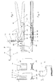
Ein Ausführungsbeispiel der Erfindung wird anhand der Figuren 1 bis 6 erläutert. Es zeigen:
- Fig. 1
- eine Ausführungsform der Handsicken/crimpzange in Seitenansicht (teilweise im Schnitt) mit den verschiedensten aufschiebbaren Gesenken
- Fig. 2
- Teilausschnitte als Draufsicht des unteren Teiles nach Fig. 1
- Fig. 3
- Anordnung eines aufgeschobenen und verschiebbar angeordneten Doppelfunktionsgesenkes für Boden- und Randsicken und eines in diesem Fall zur Arretierung dienenden gleichfalls aufgeschobenen Doppelfunktionsgesenkes für U-Profile und Randsicken zum Eindrücken von Bodensicken in ein eingelegtes U-Profil
- Fig. 4
- Anordnung eines aufgeschobenen Doppelfunktionsgesenkes für Boden- und Randsicken dessen Einschnitt sich gegenüber des Kerbsickenkeiles des gleichfalls aufgeschobenen und arretierten Doppelfunktionsgesenkes für Boden- und U-Profile befindet zum beidseitigen Drücken eines eingelegten doppelseitigen U-Profiles
- Fig. 5
- ein aufgeschobenes und arretiertes Doppelfunktionsgesenk für U-Profile und Randsicken, welches mit seiner Negativseite dem Kerbsickenkeil gegenüber angeordnet ist zum Verformen von U-Wandprofilen
- Fig. 6
- ein aufgeschobenes und arretiertes Crimpgesenk, welches gegenüber einem eingebrachten Crimpstanzteil angeordnet ist
- Fig. 1
- an embodiment of the hand beads / crimping pliers in side view (partially in section) with a variety of push-fit dies
- Fig. 2
- Partial cutouts as a top view of the lower part according to FIG. 1
- Fig. 3
- Arrangement of a slidable and slidably arranged double-function die for bottom and edge beads and a double-function die for U-profiles, which is also used for locking purposes, in this case for locking, and edge beads for pressing bottom beads into an inserted U-profile
- Fig. 4
- Arrangement of a pushed-on double-function die for floor and edge beads, the incision of which is located opposite the notched bead wedge of the double-action die for floor and U-profiles, which is also pushed on and locked, for pressing an inserted double-sided U-profile on both sides
- Fig. 5
- a slid-on and locked double-function die for U-profiles and edge beads, which is arranged with its negative side opposite the notched bead wedge for deforming U-wall profiles
- Fig. 6
- a pushed and locked crimping die, which is arranged opposite an inserted crimp stamped part
Nach Fig. 1 und 2 besteht die Handsicken/crimpzange aus einem statischen Teil, als Grundelement
1. Das aus U-förmigen Stahlblech bestehende, nach oben offen ausgebildeten Grundelement 1
ist im vorderen Teil so abgewinkelt und verjüngt sich so, daß durch die sich ergebenen Außenseiten
2 ein Befestigungs- und Führungsteil 3 entsteht. Der oberen Teil des Befestigungs-
und Führungsteiles 3 dient dabei zur Befestigung einer rechtwinklig ausgebildeten Gesenkaufnahme
4 mit einem L-förmigen Verschraubungsteil, und der untere Teil des Befestigungs-
und Führungsteiles 3 als Gleitaufnahme für einen aus Flachstahl bestehenden, mit einem
Kerbsickenkeil 5 fest verbundenen Schaft 6. Ein an der Oberseite der Handsickenzange befindlicher
Schraubbolzen 7, der fest an der Stirnseite des L-förmigen Teiles der Gesenkaufnahme
4 verschweißt ist, dient zur Aufnahme einer mit Arretierungsbohrungen 8 versehenen
Gesenkarretierung 9. Um die Gesenkarretierung 9 jederzeit auswechseln zu können bzw. sie
mit neuen Arretierungsbohrungen 8 versehen zu können, ist diese über eine Mutter 10 gesichert.
Um beim Aufschieben der jeweiligen Gesenke ein leichtes Einrasten des mit Arretierungsstiften
11 versehenen Doppelfunktionsgesenkes 12 für Wand- und Deckenprofile und
des Crimpgesenkes 13 zu ermöglichen, ist zwischen der Oberseite der Gesenkaufnahme 4 und
der Unterseite der Gesenkarretierung 9 eine Spiralfeder 14 mit Unterlegscheibe 15 eingebracht.1 and 2, the hand beads / crimping pliers consist of a static part, as a basic element
1. The basic element 1 made of U-shaped steel sheet and open at the top
is so angled in the front part and tapers so that through the resulting outer sides
2 a fastening and guiding
Zur Einleitung des jeweiligen Drückvorganges wird im U-Profil des Grundelementes 1 ein
gleichfalls U-förmiger Hebel 16 mit Griffelement aufgenommen.To initiate the respective pressing process, 1 is in the U-profile of the basic element
likewise U-shaped
Der U-förmige Hebel 16 ist in Richtung der Griffseite leicht gekröpft und seine Vorderseite
ist so ausgebildet, daß zwischen dem beidseitig im Grundelement 1 gelagerten und mit Unterlegscheiben
verschraubten Gelenkpunkt 17 und einem Verbindungsgelenkstift 18 als Drehpunkt,
ein Hebelarm entsteht, dessen Kräfte über eine doppelseitige Pleuelstange 19 über eine
Stiftschraube 20 auf den Schaft 6 und damit auf den Kerbsickenkeil 5 übertragen wird. Die
beidseitig an dem Schaft 6 anliegende Pleuelstange 19 ist durch Verwendung der Stiftschraube
20 jederzeit auswechselbar.The U-shaped
Ein gleichfalls im Grundelement 1 befindlicher Bolzen 21 dient einerseits dem Hebel 16 als
Anschlag und andererseits, wie der L-förmige Verschraubungsteil der Gesenkaufnahme 4, als
Führungselement für den Schaft 6. A
Die notwendige Stabilität im vorderen Arbeitsbereich der Handsickenzange ergibt sich durch
Verschraubung der Außenseiten 2 zusammen mit dem darin eingeschobenen L-förmigen Verschraubungsteil
der Gesenkaufnahme 4 mittels Verbindungsschrauben 22.The necessary stability in the front working area of the hand crimping tool results from
Screwing the
Nach Fig. 3 ist ein verschiebbares Doppelfunktionsgesenk 23 für Boden- und Randsicken über
eine Durchgangsführung 24 analog der Gesenkaufnahme 4 auf diese aufgeschoben. Außer der
beidseitig eingearbeiteten Gesenkaussparung 25 ist an der für die Sickung vorgesehenen Arbeitsseite,
d. h., gegenüber des Kerbsickenkeiles 5, eine Aussparung 26 eingearbeitet, so daß
das zur Bearbeitung vorgesehene handelsübliche C-Profil 27 zum Einbringen von Bodensicken
(für gewölbte Decken) eingelegt werden kann. Ein Doppelfunktionsgesenk 12 für
U-Profile und Randsicken übernimmt hierbei mit seiner flachen Seite über den in der Arretierungsbohrung
8 eingerasteten Arretierungsstift 11 die Arretierung.3 is a slidable double-function die 23 for bottom and edge beads over
a
Nach Fig. 4 wird zum Drücken von Doppelsicken im Randbereich eines C-Profiles 27 (zur
Herstellung von Unterbögen) das verschiebbare Doppelfunktionsgesenk 23 so aufgeschoben,
daß die glatte Seite mit der Gesenkaussparung 25 sich gegenüber des Kerbsickenkeiles 5 befindet
und die andere versetzte Aussparung 25 mit der Aussparung 26 gegenüber des Kerbsickenkeiles
28 des gleichfalls verändert aufgeschobenen und arretierten Doppelfunktionsgesenkes
12, angeordnet ist.4 is for pressing double beads in the edge region of a C-profile 27 (for
Production of lower arches) the slidable double-
Nach Fig. 5 wird das Doppelfunktionsgesenk 12 mit seiner flachen Seite und der Gesenkaussparung
29 gegenüber des Kerbsickenkeiles 5 zum Verformen von handelsüblichen U-Wandprofilen
30 in der vorderen Arretierungsbohrung 8 der Gesenkarretierung 9 fixiert.
Nach Fig. 6 ist eine weitere Möglichkeit zur universellen Verwendung der Sicken/crimpzange dargestellt,
in dem statt der Doppelfunktionsgesenke ein Crimpgesenk 13 auf die Gesenkaufnahme
4 aufgeschoben und über eine Arretierungsbohrung 8 der Gesenkarretierung 9 arretiert
wird. Gleichfalls wurde der Schaft 6 mit Kerbsickenkeil 5 ausgewechselt und durch einen
Schaft 6 mit Crimpkopf 31 als Stanzteil ersetzt. Das Crimpgesenk 13 ist dabei so ausgebildet,
daß das Arbeitsteil 32 so weit vorgezogen ist, daß ausreichend Platz für das zu bearbeitenden
Werkstück zur Verfügung steht.5, the double-
Claims (8)
- Universally usable hand-operated crimping pliers, a basic element (1) as a static part, for example made from U-shaped steel sheet, being angled and tapered on its front side in such a way that the parallel outer faces (2) thus obtained give rise to a fastening and guiding part (3), into which, on the one hand, is introduced in the upper part a rectangular and L-shaped swage receptacle (4) with a screw bolt (7), fixedly connected to the latter on the end face, as a holder for a swage locking device (9) for receiving swages provided with a locking pin (11) and, on the other hand, is introduced in the lower part a sliding receptacle which receives a shank (6) which consists of flat sheet and is fixedly connected, for example, to a notch-crimping wedge (5) and which is guided through the underside of the L-shaped part of the swage receptacle (4) and through a bolt (21) which also serves at the same time as a stop for a lever (16) having a grip element, force transmission taking place via a likewise U-shaped lever (16), the front side of which is designed in such a way as to give rise, between an articulation point (17) mounted in the basic element (1) and an articulated connecting pin (18) as centre of rotation, to a lever arm, the force of which can be transmitted to the shank (6) and therefore, for example, to the notch-crimping wedge (5) via a two-sided connecting rod (19) having a stud (20) as articulation point.
- Hand-operated crimping pliers according to Claim 1, characterized in that the swage locking device (9) is provided with one or more locking bores (8).
- Hand-operated crimping pliers according to Claims 1 and 2, characterized in that the swage locking device (9) is cranked slightly on the part drilled through for the screw bolt (7), so that moveability is further improved by a helical spring (14) received by the screw bolt (7) and having a washer (15) which is located between the swage locking device (9) and the top edge of the basic element (1).
- Hand-operated crimping pliers according to Claim 1, characterized in that the exchangeable shank (6) can likewise be fixedly provided with other tools, such as, for example, a crimping head (31).
- Hand-operated crimping pliers according to one or more of Claims 1 to 4, characterized in that the respective swage clearance (25; 29) of the swages, for example, double-function swages (12; 23), pushed via passage guides (24) onto the swage receptacle (4) corresponds to the opposite notch-crimping wedge (5).
- Hand-operated crimping pliers according to Claim 5, characterized in that the double-function swage (12) provided with a locking pin (11) has a swage clearance (29) on one side and a notch-crimping wedge (28) on the opposite side.
- Hand-operated crimping pliers according to Claim 5, characterized in that the double-function swage (23), if required arranged displaceably on the swage receptacle (4), is provided with swage clearances (25) on both sides, one side additionally having a clearance (26) so that the swage clearance (25) on this side is open upwards.
- Hand-operated crimping pliers according to one or more of Claims 1 to 7, characterized in that a shank (6) has, instead of a notch-crimping wedge (5), a crimping head (31) which corresponds to a working part (32) of the crimping swage (13), said working part being pushed on the swage receptacle (4) and locked and being lengthened in an L-shaped manner.
Applications Claiming Priority (2)
| Application Number | Priority Date | Filing Date | Title |
|---|---|---|---|
| DE19646785 | 1996-11-13 | ||
| DE19646785A DE19646785C1 (en) | 1996-11-13 | 1996-11-13 | Hand crimping tool with interchangeable die |
Publications (3)
| Publication Number | Publication Date |
|---|---|
| EP0843390A2 EP0843390A2 (en) | 1998-05-20 |
| EP0843390A3 EP0843390A3 (en) | 1998-06-03 |
| EP0843390B1 true EP0843390B1 (en) | 2000-11-15 |
Family
ID=7811471
Family Applications (1)
| Application Number | Title | Priority Date | Filing Date |
|---|---|---|---|
| EP97111216A Expired - Lifetime EP0843390B1 (en) | 1996-11-13 | 1997-07-03 | Universal manual crimping tool |
Country Status (2)
| Country | Link |
|---|---|
| EP (1) | EP0843390B1 (en) |
| DE (2) | DE19646785C1 (en) |
Families Citing this family (1)
| Publication number | Priority date | Publication date | Assignee | Title |
|---|---|---|---|---|
| GB2438467B (en) * | 2006-05-25 | 2010-12-29 | Blue Sky Access Ltd | A crimping tool for use on a metal roof panel |
Family Cites Families (6)
| Publication number | Priority date | Publication date | Assignee | Title |
|---|---|---|---|---|
| BE533170A (en) * | 1953-11-10 | |||
| DE7205611U (en) * | 1972-02-15 | 1972-05-04 | Huber & Suhner Ag | Clamping pliers especially for cable connections |
| DE2728454C3 (en) * | 1977-06-24 | 1981-06-25 | Fritz 6703 Limburghof Knebel | Pipe wrench |
| DE3105262A1 (en) * | 1981-02-13 | 1982-09-02 | Bessey & Sohn Gmbh & Co, 7000 Stuttgart | TOOL FORMING, PRESSING OR PERFORMING OTHER WORKING OPERATIONS USING PRESSURE |
| WO1984004475A1 (en) * | 1983-05-09 | 1984-11-22 | David Meikle | Forming tool |
| DD225655B1 (en) * | 1984-04-10 | 1987-07-08 | Adw Ddr | PRESS PLIERS FOR COMPRESSING PIPE OR HUEL SENSITIVE WORKPIECES |
-
1996
- 1996-11-13 DE DE19646785A patent/DE19646785C1/en not_active Expired - Fee Related
-
1997
- 1997-07-03 EP EP97111216A patent/EP0843390B1/en not_active Expired - Lifetime
- 1997-07-03 DE DE59702638T patent/DE59702638D1/en not_active Expired - Fee Related
Also Published As
| Publication number | Publication date |
|---|---|
| DE19646785C1 (en) | 1998-03-05 |
| EP0843390A2 (en) | 1998-05-20 |
| DE59702638D1 (en) | 2000-12-21 |
| EP0843390A3 (en) | 1998-06-03 |
Similar Documents
| Publication | Publication Date | Title |
|---|---|---|
| EP1445059B1 (en) | Function element, particularly fastening element and assembly part consisting of the function element and a sheet plate | |
| EP0682589B1 (en) | Interchangeable handle for slide blocks | |
| EP1554068B1 (en) | Stripping device | |
| DE202016007588U1 (en) | Screw-in aid for holding and aligning a screw | |
| EP2883658B1 (en) | Attachment for a pressing device | |
| EP3269509B1 (en) | Pliers for punching holes on trapezoidal profiles | |
| EP3988753A1 (en) | Furniture motor | |
| EP0156168A2 (en) | Tool for crimping, cutting, etc. with a linear working movement | |
| EP0843390B1 (en) | Universal manual crimping tool | |
| DE2540856C2 (en) | Method and device for striking a vehicle door | |
| DE4424493C2 (en) | Plier-like tool for the positive connection of sheet metal parts | |
| EP0158062A1 (en) | Tool for crimping, cutting, pressing and the like | |
| DE3021332A1 (en) | Connecting machine for two sheets - deforms softer sheet to force material into cut in harder sheet at joint position | |
| EP2295177A1 (en) | Tool assembly and groove drawing machine for producing grooves or depressions | |
| DE19816198C2 (en) | Riveting process and riveting device for riveting several workpieces made of different materials | |
| DE102015212839B3 (en) | Device for applying holes in sheet metal parts | |
| DE3920701A1 (en) | Stamping tool for producing workpieces with bevelled edges - obviates need for subsequent grinding operation | |
| EP3689545A1 (en) | Jaw for tensioning a workpiece | |
| EP4030103B1 (en) | Cooking hob with control housing | |
| EP1561533A1 (en) | Apparatus for cutting profiles | |
| EP2045041B1 (en) | Handling device for a tool holder with a guide device | |
| DE10259871B4 (en) | Hand-operated processing device using a parallel vise | |
| DE102008029668B3 (en) | Tool aggregate for keyseating machine, has feed bar comprising multiple saw tooth-like feed wedges that work against multiple saw tooth-like feed edges of knife holder, where knife holder is attached to feed wedge | |
| DE10054752A1 (en) | Universal crimping and perforating tool has crimping/perforating body rotated through 180 degrees for selecting tool function | |
| DE19505143C2 (en) | Chisel holder |
Legal Events
| Date | Code | Title | Description |
|---|---|---|---|
| PUAI | Public reference made under article 153(3) epc to a published international application that has entered the european phase |
Free format text: ORIGINAL CODE: 0009012 |
|
| PUAL | Search report despatched |
Free format text: ORIGINAL CODE: 0009013 |
|
| AK | Designated contracting states |
Kind code of ref document: A2 Designated state(s): DE FR GB IT NL SE |
|
| AX | Request for extension of the european patent |
Free format text: AL;LT;LV;RO;SI |
|
| AK | Designated contracting states |
Kind code of ref document: A3 Designated state(s): AT BE CH DE DK ES FI FR GB GR IE IT LI LU MC NL PT SE |
|
| AX | Request for extension of the european patent |
Free format text: AL;LT;LV;RO;SI |
|
| 17P | Request for examination filed |
Effective date: 19981103 |
|
| AKX | Designation fees paid |
Free format text: DE FR GB IT NL SE |
|
| RBV | Designated contracting states (corrected) |
Designated state(s): DE FR GB IT NL SE |
|
| 17Q | First examination report despatched |
Effective date: 19990202 |
|
| GRAG | Despatch of communication of intention to grant |
Free format text: ORIGINAL CODE: EPIDOS AGRA |
|
| GRAG | Despatch of communication of intention to grant |
Free format text: ORIGINAL CODE: EPIDOS AGRA |
|
| GRAG | Despatch of communication of intention to grant |
Free format text: ORIGINAL CODE: EPIDOS AGRA |
|
| GRAH | Despatch of communication of intention to grant a patent |
Free format text: ORIGINAL CODE: EPIDOS IGRA |
|
| GRAH | Despatch of communication of intention to grant a patent |
Free format text: ORIGINAL CODE: EPIDOS IGRA |
|
| GRAA | (expected) grant |
Free format text: ORIGINAL CODE: 0009210 |
|
| AK | Designated contracting states |
Kind code of ref document: B1 Designated state(s): DE FR GB IT NL SE |
|
| ITF | It: translation for a ep patent filed | ||
| ET | Fr: translation filed | ||
| REF | Corresponds to: |
Ref document number: 59702638 Country of ref document: DE Date of ref document: 20001221 |
|
| GBT | Gb: translation of ep patent filed (gb section 77(6)(a)/1977) |
Effective date: 20001212 |
|
| PLBE | No opposition filed within time limit |
Free format text: ORIGINAL CODE: 0009261 |
|
| STAA | Information on the status of an ep patent application or granted ep patent |
Free format text: STATUS: NO OPPOSITION FILED WITHIN TIME LIMIT |
|
| 26N | No opposition filed | ||
| REG | Reference to a national code |
Ref country code: GB Ref legal event code: IF02 |
|
| PGFP | Annual fee paid to national office [announced via postgrant information from national office to epo] |
Ref country code: GB Payment date: 20020610 Year of fee payment: 6 |
|
| PGFP | Annual fee paid to national office [announced via postgrant information from national office to epo] |
Ref country code: NL Payment date: 20020717 Year of fee payment: 6 Ref country code: FR Payment date: 20020717 Year of fee payment: 6 |
|
| PGFP | Annual fee paid to national office [announced via postgrant information from national office to epo] |
Ref country code: SE Payment date: 20020723 Year of fee payment: 6 |
|
| PGFP | Annual fee paid to national office [announced via postgrant information from national office to epo] |
Ref country code: DE Payment date: 20020920 Year of fee payment: 6 |
|
| PG25 | Lapsed in a contracting state [announced via postgrant information from national office to epo] |
Ref country code: GB Free format text: LAPSE BECAUSE OF NON-PAYMENT OF DUE FEES Effective date: 20030703 |
|
| PG25 | Lapsed in a contracting state [announced via postgrant information from national office to epo] |
Ref country code: SE Free format text: LAPSE BECAUSE OF NON-PAYMENT OF DUE FEES Effective date: 20030704 |
|
| PG25 | Lapsed in a contracting state [announced via postgrant information from national office to epo] |
Ref country code: NL Free format text: LAPSE BECAUSE OF NON-PAYMENT OF DUE FEES Effective date: 20040201 |
|
| PG25 | Lapsed in a contracting state [announced via postgrant information from national office to epo] |
Ref country code: DE Free format text: LAPSE BECAUSE OF NON-PAYMENT OF DUE FEES Effective date: 20040203 |
|
| GBPC | Gb: european patent ceased through non-payment of renewal fee |
Effective date: 20030703 |
|
| EUG | Se: european patent has lapsed | ||
| PG25 | Lapsed in a contracting state [announced via postgrant information from national office to epo] |
Ref country code: FR Free format text: LAPSE BECAUSE OF NON-PAYMENT OF DUE FEES Effective date: 20040331 |
|
| NLV4 | Nl: lapsed or anulled due to non-payment of the annual fee |
Effective date: 20040201 |
|
| REG | Reference to a national code |
Ref country code: FR Ref legal event code: ST |
|
| PG25 | Lapsed in a contracting state [announced via postgrant information from national office to epo] |
Ref country code: IT Free format text: LAPSE BECAUSE OF NON-PAYMENT OF DUE FEES;WARNING: LAPSES OF ITALIAN PATENTS WITH EFFECTIVE DATE BEFORE 2007 MAY HAVE OCCURRED AT ANY TIME BEFORE 2007. THE CORRECT EFFECTIVE DATE MAY BE DIFFERENT FROM THE ONE RECORDED. Effective date: 20050703 |