EP0843390B1 - Pince manuelle universelle - Google Patents
Pince manuelle universelle Download PDFInfo
- Publication number
- EP0843390B1 EP0843390B1 EP97111216A EP97111216A EP0843390B1 EP 0843390 B1 EP0843390 B1 EP 0843390B1 EP 97111216 A EP97111216 A EP 97111216A EP 97111216 A EP97111216 A EP 97111216A EP 0843390 B1 EP0843390 B1 EP 0843390B1
- Authority
- EP
- European Patent Office
- Prior art keywords
- swage
- hand
- crimping
- receptacle
- pliers according
- Prior art date
- Legal status (The legal status is an assumption and is not a legal conclusion. Google has not performed a legal analysis and makes no representation as to the accuracy of the status listed.)
- Expired - Lifetime
Links
Images


Classifications
-
- B—PERFORMING OPERATIONS; TRANSPORTING
- B26—HAND CUTTING TOOLS; CUTTING; SEVERING
- B26F—PERFORATING; PUNCHING; CUTTING-OUT; STAMPING-OUT; SEVERING BY MEANS OTHER THAN CUTTING
- B26F1/00—Perforating; Punching; Cutting-out; Stamping-out; Apparatus therefor
- B26F1/32—Hand-held perforating or punching apparatus, e.g. awls
- B26F1/36—Punching or perforating pliers
-
- B—PERFORMING OPERATIONS; TRANSPORTING
- B25—HAND TOOLS; PORTABLE POWER-DRIVEN TOOLS; MANIPULATORS
- B25B—TOOLS OR BENCH DEVICES NOT OTHERWISE PROVIDED FOR, FOR FASTENING, CONNECTING, DISENGAGING, OR HOLDING
- B25B7/00—Pliers; Other hand-held gripping tools with jaws on pivoted limbs; Details applicable generally to pivoted-limb hand tools
- B25B7/02—Jaws
-
- B—PERFORMING OPERATIONS; TRANSPORTING
- B25—HAND TOOLS; PORTABLE POWER-DRIVEN TOOLS; MANIPULATORS
- B25B—TOOLS OR BENCH DEVICES NOT OTHERWISE PROVIDED FOR, FOR FASTENING, CONNECTING, DISENGAGING, OR HOLDING
- B25B7/00—Pliers; Other hand-held gripping tools with jaws on pivoted limbs; Details applicable generally to pivoted-limb hand tools
- B25B7/12—Pliers; Other hand-held gripping tools with jaws on pivoted limbs; Details applicable generally to pivoted-limb hand tools involving special transmission means between the handles and the jaws, e.g. toggle levers, gears
-
- H—ELECTRICITY
- H01—ELECTRIC ELEMENTS
- H01R—ELECTRICALLY-CONDUCTIVE CONNECTIONS; STRUCTURAL ASSOCIATIONS OF A PLURALITY OF MUTUALLY-INSULATED ELECTRICAL CONNECTING ELEMENTS; COUPLING DEVICES; CURRENT COLLECTORS
- H01R43/00—Apparatus or processes specially adapted for manufacturing, assembling, maintaining, or repairing of line connectors or current collectors or for joining electric conductors
- H01R43/04—Apparatus or processes specially adapted for manufacturing, assembling, maintaining, or repairing of line connectors or current collectors or for joining electric conductors for forming connections by deformation, e.g. crimping tool
- H01R43/042—Hand tools for crimping
- H01R43/0421—Hand tools for crimping combined with other functions, e.g. cutting
-
- B—PERFORMING OPERATIONS; TRANSPORTING
- B26—HAND CUTTING TOOLS; CUTTING; SEVERING
- B26F—PERFORATING; PUNCHING; CUTTING-OUT; STAMPING-OUT; SEVERING BY MEANS OTHER THAN CUTTING
- B26F1/00—Perforating; Punching; Cutting-out; Stamping-out; Apparatus therefor
- B26F1/32—Hand-held perforating or punching apparatus, e.g. awls
- B26F1/36—Punching or perforating pliers
- B26F2001/365—Punching or perforating pliers hand held pliers with handles
Definitions
- the invention relates to a universally applicable hand crimping pliers, which are characterized by Interchangeability of different dies and pressing tools for versatile cold forming of sheet metal and U profiles, in particular ceiling and wall profiles or for example, also suitable for crimping.
- punch pliers are used to punch openings, especially in plastic cans (OS DE 195 05 613), known or a beading device for the production of beaded electrical Connections according to AS 1144804.
- plastic cans OS DE 195 05 613
- beading device for the production of beaded electrical Connections according to AS 1144804.
- AS 1144804 it is not with any of the known devices possible to insert appropriate beads in sheet metal U-profiles or the special beading device can also be used for other cold forming operations
- a shaping tool according to PCT document WO-A-84/04475 (closest prior art) is also known, which is suitable for work such as bending and cutting, and from drive parts that are movable and are attached centrally to a tool body.
- drive parts that are movable and are attached centrally to a tool body.
- additional parts that are Have each inserted into the butt and support block provided with the tool part the possible uses of the bending tool are considerably increased, however no thin-walled C and U profiles can be machined with this tool either do not produce double beads.
- the invention has therefore set itself the task of one for a wide variety of operations to develop the cold forming universally applicable hand beads / crimping pliers with the thin-walled Sheet metal and U profiles, e.g. appropriately prepared ceilings CD or U profiles, as they are common in drywall construction, to be able to work on the spot, that with it a vertical or horizontal bending and thus manufacture of any desired Radius is possible and which is also suitable for other operations suitable, for example for crimping.
- the object is achieved in that a basic element as a static part, for example made of U-shaped steel sheet, and angled on its front and is tapered so that the resulting parallel outer sides of a fastening and the guide part was created.
- a basic element as a static part, for example made of U-shaped steel sheet, and angled on its front and is tapered so that the resulting parallel outer sides of a fastening and the guide part was created.
- the fastening and guide part is one right-angled and L-shaped die receptacle with a face firmly attached to it Screw bolt as a holder for a die lock for mounting with a locking pin provided dies.
- a sliding mount in which a flat steel, for example shaft connected with a notched bead wedge is accommodated.
- the bottom serves here of the L-shaped part of the die holder and a bolt that simultaneously also used as a stop for a lever with a grip element, as a guide.
- the front one for power transmission also U-shaped lever is designed so that between a hinge point in the base element and a connecting hinge pin as a fulcrum A lever arm is created, the force of which is via a double-sided connecting rod with a stud as a hinge point, on the shaft and thus, for example, on the notched bead wedge is transmitted.
- the die lock is preferably with one or more locking holes provided and preferably on the part pierced for the bolt, to improve the locking process into the locking holes of the dies pushed onto the die holder, slightly cranked.
- a spiral spring picked up by the bolt, which is located between the die lock and the upper edge of the base element is also facilitated the locking process.
- the notched bead wedge is preferably either fixed or detachably connected to the shaft, so that at any time depending on the conditions of use, an interchangeability either of the notched bead wedge or at permanent connections of the entire shaft-pressing tool unit, is possible.
- the dies that can be pushed onto the die holder via passage guides, for example Double-function dies are preferably slidable onto the die holder in such a way that the respective one Die cutout corresponds to the opposite notched bead wedge. That is, through the Appropriate application and combination of the respective dies are the most varied Beads, such as edge and bottom beads for the production of wall and ceiling profiles, can be inserted.
- a double-function die provided with locking pins preferably has one on one side Die cutout and on the opposite side a notched bead wedge so that it in the respective pressing process either only as a locking device arranged in front of it Double-function die or serves with the die holder or your own Notched bead wedge itself can be used as a shaping tool.
- One on the die holder if necessary slidably arranged double-function die is preferably on both sides with die mounts Mistake. However, one side has an additional recess, so that the die recess this side is open at the top and so there is free space for the profile to be processed or for combination with other double function dies.
- the shaft is provided with a crimp head instead of a notched bead wedge and finds it a working part slid onto the die holder and extended with an L-shape locked crimping die use
- the hand crimping pliers are also used as crimping pliers changeable.
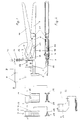
- the hand beads / crimping pliers consist of a static part, as a basic element 1.
- the basic element 1 made of U-shaped steel sheet and open at the top is so angled in the front part and tapers so that through the resulting outer sides 2 a fastening and guiding part 3 is created.
- the upper part of the attachment and guide part 3 is used to attach a rectangular die holder 4 with an L-shaped screw part, and the lower part of the fastening and guide part 3 as a sliding mount for an existing flat steel, with a Notch bead wedge 5 firmly connected shaft 6.
- the U-shaped lever 16 is slightly cranked towards the handle side and its front is designed so that between the bearings on both sides in the base element 1 and with washers screwed hinge point 17 and a connecting hinge pin 18 as a fulcrum, a lever arm arises, the forces of which are via a double-sided connecting rod 19 via a Stud 20 is transferred to the shaft 6 and thus to the notched bead wedge 5.
- the Connecting rod 19 resting on both sides of the shaft 6 is by using the stud screw 20 exchangeable at any time.
- a bolt 21, which is also located in the base element 1, serves on the one hand the lever 16 as Stop and on the other hand, as the L-shaped screw part of the die holder 4, as Guide element for the shaft 6.
- the necessary stability in the front working area of the hand crimping tool results from Screwing the outer sides 2 together with the L-shaped screw part inserted therein the die holder 4 by means of connecting screws 22.
- a dual function die 12 for U-profiles and edge beads take over with its flat side over the in the locking hole 8 locked locking pin 11 the locking.
- the slidable double-function die 23 is pushed on that the smooth side with the die recess 25 is opposite the notched bead wedge 5 and the other offset recess 25 with the recess 26 opposite the notch bead 28 of the double-function die, which has also been postponed and locked 12, is arranged.
- the double-function die 12 with its flat side and the die recess 29 opposite the notched bead wedge 5 for deforming commercially available U-wall profiles 30 fixed in the front locking hole 8 of the die lock 9.
- 6 shows a further possibility for universal use of the beads / crimping pliers, in which, instead of the double-function dies, a crimp die 13 on the die holder 4 pushed on and locked via a locking hole 8 of the die lock 9 becomes.
- the shaft 6 was replaced with notched bead wedge 5 and by one Shank 6 replaced with crimping head 31 as a stamped part.
- the crimping die 13 is designed so that the working part 32 is advanced so far that there is enough space for the work to be done Workpiece is available.
Landscapes
- Engineering & Computer Science (AREA)
- Mechanical Engineering (AREA)
- Life Sciences & Earth Sciences (AREA)
- Forests & Forestry (AREA)
- Manufacturing & Machinery (AREA)
- Gripping Jigs, Holding Jigs, And Positioning Jigs (AREA)
- Hand Tools For Fitting Together And Separating, Or Other Hand Tools (AREA)
- Connection Of Plates (AREA)
- Clamps And Clips (AREA)
Claims (8)
- Pince manuelle à moulurer/sertir universelle, dans laquelle un élément de base (1) servant de pièce statique, par exemple en tôle d'acier en forme de U, est coudé et rétréci à sa partie avant de telle sorte qu'une pièce de fixation et de guidage (3) soit créée par les côtés extérieurs (2) parallèles ainsi obtenus, dans la partie supérieure de laquelle d'une part un logement de matrice rectangulaire et en forme de L (4) est monté avec un boulon fileté (7) fixé fermement à celui-ci dans la partie frontale en tant que fixation pour un verrouillage de matrice (9) envue de recevoir une matrice pourvue d'une broche de verrouillage (11) et dans la partie inférieure de laquelle, d'autre part, est monté un logement de glissement, dans lequel est reçue une tige (6) en acier plat par exemple connectée fermement à une clavette à moulurer les encoches (5), qui est guidée par la face inférieure de la partie en forme de L du logement de matrice (4) ainsi que par un boulon (21), qui sert simultanément aussi de verrouillage pour un levier (16) avec un élément de prise, le transfert de force s'effectuant par l'intermédiaire d'un levier également en forme de U (16), dont la partie avant est conçue de telle sorte que l'on obtienne un bras de levier entre un point d'articulation (17) monté dans l'élément de base (1) et une broche d'articulation de connexion (18) servant de pivot, dont la force peut être transmise par une bielle double (19) ayant un goujon fileté (20) servant de point d'articulation à l'arbre (6) et ainsi par exemple à la clavette à moulurer les encoches (5).
- Pince manuelle à moulurer/sertir universelle selon la revendication 1, caractérisée en ce que le verrouillage de matrice (9) est pourvu d'un ou de plusieurs alésages de verrouillage (8).
- Pince manuelle à moulurer/sertir universelle selon la revendication 1 ou 2, caractérisée en ce que le verrouillage de matrice (9) est légèrement coudé sur la partie percée pour le boulon fileté (7), de sorte que la mobilité soit encore améliorée par un ressort spiral (14) reçu par un boulon fileté (7) avec une rondelle (15), qui se trouve entre le verrouillage de matrice (9) et l'arête supérieure de l'élément de base (1) .
- Pince manuelle à moulurer/sertir universelle selon la revendication 1, caractérisée en ce que l'arbre échangeable (6) peut également être pourvu d'autres outils fixés fermement, tels que par exemple une tête de sertissage (31).
- Pince manuelle à moulurer/sertir universelle selon l'une ou plusieurs des revendications 1 à 4, caractérisée en ce que l'évidement de matrice respectif (25; 29) de la matrice poussée par l'intermédiaire des guides de passage (24) sur le logement de matrice (4), par exemple la matrice à double fonction (12; 23), correspond à la clavette à moulurer les encoches (5) opposée.
- Pince manuelle à moulurer/sertir universelle selon la revendication 5, caractérisée en ce que la matrice à double fonction (12) pourvue d'une broche de verrouillage (11) présente d'un côté un évidement de matrice (29) et du côté opposé une clavette à moulurer les encoches (28).
- Pince manuelle à moulurer/sertir universelle selon la revendication 5, caractérisée en ce qu'en cas de besoin, la matrice à double fonction (23) disposée de manière mobile sur le logement de matrice (4) est pourvue des deux côtés d'évidements de matrice (25), un côté présentant en outre un évidement (26), de sorte que l'évidement de matrice (25) de ce côté soit ouvert vers le haut.
- Pince manuelle à moulurer/sertir universelle selon l'une ou plusieurs des revendications 1 à 7, caractérisée en ce qu'un arbre (6) présente à la place d'une clavette à moulurer les encoches (5) une tête de sertissage (31), qui correspond à une pièce de travail (32) de la matrice de sertissage (13) poussée et verrouillée sur lé logement de matrice (4), la pièce de travail (32) de la matrice de sertissage (13) étant prolongée en forme de L.
Applications Claiming Priority (2)
| Application Number | Priority Date | Filing Date | Title |
|---|---|---|---|
| DE19646785A DE19646785C1 (de) | 1996-11-13 | 1996-11-13 | Handsickenzange mit auswechselbarem Gesenk |
| DE19646785 | 1996-11-13 |
Publications (3)
| Publication Number | Publication Date |
|---|---|
| EP0843390A2 EP0843390A2 (fr) | 1998-05-20 |
| EP0843390A3 EP0843390A3 (fr) | 1998-06-03 |
| EP0843390B1 true EP0843390B1 (fr) | 2000-11-15 |
Family
ID=7811471
Family Applications (1)
| Application Number | Title | Priority Date | Filing Date |
|---|---|---|---|
| EP97111216A Expired - Lifetime EP0843390B1 (fr) | 1996-11-13 | 1997-07-03 | Pince manuelle universelle |
Country Status (2)
| Country | Link |
|---|---|
| EP (1) | EP0843390B1 (fr) |
| DE (2) | DE19646785C1 (fr) |
Families Citing this family (1)
| Publication number | Priority date | Publication date | Assignee | Title |
|---|---|---|---|---|
| GB2438467B (en) * | 2006-05-25 | 2010-12-29 | Blue Sky Access Ltd | A crimping tool for use on a metal roof panel |
Family Cites Families (6)
| Publication number | Priority date | Publication date | Assignee | Title |
|---|---|---|---|---|
| BE533170A (fr) * | 1953-11-10 | |||
| DE7205611U (de) * | 1972-02-15 | 1972-05-04 | Huber & Suhner Ag | Klemmzange insbesondere für Kabelverbindungen |
| DE2728454C3 (de) * | 1977-06-24 | 1981-06-25 | Fritz 6703 Limburghof Knebel | Rohrzange |
| DE3105262A1 (de) * | 1981-02-13 | 1982-09-02 | Bessey & Sohn Gmbh & Co, 7000 Stuttgart | Werkzeug zum verformen, druecken oder zur durchfuehrung anderer arbeitsgaenge unter anwendung von druck |
| WO1984004475A1 (fr) * | 1983-05-09 | 1984-11-22 | David Meikle | Outil de façonnage |
| DD225655B1 (de) * | 1984-04-10 | 1987-07-08 | Adw Ddr | Presszange zum zusammendruecken von rohr- oder huelsenfoermigen werkstuecken |
-
1996
- 1996-11-13 DE DE19646785A patent/DE19646785C1/de not_active Expired - Fee Related
-
1997
- 1997-07-03 EP EP97111216A patent/EP0843390B1/fr not_active Expired - Lifetime
- 1997-07-03 DE DE59702638T patent/DE59702638D1/de not_active Expired - Fee Related
Also Published As
| Publication number | Publication date |
|---|---|
| DE59702638D1 (de) | 2000-12-21 |
| EP0843390A3 (fr) | 1998-06-03 |
| DE19646785C1 (de) | 1998-03-05 |
| EP0843390A2 (fr) | 1998-05-20 |
Similar Documents
| Publication | Publication Date | Title |
|---|---|---|
| EP1445059B1 (fr) | Elément fonctionnel, notamment élément de fixation et ensemble de montage comprenant l'élément fonctionnel et une pièce de tôle | |
| EP1554068B1 (fr) | Dispositif d'arrachage | |
| DE202016007588U1 (de) | Einschraubhilfe zum Halten und Ausrichten einer Schraube | |
| EP0682589A1 (fr) | Poignee interchangeable pour cales coulissantes. | |
| EP2883658B1 (fr) | Accessoire pour un dispositif de presse | |
| EP3988753A1 (fr) | Entraînement pour meuble | |
| EP3269509B1 (fr) | Pince pour réaliser de troux sur des profiles à section trapézoïdale | |
| EP0156168A2 (fr) | Outil pour sertir, couper, presser etc. avec mouvement linéaire de travail | |
| EP0843390B1 (fr) | Pince manuelle universelle | |
| DE2540856C2 (de) | Verfahren und Vorrichtung zum Anschlagen einer Fahrzeugtür | |
| DE4424493C2 (de) | Zangenartiges Werkzeug zum formschlüssigen Verbinden von Blechteilen | |
| EP4434682A1 (fr) | Outil | |
| EP0158062A1 (fr) | Outil pour emboutir, couper, compresser ou similaire | |
| DE202004001662U1 (de) | Aufsatz für ein Presswerkzeug | |
| DE3021332A1 (de) | Vorrichtung zum verbinden wneigstens zweier bauteile durch ein schnitt-umform-verfahren | |
| EP2295177A1 (fr) | Agrégat d'outil et machine d'extraction de rainures pour la fabrication de rainures ou d'évidements | |
| DE19816198C2 (de) | Nietverfahren und Nieteinrichtung zum Vernieten von mehreren, aus unterschiedlichen Werkstoffen bestehenden Werkstücken | |
| DE102015212839B3 (de) | Vorrichtung zum Anbringen von Löchern in Blechteilen | |
| DE3920701A1 (de) | Werkzeuganordnung zur anbringung von schraegschnitten an blechen durch feinschneiden oder stanzen | |
| EP3689545A1 (fr) | Mâchoire de serrage permettant de serrer une pièce | |
| EP4030103B1 (fr) | Plaque de cuisson avec boîtier de commande | |
| EP1561533A1 (fr) | Dispositif pour couper des profils | |
| EP2045041B1 (fr) | Dispositif de manipulation pour un support d'outil doté d'un dispositif de guidage | |
| DE10259871B4 (de) | Handbetätigte Bearbeitungsvorrichtung unter Verwendung eines Parallelschraubstocks | |
| DE102008029668B3 (de) | Werkzeugaggregat und Maschine zum Herstellen von Nuten oder dergleichen |
Legal Events
| Date | Code | Title | Description |
|---|---|---|---|
| PUAI | Public reference made under article 153(3) epc to a published international application that has entered the european phase |
Free format text: ORIGINAL CODE: 0009012 |
|
| PUAL | Search report despatched |
Free format text: ORIGINAL CODE: 0009013 |
|
| AK | Designated contracting states |
Kind code of ref document: A2 Designated state(s): DE FR GB IT NL SE |
|
| AX | Request for extension of the european patent |
Free format text: AL;LT;LV;RO;SI |
|
| AK | Designated contracting states |
Kind code of ref document: A3 Designated state(s): AT BE CH DE DK ES FI FR GB GR IE IT LI LU MC NL PT SE |
|
| AX | Request for extension of the european patent |
Free format text: AL;LT;LV;RO;SI |
|
| 17P | Request for examination filed |
Effective date: 19981103 |
|
| AKX | Designation fees paid |
Free format text: DE FR GB IT NL SE |
|
| RBV | Designated contracting states (corrected) |
Designated state(s): DE FR GB IT NL SE |
|
| 17Q | First examination report despatched |
Effective date: 19990202 |
|
| GRAG | Despatch of communication of intention to grant |
Free format text: ORIGINAL CODE: EPIDOS AGRA |
|
| GRAG | Despatch of communication of intention to grant |
Free format text: ORIGINAL CODE: EPIDOS AGRA |
|
| GRAG | Despatch of communication of intention to grant |
Free format text: ORIGINAL CODE: EPIDOS AGRA |
|
| GRAH | Despatch of communication of intention to grant a patent |
Free format text: ORIGINAL CODE: EPIDOS IGRA |
|
| GRAH | Despatch of communication of intention to grant a patent |
Free format text: ORIGINAL CODE: EPIDOS IGRA |
|
| GRAA | (expected) grant |
Free format text: ORIGINAL CODE: 0009210 |
|
| AK | Designated contracting states |
Kind code of ref document: B1 Designated state(s): DE FR GB IT NL SE |
|
| ITF | It: translation for a ep patent filed | ||
| ET | Fr: translation filed | ||
| REF | Corresponds to: |
Ref document number: 59702638 Country of ref document: DE Date of ref document: 20001221 |
|
| GBT | Gb: translation of ep patent filed (gb section 77(6)(a)/1977) |
Effective date: 20001212 |
|
| PLBE | No opposition filed within time limit |
Free format text: ORIGINAL CODE: 0009261 |
|
| STAA | Information on the status of an ep patent application or granted ep patent |
Free format text: STATUS: NO OPPOSITION FILED WITHIN TIME LIMIT |
|
| 26N | No opposition filed | ||
| REG | Reference to a national code |
Ref country code: GB Ref legal event code: IF02 |
|
| PGFP | Annual fee paid to national office [announced via postgrant information from national office to epo] |
Ref country code: GB Payment date: 20020610 Year of fee payment: 6 |
|
| PGFP | Annual fee paid to national office [announced via postgrant information from national office to epo] |
Ref country code: NL Payment date: 20020717 Year of fee payment: 6 Ref country code: FR Payment date: 20020717 Year of fee payment: 6 |
|
| PGFP | Annual fee paid to national office [announced via postgrant information from national office to epo] |
Ref country code: SE Payment date: 20020723 Year of fee payment: 6 |
|
| PGFP | Annual fee paid to national office [announced via postgrant information from national office to epo] |
Ref country code: DE Payment date: 20020920 Year of fee payment: 6 |
|
| PG25 | Lapsed in a contracting state [announced via postgrant information from national office to epo] |
Ref country code: GB Free format text: LAPSE BECAUSE OF NON-PAYMENT OF DUE FEES Effective date: 20030703 |
|
| PG25 | Lapsed in a contracting state [announced via postgrant information from national office to epo] |
Ref country code: SE Free format text: LAPSE BECAUSE OF NON-PAYMENT OF DUE FEES Effective date: 20030704 |
|
| PG25 | Lapsed in a contracting state [announced via postgrant information from national office to epo] |
Ref country code: NL Free format text: LAPSE BECAUSE OF NON-PAYMENT OF DUE FEES Effective date: 20040201 |
|
| PG25 | Lapsed in a contracting state [announced via postgrant information from national office to epo] |
Ref country code: DE Free format text: LAPSE BECAUSE OF NON-PAYMENT OF DUE FEES Effective date: 20040203 |
|
| GBPC | Gb: european patent ceased through non-payment of renewal fee |
Effective date: 20030703 |
|
| EUG | Se: european patent has lapsed | ||
| PG25 | Lapsed in a contracting state [announced via postgrant information from national office to epo] |
Ref country code: FR Free format text: LAPSE BECAUSE OF NON-PAYMENT OF DUE FEES Effective date: 20040331 |
|
| NLV4 | Nl: lapsed or anulled due to non-payment of the annual fee |
Effective date: 20040201 |
|
| REG | Reference to a national code |
Ref country code: FR Ref legal event code: ST |
|
| PG25 | Lapsed in a contracting state [announced via postgrant information from national office to epo] |
Ref country code: IT Free format text: LAPSE BECAUSE OF NON-PAYMENT OF DUE FEES;WARNING: LAPSES OF ITALIAN PATENTS WITH EFFECTIVE DATE BEFORE 2007 MAY HAVE OCCURRED AT ANY TIME BEFORE 2007. THE CORRECT EFFECTIVE DATE MAY BE DIFFERENT FROM THE ONE RECORDED. Effective date: 20050703 |