EP0842815A2 - Aufnahmevorrichtung für Gegenstände in Fahrzeugen - Google Patents
Aufnahmevorrichtung für Gegenstände in Fahrzeugen Download PDFInfo
- Publication number
- EP0842815A2 EP0842815A2 EP97111087A EP97111087A EP0842815A2 EP 0842815 A2 EP0842815 A2 EP 0842815A2 EP 97111087 A EP97111087 A EP 97111087A EP 97111087 A EP97111087 A EP 97111087A EP 0842815 A2 EP0842815 A2 EP 0842815A2
- Authority
- EP
- European Patent Office
- Prior art keywords
- holder
- receiving device
- housing
- legs
- recess
- Prior art date
- Legal status (The legal status is an assumption and is not a legal conclusion. Google has not performed a legal analysis and makes no representation as to the accuracy of the status listed.)
- Granted
Links
- 238000003780 insertion Methods 0.000 claims description 12
- 230000037431 insertion Effects 0.000 claims description 12
- 239000000463 material Substances 0.000 claims description 8
- 238000005452 bending Methods 0.000 claims description 5
- 239000002184 metal Substances 0.000 claims description 4
- 230000006835 compression Effects 0.000 claims description 3
- 238000007906 compression Methods 0.000 claims description 3
- 239000012858 resilient material Substances 0.000 claims description 3
- 239000002131 composite material Substances 0.000 claims description 2
- 238000004519 manufacturing process Methods 0.000 description 5
- 238000009434 installation Methods 0.000 description 4
- 230000002349 favourable effect Effects 0.000 description 2
- 230000001133 acceleration Effects 0.000 description 1
- 230000009286 beneficial effect Effects 0.000 description 1
- 235000013361 beverage Nutrition 0.000 description 1
- 230000000881 depressing effect Effects 0.000 description 1
- 230000035622 drinking Effects 0.000 description 1
- 239000007788 liquid Substances 0.000 description 1
- 238000003825 pressing Methods 0.000 description 1
- 230000000630 rising effect Effects 0.000 description 1
- 238000005096 rolling process Methods 0.000 description 1
- 238000003860 storage Methods 0.000 description 1
- XLYOFNOQVPJJNP-UHFFFAOYSA-N water Substances O XLYOFNOQVPJJNP-UHFFFAOYSA-N 0.000 description 1
Images

Classifications
-
- B60K35/50—
-
- B—PERFORMING OPERATIONS; TRANSPORTING
- B60—VEHICLES IN GENERAL
- B60N—SEATS SPECIALLY ADAPTED FOR VEHICLES; VEHICLE PASSENGER ACCOMMODATION NOT OTHERWISE PROVIDED FOR
- B60N3/00—Arrangements or adaptations of other passenger fittings, not otherwise provided for
- B60N3/10—Arrangements or adaptations of other passenger fittings, not otherwise provided for of receptacles for food or beverages, e.g. refrigerated
- B60N3/102—Arrangements or adaptations of other passenger fittings, not otherwise provided for of receptacles for food or beverages, e.g. refrigerated storable or foldable in a non-use position
Definitions
- the invention relates to a receiving device for objects, in particular Vessels, in vehicles with a holder that has a receiving area has, and with a housing with an outwardly opening insertion opening, the holder being insertable into the housing and the receiving area the holder at least one recess as a receptacle for the objects having.
- Such receptacles are widely used in vehicles kind known. They ensure that objects in spite of the Operation of the vehicles - due to e.g. Accelerations - occurring Movements are held securely in place.
- Appropriate Cradles are e.g. used as a cup holder in motor vehicles. This gives the driver and other occupants the opportunity given to take drinks while driving without resealable Having to use vessels and without being at risk that a liquid in an open container while driving in the event of an unsafe position of the container into the vehicle interior steps out.
- the recess is more or less adapted
- the height at which the vessels are supported is important.
- the support height is too low, tilting movements can not be adequately absorbed and the Mug threatens to fall over. Therefore, known receptacles for Objects in vehicles have a not inconsiderable overall height.
- Another known embodiment of a cup holder provides this to integrate into the center console of a vehicle and with one as a flap trained lid to provide.
- This embodiment has the disadvantage on that even if the holder is not used, a lot of installation space, the e.g. for instruments, controls or small parts storage is required in the vehicle is lost because the cup holder - tied to the base the objects to be supported - a large installation area in the vehicle center console claimed.
- the invention has for its object a receiving device for objects to deliver in vehicles with a holder which cradle despite the low installation height and thus the small space required a large support height for securely supporting and holding the objects having.
- the inside height of the housing, the one Measure of the space requirement of the receiving device when not in use is chosen to be very low. That for a high functionality of the device decisive support height of the holder, however, only unfolds when the Holder leaves its rest position and assumes a position in which it is suitable is to pick up objects.
- a recording device according to the invention With a recording device according to the invention becomes a very high functionality at the same time minimal space to be kept.
- a recording device according to the invention can be used equally in all types of vehicles on land, in the air and in water. Even when the cockpit and / or Interior conditions do not have to with the present invention onto a receiving device for objects, e.g. Vessels, small parts of any Type, telecommunications equipment or the like, are waived.
- objects e.g. Vessels, small parts of any Type, telecommunications equipment or the like, are waived.
- the holder contrary to one specified above State of the art with a loadable from above, with a lid provided and thus concealable holder - can be inserted into a housing.
- the holder is a rotating component and around a substantially vertical axis rotatably insertable into the housing.
- the holder is formed by a drawer component insertable into the housing.
- the housing itself can be in a very simple manner as a tubular or frame-shaped Shaft if it is on the opposite of the insertion opening Side is open.
- the lower leg is a bottom plate. This is how to securely pick up the object to be held guaranteed both downwards and sideways. Especially to accommodate conical objects or to improve the The edge of the recess can be inserted conically be trained.
- the legs of the "U” or “V” of the holder are one Component connected together. Manufacturing and assembly effort for such a device is minimized. Nevertheless, it can be used in certain applications also be advantageous if the tavern of the "U” or “V” of the holder are connected to each other via a hinge element.
- Both of the above Embodiments are preferably one or both legs of the "U” or “V” of the holder resiliently moving its free ends away from each other acted upon.
- the one or the legs of the "U” or “V” of the holder Spring force can be achieved by a compression spring - e.g.
- At least one of the taverns of the "U” or “V” of the holder is made of metal or a composite. It it is also conceivable to advantageously use a plastic for this.
- the use of different materials for the holder's legs can be special then be interesting and beneficial if the two legs are not are connected to form a single component.
- the choice of material can then depending on the most favorable material properties for the respective element to be hit.
- the at least one recess in the Recording area of the holder as a recording for those to be held or supported Objects.
- this increase extends approximately axially to the associated recess and runs completely or partially around the edge of this recess.
- the at least one recess can generally round Adjusted base and cross-sectional area of the objects to be picked up be.
- the recesses can also be quadrangular or polygonal, and offers a aforementioned increase in the edge of the at least one recess especially when the receiving area of the holder against a is inclined as a footprint for the object serving base plate.
- the holder has at least one stop, which in Operating position with at least one respective recess or body edge of the housing is engaged.
- the housing has at least one Has stop that in the operating position with at least one respective recess or body edge, e.g. the hinge element of the holder is engaged.
- the stop e.g. in a particularly simple manner, the stop by an indented Be formed part of the housing, but in which embodiment disassembly of the holder and housing is difficult.
- the holder preferably has one arranged at the free end of a leg Front plate with which the insertion opening of the housing can be covered is. It is advisable that the front plate end stop for the insertion of the Holder is in the housing and can be placed against a front frame of the housing is.
- a handle is preferably integrated in the front panel so that the holder brought into its operating position by pulling it out of the housing can be.
- the structure of the receiving device according to the invention is particularly simple, when the holder is slid in the housing.
- Advantageous, however in the Manufacturing is more complex, the provision of a rolling bearing between the holder and housing, for example with the help of rollers.
- the holder in the inserted state in the housing preferably securable.
- This securing of the position is, in a particularly advantageous manner, a latching device.
- Such a position securing is particularly necessary when the holder can be inserted into the housing against a spring force. The application of such Spring force caused by e.g.
- the housing of the receiving device is preferably in an instrument panel, a center console or an interior paneling of a motor vehicle can be installed.
- the housing can also an integral part of an instrument panel, a center console or an interior paneling of a motor vehicle for completion the receiving device, it would then only be necessary to in the holder to insert the intended housing slot.
- the housing shaft is simply covered by a cover or for others Use devices or devices.
- This articulated connection can be made without any loss of functionality however also in a distance from the connection area of the "U” or “V” Area.
- the latter can e.g. then particularly advantageous be when the receiving area of the holder and the base plate inclusive further holder elements in the connection area of the "U” or “V” due desired different material properties from different Materials exist.
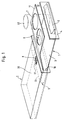
- the receiving device for objects shown in Figure 1 with a holder has a U-shaped holder 1 designed as a drawer component, which in a housing 2 is used.
- the housing 2 is used to attach the holder 1 in a vehicle and is for example in an instrument panel or one Passenger seat trim installed.
- the holder 1 which is slidably guided in the housing, it has one molded on a front panel 4 handle 5.
- the front panel 4 comes in the inserted State of the holder 1 on a front frame 6 of the housing 2 for Attack.
- the holder is pulled out, it is used in a recess 31 in a housing cover 30 of the housing 2 engaging stop 8 as a fuse to prevent the holder from being pulled out unintentionally the housing.
- the stop 8 serves as resistance to an unintentional Slide the holder into the housing. In its pulled out Position (operating position), the holder 1 is thus secured in position.
- a bottom plate 3 designed as a lower leg of the U-shaped holder 1 serves to park an object 40.
- the object 40 which is in this Embodiment is cylindrical and, for example, a drinking vessel can, is in a in the upper leg of the holder 1 in a receiving area 11 existing recess 7 used.
- a high stability of the The object 40 is supported by a large support height between the base plate 3 and recording area 11 reached.
- Holder 1 is a built-in part from a stamped, bent and folded Made of metal strips. Holder 1 could, for. B. also a plastic part the same Shape and with appropriate spring properties.
- the holder 1 out of the housing 2 is due to the spring action an automatic movement of the two legs of the holder in opposite directions Direction, forming an opening 12. So there is a big one Support height for the objects to be held with only a small installation height the receiving device in the vehicle.
- Inserting or removing the holder 1 into or out of the housing 2 is very easy with the top of the bar or the receiving area down 11 execute, whereby stop 8 and recess 31 except Intervention come.
- FIG. 2 Another embodiment of a recording device according to the invention is shown in Figure 2. Corresponding components are the same Provide reference numerals.
- holder 1 is V-shaped, the connection of the lower Leg with the upper leg using a hinge element 22 is realized.
- the recesses are inclined relative to the base plate 3 7 at its edge down the slope with ridges 25 for improvement the stability, not shown, from above into the recesses 7 provided items to be imported.
- a stop 23 secures the holder 1 against unintentional pulling out out of the housing 2.
- the stop 23 is by pushing out a segment a housing side wall 20 is formed.
- a corresponding stop can also be provided on a housing side wall 21.
- a backup prevents the holder 1 from accidentally sliding into the housing 2 due to the fact that it rests against the upper inner edge of the insertion opening 10 with spring force, outward rising upper leg of the V-shaped Holder.
Abstract
Description
- Figur 1
- eine erfindungsgemäße Aufnahmevorrichtung in perspektivischer Darstellung und
- Figur 2
- eine weitere Ausführungsform einer erfindungsgemäßen Vorrichtung in perspektivischer Darstellung.
Claims (34)
- Aufnahmevorrichtung für Gegenstände, insbesondere Gefäße, in Fahrzeugen mit einem Halter, der einen Aufnahmebereich aufweist, und mit einem Gehäuse mit einer nach außen hin mündenden Einführöffnung, wobei der Halter in das Gehäuse einführbar ist und der Aufnahmebereich des Halters zumindest eine Ausnehmung als Aufnahme für die Gegenstände aufweist, dadurch gekennzeichnet, daß der Halter (1) etwa U- oder V-förmig mit übereinanderliegenden Schenkeln ausgebildet ist und mit dem Verbindungsbereich (9) desU
 oder
oder
- Aufnahmevorrichtung nach Anspruch 1, dadurch gekennzeichnet, daß der Halter ein Drehbauteil ist und sich um eine im wesentlichen vertikale Achse drehend in das Gehäuse einführbar ist.
- Aufnahmevorrichtung nach Anspruch 1, dadurch gekennzeichnet, daß der Halter (1) ein Schubladenbauteil ist und durch Einschieben in das Gehäuse (2) einführbar ist.
- Aufnahmevorrichtung nach einem der vorhergehenden Ansprüche, dadurch gekennzeichnet, daß das Gehäuse (2) einen auf der der Einführöffnung (10) gegenüberliegenden Seite offenen Schacht bildet.
- Aufnahmevorrichtung nach einem der vorhergehenden Ansprüche, dadurch gekennzeichnet, daß die zumindest eine Ausnehmung (7) des Halters (1) in dem oberen Schenkel des
- Aufnahmevorrichtung nach einem der vorhergehenden Ansprüche, dadurch gekennzeichnet, daß der Rand der zumindest einen Ausnehmung (7) konisch ausgebildet ist.
- Aufnahmevorrichtung nach einem der vorhergehenden Ansprüche, dadurch gekennzeichnet, daß die Schenkel des
- Aufnahmevorrichtung nach einem der Ansprüche 1 bis 6, dadurch gekennzeichnet, daß die Schenkel des
- Aufnahmevorrichtung nach einem der vorhergehenden Ansprüche, dadurch gekennzeichnet, daß ein oder beide Schenkel des
- Aufnahmevorrichtung nach Anspruch 9, dadurch gekennzeichnet, daß der oder die Schenkel des
- Aufnahmevorrichtung nach einem der Ansprüche 9 oder 10, dadurch gekennzeichnet, daß die Schenke des
- Aufnahmevorrichtung nach einem der vorhergehenden Ansprüche, dadurch gekennzeichnet, daß zumindest einer der Schenke des
- Aufnahmevorrichtung nach einem der vorhergehenden Ansprüche, dadurch gekennzeichnet, daß zumindest einer der Schenkel des
- Aufnahmevorrichtung nach einem der vorhergehenden Ansprüche, dadurch gekennzeichnet, daß zumindest einer der Schenkel des
- Aufnahmevorrichtung nach einem der vorhergehenden Ansprüche, dadurch gekennzeichnet, daß der Halter (1) aus einem gestanzten und gekanteten und/oder gebogenen plattenförmigen Material besteht.
- Aufnahmevorrichtung nach einem der vorhergehenden Ansprüche, dadurch gekennzeichnet, daß der Rand der zumindest einen Ausnehmung (7) mit einer Erhöhung (25) versehen ist.
- Aufnahmevorrichtung nach Anspruch 16, dadurch gekennzeichnet, daß die Erhöhung (25) sich etwa axial zu der zugehörigen Ausnehmung (7) erstreckt.
- Aufnahmevorrichtung nach einem der Ansprüche 16 oder 17, dadurch gekennzeichnet, daß die Erhöhung (25) ganz oder teilweise an dem Rand der zugehörigen Ausnehmung (7) umläuft
- Aufnahmevorrichtung nach einem der vorhergehenden Ansprüche dadurch gekennzeichnet, daß der Halter (1) und/oder das Gehäuse (2) zumindest einen Anschlag besitzt, gegen den oder in dem der Halter (1) in Betriebsstellung anlegbar oder arretierbar ist.
- Aufnahmevorrichtung nach Anspruch 19, dadurch gekennzeichnet, daß der Halter (1) zumindest einen Anschlag (8) besitzt, der in Betriebsstellung mit zumindest einer jeweiligen Aussparung (31) oder Körperkante des Gehäuses (2) in Eingriff ist.
- Aufnahmevorrichtung nach einem der Ansprüche 19 oder 20, dadurch gekennzeichnet, daß das Gehäuse (2) zumindest einen Anschlag (23) besitzt, der in Betriebsstellung mit zumindest einer jeweiligen Aussparung oder Körperkante (Scharnierelement 22) des Halters (1) in Eingriff ist.
- Aufnahmevorrichtung nach einem der vorhergehenden Ansprüche, dadurch gekennzeichnet, daß der Halter (1) eine an dem freien Ende eines Schenkels angeordnete Frontplatte (4) aufweist, mit der die Einführöffnung (10) des Gehäuses (2) abdeckbar ist.
- Aufnahmevorrichtung nach Anspruch 22, dadurch gekennzeichnet, daß die Frontplatte (4) Endanschlag für das Einführen des Halters (1) in das Gehäuse (2) ist und gegen einen Frontrahmen (6) des Gehäuses (2) anlegbar ist.
- Aufnahmevorrichtung nach einem der Ansprüche 22 oder 23, dadurch gekennzeichnet, daß in der Frontplatte (4) ein Griff (5) integriert ist.
- Aufnahmevorrichtung nach einem der vorhergehenden Ansprüche, dadurch gekennzeichnet, daß der Halter (1) in dem Gehäuse (2) gleitgeführt ist.
- Aufnahmevorrichtung nach einem der Ansprüche 1 bis 24, dadurch gekennzeichnet, daß der Halter (1) in dem Gehäuse (2) wälzlagergeführt ist.
- Aufnahmevorrichtung nach einem der vorhergehenden Ansprüche, dadurch gekennzeichnet, daß der Halter (1) im eingeführten Zustand in dem Gehäuse (2) lagesicherbar ist.
- Aufnahmevorrichtung nach Anspruch 27, dadurch gekennzeichnet, daß die Lagesicherung eine Rastvorrichtung ist.
- Aufnahmevorrichtung nach einem der Ansprüche 27 oder 28, dadurch gekennzeichnet, daß der Halter (1) gegen eine Federkraft in das Gehäuse (2) einführbar ist.
- Aufnahmevorrichtung nach einem der vorhergehenden Ansprüche, dadurch gekennzeichnet, daß der Halter (1) motorisch in dem Gehäuse (2) bewegbar ist.
- Aufnahmevorrichtung nach einem der vorhergehenden Ansprüche, dadurch gekennzeichnet, daß das Gehäuse (2) in eine Instrumententafel, eine Mittelkonsole oder eine Innenverkleidung eines Kraftfahrzeugs einbaubar ist.
- Aufnahmevorrichtung nach einem der Ansprüche 1 bis 30, dadurch gekennzeichnet, daß das Gehäuse (2) integraler Bestandteil einer Instrumententafel, einer Mittelkonsole oder einer Innenverkleidung eines Kraftfahrzeugs ist.
- Aufnahmevorrichtung nach einem der vorhergehenden Ansprüche, dadurch gekennzeichnet, daß die gelenkige Verbindung der Schenke des
- Aufnahmevorrichtung nach einem der Ansprüche 1 bis 32, dadurch gekennzeichnet, daß die gelenkige Verbindung der Schenke des
Applications Claiming Priority (2)
| Application Number | Priority Date | Filing Date | Title |
|---|---|---|---|
| DE19646778 | 1996-11-13 | ||
| DE19646778A DE19646778A1 (de) | 1996-11-13 | 1996-11-13 | Aufnahmevorrichtung für Gegenstände in Fahrzeugen |
Publications (3)
| Publication Number | Publication Date |
|---|---|
| EP0842815A2 true EP0842815A2 (de) | 1998-05-20 |
| EP0842815A3 EP0842815A3 (de) | 1998-12-02 |
| EP0842815B1 EP0842815B1 (de) | 2002-10-02 |
Family
ID=7811466
Family Applications (1)
| Application Number | Title | Priority Date | Filing Date |
|---|---|---|---|
| EP97111087A Expired - Lifetime EP0842815B1 (de) | 1996-11-13 | 1997-07-03 | Aufnahmevorrichtung für Gegenstände in Fahrzeugen |
Country Status (3)
| Country | Link |
|---|---|
| EP (1) | EP0842815B1 (de) |
| DE (2) | DE19646778A1 (de) |
| ES (1) | ES2184930T3 (de) |
Cited By (2)
| Publication number | Priority date | Publication date | Assignee | Title |
|---|---|---|---|---|
| WO2004039679A2 (de) * | 2002-10-29 | 2004-05-13 | Trw Automotive Electronics & Components Gmbh & Co. Kg | Getränkehalter |
| US10737636B2 (en) * | 2018-01-31 | 2020-08-11 | Shanghai Yanfeng Jinqiao Automotive Trim Systems Co. Ltd. | Vehicle interior component |
Families Citing this family (8)
| Publication number | Priority date | Publication date | Assignee | Title |
|---|---|---|---|---|
| DE19906052B4 (de) * | 1999-02-12 | 2011-04-14 | Volkswagen Ag | Ablagevorrichtung in einer Schalttafel eines Kraftfahrzeuges |
| DE10023778A1 (de) * | 2000-05-15 | 2001-11-22 | Volkswagen Ag | Abdeckung für ein Staufach in einem Innenraumausstattungsteil eines Kraftfahrzeugs |
| DE102005035676A1 (de) * | 2004-12-24 | 2006-07-06 | Faurecia Innenraum Systeme Gmbh | Halter zur Aufnahme und Entnahme von Gebrauchs-Gegenständen |
| DE102005035674A1 (de) * | 2004-12-24 | 2006-07-06 | Faurecia Innenraum Systeme Gmbh | Halter für Gebrauchs-Gegenstände |
| DE102006043130B4 (de) * | 2006-09-14 | 2014-10-09 | Faurecia Innenraum Systeme Gmbh | Halter für Gebrauchs-Gegenstände |
| FR2909330A3 (fr) * | 2006-12-05 | 2008-06-06 | Renault Sas | Accessoire de vehicule pour le rangement de recipients, comprenant un support agence en tiroir escammotable a l'interieur d'un logement menage dans un element d'habillage interieur du vehicule. |
| DE102007029130B4 (de) | 2007-06-25 | 2010-11-25 | Faurecia Innenraum Systeme Gmbh | Halter für Gebrauchs-Gegenstände |
| DE102015210976B4 (de) | 2015-06-15 | 2019-05-23 | Bos Gmbh & Co. Kg | Vorrichtung zur Halterung wenigstens eines Behältnisses in einem Fahrzeuginnenraum sowie Armlehneneinheit |
Citations (6)
| Publication number | Priority date | Publication date | Assignee | Title |
|---|---|---|---|---|
| US4728018A (en) * | 1987-06-15 | 1988-03-01 | General Motors Corporation | Beverage holder for vehicle |
| US4783037A (en) * | 1987-08-10 | 1988-11-08 | Prince Corporation | Container holder for a vehicle |
| US5228611A (en) * | 1990-05-11 | 1993-07-20 | Toyoda Gosei Co., Ltd. | Container holder |
| US5379978A (en) * | 1994-02-04 | 1995-01-10 | Manchester Plastics | Vehicular convertible cupholder |
| EP0633162A1 (de) * | 1993-07-08 | 1995-01-11 | Manchester Plastics | Kraftbetätigter Becherhalter |
| DE4415732A1 (de) * | 1994-05-04 | 1995-11-09 | Happich Gmbh Gebr | Armlehne zwischen zwei nebeneinander angeordneten Sitzen eines Kraftfahrzeugs |
-
1996
- 1996-11-13 DE DE19646778A patent/DE19646778A1/de not_active Withdrawn
-
1997
- 1997-07-03 EP EP97111087A patent/EP0842815B1/de not_active Expired - Lifetime
- 1997-07-03 DE DE59708368T patent/DE59708368D1/de not_active Expired - Fee Related
- 1997-07-03 ES ES97111087T patent/ES2184930T3/es not_active Expired - Lifetime
Patent Citations (6)
| Publication number | Priority date | Publication date | Assignee | Title |
|---|---|---|---|---|
| US4728018A (en) * | 1987-06-15 | 1988-03-01 | General Motors Corporation | Beverage holder for vehicle |
| US4783037A (en) * | 1987-08-10 | 1988-11-08 | Prince Corporation | Container holder for a vehicle |
| US5228611A (en) * | 1990-05-11 | 1993-07-20 | Toyoda Gosei Co., Ltd. | Container holder |
| EP0633162A1 (de) * | 1993-07-08 | 1995-01-11 | Manchester Plastics | Kraftbetätigter Becherhalter |
| US5379978A (en) * | 1994-02-04 | 1995-01-10 | Manchester Plastics | Vehicular convertible cupholder |
| DE4415732A1 (de) * | 1994-05-04 | 1995-11-09 | Happich Gmbh Gebr | Armlehne zwischen zwei nebeneinander angeordneten Sitzen eines Kraftfahrzeugs |
Cited By (3)
| Publication number | Priority date | Publication date | Assignee | Title |
|---|---|---|---|---|
| WO2004039679A2 (de) * | 2002-10-29 | 2004-05-13 | Trw Automotive Electronics & Components Gmbh & Co. Kg | Getränkehalter |
| WO2004039679A3 (de) * | 2002-10-29 | 2004-07-22 | Trw Automotive Electron & Comp | Getränkehalter |
| US10737636B2 (en) * | 2018-01-31 | 2020-08-11 | Shanghai Yanfeng Jinqiao Automotive Trim Systems Co. Ltd. | Vehicle interior component |
Also Published As
| Publication number | Publication date |
|---|---|
| ES2184930T3 (es) | 2003-04-16 |
| DE59708368D1 (de) | 2002-11-07 |
| DE19646778A1 (de) | 1998-05-14 |
| EP0842815B1 (de) | 2002-10-02 |
| EP0842815A3 (de) | 1998-12-02 |
Similar Documents
| Publication | Publication Date | Title |
|---|---|---|
| EP0764558B1 (de) | Einbau-Vorrichtung insbesondere für Fahrzeuge | |
| EP1093962B1 (de) | Halter für einen Getränkebehälter | |
| EP0667258A1 (de) | Vorrichtung zum Halten von Getränkebehältern, Trinkgefässen oder dgl. | |
| EP0842815B1 (de) | Aufnahmevorrichtung für Gegenstände in Fahrzeugen | |
| DE102004014291B4 (de) | Haltevorrichtung zum lösbaren Halten von Gegenständen | |
| DE10234715A1 (de) | Drehbeweglicher Körper mit Entrastelement | |
| DE10043720B4 (de) | Halter für Gefäße | |
| DE19616774A1 (de) | Trinkgefäßhalter für Fahrzeuge | |
| DE10155798A1 (de) | Einbaukombination für ein Fortbewegungsmittel | |
| DE10121979A1 (de) | Haltevorrichtung für ein in einem Fahrzeug mitzuführendes Behältnis | |
| DE60204774T2 (de) | Konsolenkasten Anordnung | |
| WO2001074621A1 (de) | Halter für einen getränkebehälter | |
| DE4432036A1 (de) | Halterung für Hohlgefäße, insbesondere Getränkegefäße | |
| DE102014016230B4 (de) | Ablagefach eines Fahrzeugs | |
| DE19825795A1 (de) | Vorrichtung in der Form einer Kassette zur Aufnahme/Halterung von Behältnissen | |
| WO2000012373A2 (de) | Seitenplanenaufhängung | |
| DD297933A5 (de) | Tastenelement mit daempfungsfedern | |
| EP0779178B1 (de) | Vorrichtung in der Form einer Kassette zur Aufnahme/Halterung von Behältnissen | |
| EP1238854B1 (de) | Halterungsvorrichtung für Trinkgefässe in Kraftfahrzeugen | |
| DE102010041741B4 (de) | Vorrichtung zum Verschließen eines Fachs und Fach für ein Fahrzeug | |
| DE102015208748A1 (de) | Ablagefach mit einem Deckel | |
| DE102009030517B4 (de) | Haltevorrichtung | |
| DE102008044151A1 (de) | Getränkeautomat | |
| DE4427868C2 (de) | Behältnis, insbesondere Ascher für Fahrzeuge | |
| EP1298349A2 (de) | Vorrichtung zum gedämpften Einzug von beweglichen Bauteilen in eine Endlage |
Legal Events
| Date | Code | Title | Description |
|---|---|---|---|
| PUAI | Public reference made under article 153(3) epc to a published international application that has entered the european phase |
Free format text: ORIGINAL CODE: 0009012 |
|
| AK | Designated contracting states |
Kind code of ref document: A2 Designated state(s): DE ES FR GB |
|
| AX | Request for extension of the european patent |
Free format text: AL;LT;LV;RO;SI |
|
| PUAL | Search report despatched |
Free format text: ORIGINAL CODE: 0009013 |
|
| AK | Designated contracting states |
Kind code of ref document: A3 Designated state(s): AT BE CH DE DK ES FI FR GB GR IE IT LI LU MC NL PT SE |
|
| AX | Request for extension of the european patent |
Free format text: AL;LT;LV;RO;SI |
|
| 17P | Request for examination filed |
Effective date: 19981224 |
|
| AKX | Designation fees paid |
Free format text: DE ES FR GB |
|
| 17Q | First examination report despatched |
Effective date: 20001214 |
|
| GRAG | Despatch of communication of intention to grant |
Free format text: ORIGINAL CODE: EPIDOS AGRA |
|
| GRAG | Despatch of communication of intention to grant |
Free format text: ORIGINAL CODE: EPIDOS AGRA |
|
| GRAH | Despatch of communication of intention to grant a patent |
Free format text: ORIGINAL CODE: EPIDOS IGRA |
|
| GRAH | Despatch of communication of intention to grant a patent |
Free format text: ORIGINAL CODE: EPIDOS IGRA |
|
| RAP1 | Party data changed (applicant data changed or rights of an application transferred) |
Owner name: SIEMENS AKTIENGESELLSCHAFT |
|
| GRAA | (expected) grant |
Free format text: ORIGINAL CODE: 0009210 |
|
| AK | Designated contracting states |
Kind code of ref document: B1 Designated state(s): DE ES FR GB |
|
| REG | Reference to a national code |
Ref country code: GB Ref legal event code: FG4D Free format text: NOT ENGLISH |
|
| REF | Corresponds to: |
Ref document number: 59708368 Country of ref document: DE Date of ref document: 20021107 |
|
| GBT | Gb: translation of ep patent filed (gb section 77(6)(a)/1977) |
Effective date: 20021217 |
|
| REG | Reference to a national code |
Ref country code: ES Ref legal event code: FG2A Ref document number: 2184930 Country of ref document: ES Kind code of ref document: T3 |
|
| ET | Fr: translation filed | ||
| PLBE | No opposition filed within time limit |
Free format text: ORIGINAL CODE: 0009261 |
|
| STAA | Information on the status of an ep patent application or granted ep patent |
Free format text: STATUS: NO OPPOSITION FILED WITHIN TIME LIMIT |
|
| 26N | No opposition filed |
Effective date: 20030703 |
|
| PGFP | Annual fee paid to national office [announced via postgrant information from national office to epo] |
Ref country code: GB Payment date: 20040708 Year of fee payment: 8 |
|
| PGFP | Annual fee paid to national office [announced via postgrant information from national office to epo] |
Ref country code: ES Payment date: 20040719 Year of fee payment: 8 |
|
| PG25 | Lapsed in a contracting state [announced via postgrant information from national office to epo] |
Ref country code: GB Free format text: LAPSE BECAUSE OF NON-PAYMENT OF DUE FEES Effective date: 20050703 |
|
| PG25 | Lapsed in a contracting state [announced via postgrant information from national office to epo] |
Ref country code: ES Free format text: LAPSE BECAUSE OF NON-PAYMENT OF DUE FEES Effective date: 20050704 |
|
| GBPC | Gb: european patent ceased through non-payment of renewal fee |
Effective date: 20050703 |
|
| PGFP | Annual fee paid to national office [announced via postgrant information from national office to epo] |
Ref country code: FR Payment date: 20060727 Year of fee payment: 10 |
|
| PGFP | Annual fee paid to national office [announced via postgrant information from national office to epo] |
Ref country code: DE Payment date: 20060918 Year of fee payment: 10 |
|
| REG | Reference to a national code |
Ref country code: ES Ref legal event code: FD2A Effective date: 20050704 |
|
| PG25 | Lapsed in a contracting state [announced via postgrant information from national office to epo] |
Ref country code: DE Free format text: LAPSE BECAUSE OF NON-PAYMENT OF DUE FEES Effective date: 20080201 |
|
| REG | Reference to a national code |
Ref country code: FR Ref legal event code: ST Effective date: 20080331 |
|
| PG25 | Lapsed in a contracting state [announced via postgrant information from national office to epo] |
Ref country code: FR Free format text: LAPSE BECAUSE OF NON-PAYMENT OF DUE FEES Effective date: 20070731 |