EP0842600B2 - A construction for automatically milking animals - Google Patents
A construction for automatically milking animals Download PDFInfo
- Publication number
- EP0842600B2 EP0842600B2 EP97203714A EP97203714A EP0842600B2 EP 0842600 B2 EP0842600 B2 EP 0842600B2 EP 97203714 A EP97203714 A EP 97203714A EP 97203714 A EP97203714 A EP 97203714A EP 0842600 B2 EP0842600 B2 EP 0842600B2
- Authority
- EP
- European Patent Office
- Prior art keywords
- protection member
- construction
- teat cups
- teat
- protection
- Prior art date
- Legal status (The legal status is an assumption and is not a legal conclusion. Google has not performed a legal analysis and makes no representation as to the accuracy of the status listed.)
- Expired - Lifetime
Links
Images


Classifications
-
- A—HUMAN NECESSITIES
- A01—AGRICULTURE; FORESTRY; ANIMAL HUSBANDRY; HUNTING; TRAPPING; FISHING
- A01J—MANUFACTURE OF DAIRY PRODUCTS
- A01J5/00—Milking machines or devices
- A01J5/017—Automatic attaching or detaching of clusters
- A01J5/0175—Attaching of clusters
Definitions
- the present invention relates to a construction for automatically milking animals, such as cows, according to the preamble of claim 1.
- the invention has for its object to provide on improved construction.
- a protection member may be provided at its upper side with a protected rim of flexible material.
- FIG. 1 shows a milking parlour in which, inside a railing formed by a leading railing portion 1, a trailing railing portion 2 and railing doors 3 and 4, a milch cow is present.
- the milking parlour comprises a milking machine having a milking robot 5 for connecting teat cups 6 to the teats of the cow's udder.
- the milking machine co-operates with a positioning member 7.
- the positioning member 7 is movable with the aid of a stepper motor 8, a threaded spindle 9 connected thereto and a straight guide 10 over a horizontal carrier 11, which forms part of the trailing railing portion 2.
- the milking parlour includes a computer system 12 which controls an automatic feeder.
- the computer system 12 of the automatic feeder is operative in dependence on a computer system 13 for the milking machine and ensures that, each time it detects, recognizes and in addition acknowledges a cow in the milking parlour 1, a quantity of fodder adapted to the animal is placed into a feeding trough 14, which feeding trough is attached to the leading railing portion 1.
- the cow wears around its neck a collar 15, to which information carriers annex transmission elements 16 and 17, which form part of a cow identification system, are attached. These elements are each separately at the disposal of one of the two computer systems 12, 13, in order to safeguard the independent operation of the two computers.
- One information carrier annex transmission element 16 co-operates with the computer-controlled feeding system, while the other information carrier annex transmission element 17 co-operates with the computer 13 which provides for the process control of the milking robot 5.
- a warning panel 18 is attached to the milking parlour to indicate the presence of the milk flow coming from a teat of the cow's udder.
- pilot light 19 for each teat, which lights up when via a sensor in a relevant teat cup 6 or in a milk line connected thereto it is detected that the milk flow has decreased to below a preset value.
- the warning panel 18 may alternatively be provided with two pilot lights, one pilot light emitting, for example, green light during the milking operation and the other one emitting, for example, red light when the milk flow has fallen to below a preset threshold value.
- the warning panel 18 may acoustically indicate stoppage of the milk flow, for example by means of a buzzer.
- the milking robot 5 is disposed capable of sliding on the horizontal carrier 11 in the lengthwise direction of the milking parlour, i.e. in the direction from an imaginary line between head and tail of a cow standing in the milking parlour.
- a stepper motor 20 and a threaded spindle 21 which acts on a straight guide 22 the milking robot 5 can be moved in the longitudinal direction of the milking parlour.
- the stepper motor 20 is then controlled from the computer 13 of the milking machine.
- a carrier support 23, which is pivotal about a shaft 24 which is vertically connected to the straight guide 22, is attached to the bottom side of the straight guide 22.
- the second robot arm portion 28 is at a right angle to the first robot arm portion 27 and is pivotal relative to this portion about a vertical shaft 29 and is controllable relative to the first robot arm portion 27 by means of an operating cylinder 30.
- a carrier structure 31 Arranged near the leading end of the second robot arm portion 28 there is in this robot arm portion a carrier structure 31, in which carrier structure 31 a shaft 32 which extends substantially horizontally in the longitudinal direction of the second robot arm portion 28 is rotatably disposed.
- a bifurcated element 33 is rigidly connected to this shaft 32.
- This bifurcated element 33 consists of a vertical portion 34 which is rigidly attached to the shaft 32 and a portion 35 which extends horizontally at the upper and lower end of this vertical portion 34.
- the bifurcated element 33 is freely rotatable in the carrier structure 31 and consequently freely rotatable with respect to the second robot arm portion 28.
- Two supporting elements 36 are rotatably arranged between the horizontal portions 35 of the bifurcated element 33 with the aid of predominantly vertical shafts 37.
- Two first motors 38 are connected to the bifurcated element 33; via the drive shaft of each of these motors 38 it is possible to obtain a pivotal motion of a supporting element 36 relative to the end of the second robot arm 28.
- These first motors 38 are designed as stepper motors and are furthermore provided with a gear reduction for effecting a limited and accurate pivotal motion of the supporting element.
- the supporting elements 36 can consequently perform a kind of scissor-like motion with respect to the longitudinal shaft of the second robot arm portion 28, although it should be noted that the motion of one supporting element 36 is always independent of the motion of the other supporting element 36.
- the supporting elements 36 At their lower ends, the supporting elements 36 have a forwardly and substantially horizontally extending portion 39.
- each of the protection members 41 is pivotal about the relevant shaft 40 by means of a second motor 44 which is rigidly connected to the relevant supporting element 36, the second motor 44 also being designed as a stepper motor having a reduction gear.
- the protection member 41 can be pivoted about the shaft 40.
- each of the protection members 41 is disposed freely pivotably about aligned shaft portions or pins 48 between two upwardly extending supports 49.
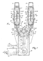
- the protection members 41 realize a protection provided around the circumference of a teat cup.
- the protection member protects the teat cups and promotes the continuous connection of the teat cups to the teats. In the present embodiment, this protection member extends through the overall circumference around two teat cups.
- the protection member is in the shape of a box. Towards the box-like protection members 41 there are provided at some distance from the bottom two strips 50 which extend in the longitudinal direction of the protection member. Carriers 51 are movable along these strips 50 in the longitudinal direction of the protection members 41.
- Respective teat cups 42 and 43 are disposed on each carrier 51 with the aid of a pressure spring 52.
- the teat cups 42 and 43 can freely perform any possible tilting motions on the relevant carrier 51.
- the carriers 51 in a protection member 41 can be moved independently of each other in the longitudinal direction of the protection member by means of a motor-driven threaded spindle 53.
- two third motors 54 are connected to each protection member 41.
- these third motors 54 are all designed as stepper motors.
- the milk and pulsation pipelines 55 and 56, respectively, leading from the teat cups 42 and 43 inside the protection member 41 are forthat purpose passed via apertures made in the second robot arm portion 28 through this second robot arm portion and thereafter through the first robot arm portion 27.
- each of the protection members 41 is provided with a protective rim 57, which is made of a resilient material.
- this rim 57 nevertheless has a protective function.
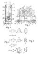
- Figures 6, 7 and 8 show a number of diagrams which illustrate the various motions of the teat cups 42 and 43.
- Figure 6 schematically shows the relative position of the teat cups 42 and 43 in a predominantly horizontal plane. It is illustrated how, starting from a reference position as indicated in the upper diagram in Figure 6, by a lateral motion of the protection members by means of the first and second motors 38 and 44 and by moving the teat cups 42 and 43 up to each other with the aid of the third motors 43, the situations shown in the remaining diagrams of Figure 6 can be obtained, wherein by a pivotal motion about the shaft 40 by means of the third motors 54, if necessary combined with a lateral motion, a position of the individual teat cups is obtained, in which the spacing between the teat cups 42 and the spacing between the teat cups 43 differ.
- the aforesaid eight motors i.e. the two first motors 38, the two second motors 44 and the four third motors 54 provide that the teat cups can assume any possible positions necessary for connection of the cups to the teats of an animal to be milked.
- Figure 7 shows a number of diagrams which illustrate the free pivotability of a protection member 41 about the shaft members 48.
- Figure 8 shows diagrams which illustrate the free pivotability of the supporting elements 36 in conjunction with the protection members 41 about the shaft 32. Because of the fact that the teat cups 42 and 43 can pivot freely relative to the shafts 32 and 48, an optimal adaptation of the position of the teat cups to the specific shape of the udder of a cow can be obtained.
- Figure 3 furthermore shows a detector, more specifically a laser detector 58, which is rigidly fastened on the second robot arm portion 28.
- a detector more specifically a laser detector 58, which is rigidly fastened on the second robot arm portion 28.
- the robot arm has been roughly positioned under the udder of a cow, the position of the teats is determined with the aid of the detector 58, whereafter the positional information supplied by the detector 58 is applied to the computer system 13, with the aid of which the control signals for the motors 38, 44 and 54 are obtained.
- the robot arm construction 26 can be moved upwards.
- the teat cups can be connected substantially simultaneously, whilst because of the fact that the cups can freely tilt about the shafts 32 and 48 an adaptation to the teats of the animal is obtained.
- This adaptation is still further increased by the manner in which the teat cups 42 and 43 are accommodated in the holder 41 by means of pressure springs 52.
Landscapes
- Life Sciences & Earth Sciences (AREA)
- Animal Husbandry (AREA)
- Environmental Sciences (AREA)
- Toys (AREA)
- Manipulator (AREA)
- Housing For Livestock And Birds (AREA)
- External Artificial Organs (AREA)
Applications Claiming Priority (3)
| Application Number | Priority Date | Filing Date | Title |
|---|---|---|---|
| NL9200639 | 1992-04-06 | ||
| NL9200639A NL9200639A (nl) | 1992-04-06 | 1992-04-06 | Inrichting voor het automatisch melken van dieren. |
| EP19930200982 EP0565189B1 (en) | 1992-04-06 | 1993-04-02 | A construction for automatically milking animals |
Related Parent Applications (1)
| Application Number | Title | Priority Date | Filing Date |
|---|---|---|---|
| EP19930200982 Division EP0565189B1 (en) | 1992-04-06 | 1993-04-02 | A construction for automatically milking animals |
Publications (3)
| Publication Number | Publication Date |
|---|---|
| EP0842600A1 EP0842600A1 (en) | 1998-05-20 |
| EP0842600B1 EP0842600B1 (en) | 2002-07-17 |
| EP0842600B2 true EP0842600B2 (en) | 2005-06-01 |
Family
ID=19860667
Family Applications (2)
| Application Number | Title | Priority Date | Filing Date |
|---|---|---|---|
| EP97203714A Expired - Lifetime EP0842600B2 (en) | 1992-04-06 | 1993-04-02 | A construction for automatically milking animals |
| EP19930200982 Expired - Lifetime EP0565189B1 (en) | 1992-04-06 | 1993-04-02 | A construction for automatically milking animals |
Family Applications After (1)
| Application Number | Title | Priority Date | Filing Date |
|---|---|---|---|
| EP19930200982 Expired - Lifetime EP0565189B1 (en) | 1992-04-06 | 1993-04-02 | A construction for automatically milking animals |
Country Status (4)
| Country | Link |
|---|---|
| EP (2) | EP0842600B2 (da) |
| DE (2) | DE69332124T3 (da) |
| DK (2) | DK0565189T3 (da) |
| NL (1) | NL9200639A (da) |
Families Citing this family (40)
| Publication number | Priority date | Publication date | Assignee | Title |
|---|---|---|---|---|
| NL9400630A (nl) * | 1993-11-26 | 1995-06-16 | Lely Nv C Van Der | Inrichting voor het automatisch melken van dieren. |
| NL9302047A (nl) * | 1993-11-26 | 1995-06-16 | Lely Nv C Van Der | Inrichting voor het automatisch melken van dieren. |
| NL9400471A (nl) * | 1994-03-25 | 1995-11-01 | Maasland Nv | Constructie met een inrichting voor het melken van dieren. |
| NL9400472A (nl) * | 1994-03-25 | 1995-11-01 | Maasland Nv | Constructie met een inrichting voor het melken van dieren. |
| DE69535110T2 (de) * | 1994-03-25 | 2007-02-08 | Maasland N.V. | Anlage mit mindestens einer Vorrichtung zum automatischen Melken von Tieren |
| NL9401113A (nl) * | 1994-07-04 | 1996-02-01 | Maasland Nv | Constructie met een inrichting voor het automatisch melken van dieren. |
| NL9500364A (nl) * | 1995-02-24 | 1996-10-01 | Maasland Nv | Inrichting voor het melken van dieren. |
| NL1000010C2 (nl) * | 1995-04-03 | 1996-10-04 | Maasland Nv | Werkwijze voor het positioneren van voor het automatisch melken benodigde middelen onder de uier van een dier, alsmede inrichting waarin deze werkwijze kan worden toegepast. |
| NL1001645C2 (nl) † | 1995-11-14 | 1997-05-21 | Maasland Nv | Constructie met een inrichting voor het melken van dieren. |
| NL1006175C2 (nl) * | 1997-05-30 | 1998-12-01 | Maasland Nv | Inrichting voor het melken van dieren. |
| SE9802557L (sv) * | 1998-07-16 | 1999-07-26 | Alfa Laval Agri Ab | Anordning som är inrättad att uppbära en uppsättning spenkoppar |
| SE517285C2 (sv) * | 1998-07-24 | 2002-05-21 | Delaval Holding Ab | Anordning för automatisk mjölkning av ett djur |
| SE517702C2 (sv) * | 1998-09-04 | 2002-07-09 | Delaval Holding Ab | Metod och anordning för att manövrera spenkoppar för mjölkning av mjölkdjur |
| SE9903112L (sv) † | 1999-09-03 | 2001-03-04 | Delaval Holding Ab | Grafiskt användargränssnitt och förfarande relaterat därtill |
| GB0318733D0 (en) | 2003-08-11 | 2003-09-10 | Icerobotics Ltd | Improvements in or relating to milking machines |
| CA3034793C (en) | 2006-03-15 | 2023-01-03 | Gea Farm Technologies Gmbh | Time of flight teat location system |
| EP2369911B1 (en) | 2008-11-26 | 2016-01-06 | DeLaval Holding AB | Handling of teat cups |
| US9161511B2 (en) | 2010-07-06 | 2015-10-20 | Technologies Holdings Corp. | Automated rotary milking system |
| US9149018B2 (en) | 2010-08-31 | 2015-10-06 | Technologies Holdings Corp. | System and method for determining whether to operate a robot in conjunction with a rotary milking platform based on detection of a milking claw |
| US8720382B2 (en) | 2010-08-31 | 2014-05-13 | Technologies Holdings Corp. | Vision system for facilitating the automated application of disinfectant to the teats of dairy livestock |
| US10111401B2 (en) | 2010-08-31 | 2018-10-30 | Technologies Holdings Corp. | System and method for determining whether to operate a robot in conjunction with a rotary parlor |
| US8800487B2 (en) | 2010-08-31 | 2014-08-12 | Technologies Holdings Corp. | System and method for controlling the position of a robot carriage based on the position of a milking stall of an adjacent rotary milking platform |
| US9049843B2 (en) | 2011-04-28 | 2015-06-09 | Technologies Holdings Corp. | Milking box with a robotic attacher having a three-dimensional range of motion |
| US10357015B2 (en) | 2011-04-28 | 2019-07-23 | Technologies Holdings Corp. | Robotic arm with double grabber and method of operation |
| US9357744B2 (en) | 2011-04-28 | 2016-06-07 | Technologies Holdings Corp. | Cleaning system for a milking box stall |
| US10127446B2 (en) | 2011-04-28 | 2018-11-13 | Technologies Holdings Corp. | System and method for filtering data captured by a 2D camera |
| US9107379B2 (en) | 2011-04-28 | 2015-08-18 | Technologies Holdings Corp. | Arrangement of milking box stalls |
| US8671885B2 (en) | 2011-04-28 | 2014-03-18 | Technologies Holdings Corp. | Vision system for robotic attacher |
| US9215861B2 (en) | 2011-04-28 | 2015-12-22 | Technologies Holdings Corp. | Milking box with robotic attacher and backplane for tracking movements of a dairy animal |
| US9258975B2 (en) | 2011-04-28 | 2016-02-16 | Technologies Holdings Corp. | Milking box with robotic attacher and vision system |
| US9043988B2 (en) | 2011-04-28 | 2015-06-02 | Technologies Holdings Corp. | Milking box with storage area for teat cups |
| US9161512B2 (en) | 2011-04-28 | 2015-10-20 | Technologies Holdings Corp. | Milking box with robotic attacher comprising an arm that pivots, rotates, and grips |
| US8746176B2 (en) | 2011-04-28 | 2014-06-10 | Technologies Holdings Corp. | System and method of attaching a cup to a dairy animal according to a sequence |
| US8885891B2 (en) | 2011-04-28 | 2014-11-11 | Technologies Holdings Corp. | System and method for analyzing data captured by a three-dimensional camera |
| US8683946B2 (en) | 2011-04-28 | 2014-04-01 | Technologies Holdings Corp. | System and method of attaching cups to a dairy animal |
| US9058657B2 (en) | 2011-04-28 | 2015-06-16 | Technologies Holdings Corp. | System and method for filtering data captured by a 3D camera |
| US9107378B2 (en) | 2011-04-28 | 2015-08-18 | Technologies Holdings Corp. | Milking box with robotic attacher |
| US9681634B2 (en) | 2011-04-28 | 2017-06-20 | Technologies Holdings Corp. | System and method to determine a teat position using edge detection in rear images of a livestock from two cameras |
| US8903129B2 (en) | 2011-04-28 | 2014-12-02 | Technologies Holdings Corp. | System and method for filtering data captured by a 2D camera |
| US9265227B2 (en) | 2011-04-28 | 2016-02-23 | Technologies Holdings Corp. | System and method for improved attachment of a cup to a dairy animal |
Family Cites Families (11)
| Publication number | Priority date | Publication date | Assignee | Title |
|---|---|---|---|---|
| US4010714A (en) * | 1974-03-08 | 1977-03-08 | Director, National Institute Of Animal Industry | System for managing milking-cows in stanchion stool |
| NL8304498A (nl) * | 1983-12-30 | 1985-07-16 | Ir Roelof Geert Middel En Rink | Inrichting voor het melken van vee en werkwijze voor het bedrijven van een dergelijke inrichting. |
| ATE74254T1 (de) * | 1985-01-16 | 1992-04-15 | Lely Nv C Van Der | Geraet und verfahren zum melken von tieren, wie z.b kuehen. |
| ATE48737T1 (de) * | 1985-03-12 | 1990-01-15 | Lely Nv C Van Der | Geraet zum melken von tieren. |
| NL8501884A (nl) * | 1985-07-01 | 1987-02-02 | Lely Nv C Van Der | Inrichting voor het melken van dieren. |
| NL8503580A (nl) * | 1985-12-27 | 1987-07-16 | Multinorm Bv | Systeem voor het besturen van een orgaan voor het volgen van een bewegend object. |
| NL193715C (nl) * | 1987-07-23 | 2000-08-04 | Lely Nv C Van Der | Inrichting voor het melken van een dier. |
| NL8701848A (nl) * | 1987-08-05 | 1989-03-01 | Gascoigne Melotte Bv | Melkinrichting. |
| US4941433A (en) * | 1988-05-23 | 1990-07-17 | Agri-Automation Company, Ltd. | Milking method and related apparatus |
| NL8802332A (nl) * | 1988-09-21 | 1990-04-17 | Lely Nv C Van Der | Inrichting voor het melken van een dier. |
| GB8900084D0 (en) * | 1989-01-04 | 1989-03-01 | British Res Agricult Eng | Milking |
-
1992
- 1992-04-06 NL NL9200639A patent/NL9200639A/nl not_active Application Discontinuation
-
1993
- 1993-04-02 DE DE1993632124 patent/DE69332124T3/de not_active Expired - Fee Related
- 1993-04-02 DK DK93200982T patent/DK0565189T3/da active
- 1993-04-02 DE DE1993619167 patent/DE69319167T2/de not_active Expired - Fee Related
- 1993-04-02 EP EP97203714A patent/EP0842600B2/en not_active Expired - Lifetime
- 1993-04-02 EP EP19930200982 patent/EP0565189B1/en not_active Expired - Lifetime
- 1993-04-02 DK DK97203714T patent/DK0842600T4/da active
Also Published As
| Publication number | Publication date |
|---|---|
| DK0565189T3 (da) | 1999-03-01 |
| DE69332124T2 (de) | 2003-03-13 |
| DE69332124T3 (de) | 2006-02-09 |
| DE69319167D1 (de) | 1998-07-23 |
| EP0565189B1 (en) | 1998-06-17 |
| EP0842600A1 (en) | 1998-05-20 |
| DE69332124D1 (de) | 2002-08-22 |
| EP0565189A3 (en) | 1993-12-15 |
| DK0842600T3 (da) | 2002-11-04 |
| NL9200639A (nl) | 1993-11-01 |
| EP0565189A2 (en) | 1993-10-13 |
| EP0842600B1 (en) | 2002-07-17 |
| DE69319167T2 (de) | 1999-01-07 |
| DK0842600T4 (da) | 2005-09-19 |
Similar Documents
| Publication | Publication Date | Title |
|---|---|---|
| EP0842600B2 (en) | A construction for automatically milking animals | |
| EP1120034B1 (en) | A construction including an implement for automatically milking animals | |
| EP1279327B1 (en) | An implement for automatically milking animals | |
| EP0880889B1 (en) | An implement for milking animals | |
| EP0229682B1 (en) | A method of and an implement for milking an animal | |
| EP0194729B1 (en) | Implement for milking animals | |
| EP0480541B1 (en) | A method of automatically milking animals and an implement for performing same | |
| EP0551957B1 (en) | An implement for milking animals | |
| EP0700245B1 (en) | A construction including an implement for milking animals | |
| EP0716567B1 (en) | A construction including an implement for automatically milking animals | |
| EP0880888B1 (en) | An implement for automatically milking animals | |
| EP0647391B1 (en) | A construction for automatically milking animals | |
| EP1042952A2 (en) | A construction for automatically milking animals | |
| US6481372B2 (en) | Construction for automatically milking animals | |
| EP0638232B2 (en) | A construction for automatically milking animals | |
| EP0673596B1 (en) | A construction including an implement for milking animals | |
| EP1169913B1 (en) | An implement for automatically milking animals |
Legal Events
| Date | Code | Title | Description |
|---|---|---|---|
| PUAI | Public reference made under article 153(3) epc to a published international application that has entered the european phase |
Free format text: ORIGINAL CODE: 0009012 |
|
| AC | Divisional application: reference to earlier application |
Ref document number: 565189 Country of ref document: EP |
|
| AK | Designated contracting states |
Kind code of ref document: A1 Designated state(s): DE DK FR GB NL SE |
|
| 17P | Request for examination filed |
Effective date: 19981102 |
|
| 17Q | First examination report despatched |
Effective date: 20000113 |
|
| GRAG | Despatch of communication of intention to grant |
Free format text: ORIGINAL CODE: EPIDOS AGRA |
|
| GRAG | Despatch of communication of intention to grant |
Free format text: ORIGINAL CODE: EPIDOS AGRA |
|
| GRAH | Despatch of communication of intention to grant a patent |
Free format text: ORIGINAL CODE: EPIDOS IGRA |
|
| GRAH | Despatch of communication of intention to grant a patent |
Free format text: ORIGINAL CODE: EPIDOS IGRA |
|
| GRAA | (expected) grant |
Free format text: ORIGINAL CODE: 0009210 |
|
| AC | Divisional application: reference to earlier application |
Ref document number: 565189 Country of ref document: EP |
|
| AK | Designated contracting states |
Kind code of ref document: B1 Designated state(s): DE DK FR GB NL SE |
|
| REG | Reference to a national code |
Ref country code: GB Ref legal event code: FG4D |
|
| REF | Corresponds to: |
Ref document number: 69332124 Country of ref document: DE Date of ref document: 20020822 |
|
| ET | Fr: translation filed | ||
| PLBQ | Unpublished change to opponent data |
Free format text: ORIGINAL CODE: EPIDOS OPPO |
|
| PLBI | Opposition filed |
Free format text: ORIGINAL CODE: 0009260 |
|
| PLBF | Reply of patent proprietor to notice(s) of opposition |
Free format text: ORIGINAL CODE: EPIDOS OBSO |
|
| 26 | Opposition filed |
Opponent name: DELAVAL INTERNATIONAL AB Effective date: 20030408 |
|
| NLR1 | Nl: opposition has been filed with the epo |
Opponent name: DELAVAL INTERNATIONAL AB |
|
| PLBB | Reply of patent proprietor to notice(s) of opposition received |
Free format text: ORIGINAL CODE: EPIDOSNOBS3 |
|
| PUAH | Patent maintained in amended form |
Free format text: ORIGINAL CODE: 0009272 |
|
| STAA | Information on the status of an ep patent application or granted ep patent |
Free format text: STATUS: PATENT MAINTAINED AS AMENDED |
|
| 27A | Patent maintained in amended form |
Effective date: 20050601 |
|
| AK | Designated contracting states |
Kind code of ref document: B2 Designated state(s): DE DK FR GB NL SE |
|
| NLR2 | Nl: decision of opposition |
Effective date: 20050601 |
|
| REG | Reference to a national code |
Ref country code: SE Ref legal event code: RPEO |
|
| NLR3 | Nl: receipt of modified translations in the netherlands language after an opposition procedure | ||
| REG | Reference to a national code |
Ref country code: DK Ref legal event code: T4 |
|
| ET3 | Fr: translation filed ** decision concerning opposition | ||
| PGFP | Annual fee paid to national office [announced via postgrant information from national office to epo] |
Ref country code: DK Payment date: 20090428 Year of fee payment: 17 |
|
| PGFP | Annual fee paid to national office [announced via postgrant information from national office to epo] |
Ref country code: SE Payment date: 20090429 Year of fee payment: 17 Ref country code: NL Payment date: 20090423 Year of fee payment: 17 Ref country code: FR Payment date: 20090417 Year of fee payment: 17 Ref country code: DE Payment date: 20090429 Year of fee payment: 17 |
|
| PGFP | Annual fee paid to national office [announced via postgrant information from national office to epo] |
Ref country code: GB Payment date: 20090429 Year of fee payment: 17 |
|
| REG | Reference to a national code |
Ref country code: NL Ref legal event code: V1 Effective date: 20101101 |
|
| EUG | Se: european patent has lapsed | ||
| REG | Reference to a national code |
Ref country code: DK Ref legal event code: EBP |
|
| GBPC | Gb: european patent ceased through non-payment of renewal fee |
Effective date: 20100402 |
|
| REG | Reference to a national code |
Ref country code: FR Ref legal event code: ST Effective date: 20101230 |
|
| PG25 | Lapsed in a contracting state [announced via postgrant information from national office to epo] |
Ref country code: NL Free format text: LAPSE BECAUSE OF NON-PAYMENT OF DUE FEES Effective date: 20101101 |
|
| PG25 | Lapsed in a contracting state [announced via postgrant information from national office to epo] |
Ref country code: DE Free format text: LAPSE BECAUSE OF NON-PAYMENT OF DUE FEES Effective date: 20101103 |
|
| PG25 | Lapsed in a contracting state [announced via postgrant information from national office to epo] |
Ref country code: GB Free format text: LAPSE BECAUSE OF NON-PAYMENT OF DUE FEES Effective date: 20100402 |
|
| PG25 | Lapsed in a contracting state [announced via postgrant information from national office to epo] |
Ref country code: DK Free format text: LAPSE BECAUSE OF NON-PAYMENT OF DUE FEES Effective date: 20100503 |
|
| PG25 | Lapsed in a contracting state [announced via postgrant information from national office to epo] |
Ref country code: FR Free format text: LAPSE BECAUSE OF NON-PAYMENT OF DUE FEES Effective date: 20100430 |
|
| PG25 | Lapsed in a contracting state [announced via postgrant information from national office to epo] |
Ref country code: SE Free format text: LAPSE BECAUSE OF NON-PAYMENT OF DUE FEES Effective date: 20100403 |