EP0842574B1 - Multiplexeur a insertion-extraction - Google Patents
Multiplexeur a insertion-extraction Download PDFInfo
- Publication number
- EP0842574B1 EP0842574B1 EP96926471A EP96926471A EP0842574B1 EP 0842574 B1 EP0842574 B1 EP 0842574B1 EP 96926471 A EP96926471 A EP 96926471A EP 96926471 A EP96926471 A EP 96926471A EP 0842574 B1 EP0842574 B1 EP 0842574B1
- Authority
- EP
- European Patent Office
- Prior art keywords
- fibre
- port
- output
- trunk
- signals
- Prior art date
- Legal status (The legal status is an assumption and is not a legal conclusion. Google has not performed a legal analysis and makes no representation as to the accuracy of the status listed.)
- Expired - Lifetime
Links
Images


Classifications
-
- G—PHYSICS
- G02—OPTICS
- G02B—OPTICAL ELEMENTS, SYSTEMS OR APPARATUS
- G02B6/00—Light guides; Structural details of arrangements comprising light guides and other optical elements, e.g. couplings
- G02B6/24—Coupling light guides
- G02B6/26—Optical coupling means
- G02B6/28—Optical coupling means having data bus means, i.e. plural waveguides interconnected and providing an inherently bidirectional system by mixing and splitting signals
- G02B6/293—Optical coupling means having data bus means, i.e. plural waveguides interconnected and providing an inherently bidirectional system by mixing and splitting signals with wavelength selective means
- G02B6/29304—Optical coupling means having data bus means, i.e. plural waveguides interconnected and providing an inherently bidirectional system by mixing and splitting signals with wavelength selective means operating by diffraction, e.g. grating
- G02B6/29316—Light guides comprising a diffractive element, e.g. grating in or on the light guide such that diffracted light is confined in the light guide
- G02B6/29317—Light guides of the optical fibre type
- G02B6/29319—With a cascade of diffractive elements or of diffraction operations
- G02B6/2932—With a cascade of diffractive elements or of diffraction operations comprising a directional router, e.g. directional coupler, circulator
-
- G—PHYSICS
- G02—OPTICS
- G02B—OPTICAL ELEMENTS, SYSTEMS OR APPARATUS
- G02B6/00—Light guides; Structural details of arrangements comprising light guides and other optical elements, e.g. couplings
- G02B6/24—Coupling light guides
- G02B6/26—Optical coupling means
- G02B6/28—Optical coupling means having data bus means, i.e. plural waveguides interconnected and providing an inherently bidirectional system by mixing and splitting signals
- G02B6/293—Optical coupling means having data bus means, i.e. plural waveguides interconnected and providing an inherently bidirectional system by mixing and splitting signals with wavelength selective means
- G02B6/29331—Optical coupling means having data bus means, i.e. plural waveguides interconnected and providing an inherently bidirectional system by mixing and splitting signals with wavelength selective means operating by evanescent wave coupling
- G02B6/29332—Wavelength selective couplers, i.e. based on evanescent coupling between light guides, e.g. fused fibre couplers with transverse coupling between fibres having different propagation constant wavelength dependency
-
- G—PHYSICS
- G02—OPTICS
- G02B—OPTICAL ELEMENTS, SYSTEMS OR APPARATUS
- G02B6/00—Light guides; Structural details of arrangements comprising light guides and other optical elements, e.g. couplings
- G02B6/24—Coupling light guides
- G02B6/26—Optical coupling means
- G02B6/28—Optical coupling means having data bus means, i.e. plural waveguides interconnected and providing an inherently bidirectional system by mixing and splitting signals
- G02B6/293—Optical coupling means having data bus means, i.e. plural waveguides interconnected and providing an inherently bidirectional system by mixing and splitting signals with wavelength selective means
- G02B6/29346—Optical coupling means having data bus means, i.e. plural waveguides interconnected and providing an inherently bidirectional system by mixing and splitting signals with wavelength selective means operating by wave or beam interference
- G02B6/2935—Mach-Zehnder configuration, i.e. comprising separate splitting and combining means
- G02B6/29352—Mach-Zehnder configuration, i.e. comprising separate splitting and combining means in a light guide
- G02B6/29353—Mach-Zehnder configuration, i.e. comprising separate splitting and combining means in a light guide with a wavelength selective element in at least one light guide interferometer arm, e.g. grating, interference filter, resonator
-
- G—PHYSICS
- G02—OPTICS
- G02B—OPTICAL ELEMENTS, SYSTEMS OR APPARATUS
- G02B6/00—Light guides; Structural details of arrangements comprising light guides and other optical elements, e.g. couplings
- G02B6/24—Coupling light guides
- G02B6/26—Optical coupling means
- G02B6/28—Optical coupling means having data bus means, i.e. plural waveguides interconnected and providing an inherently bidirectional system by mixing and splitting signals
- G02B6/293—Optical coupling means having data bus means, i.e. plural waveguides interconnected and providing an inherently bidirectional system by mixing and splitting signals with wavelength selective means
- G02B6/29379—Optical coupling means having data bus means, i.e. plural waveguides interconnected and providing an inherently bidirectional system by mixing and splitting signals with wavelength selective means characterised by the function or use of the complete device
- G02B6/2938—Optical coupling means having data bus means, i.e. plural waveguides interconnected and providing an inherently bidirectional system by mixing and splitting signals with wavelength selective means characterised by the function or use of the complete device for multiplexing or demultiplexing, i.e. combining or separating wavelengths, e.g. 1xN, NxM
- G02B6/29382—Optical coupling means having data bus means, i.e. plural waveguides interconnected and providing an inherently bidirectional system by mixing and splitting signals with wavelength selective means characterised by the function or use of the complete device for multiplexing or demultiplexing, i.e. combining or separating wavelengths, e.g. 1xN, NxM including at least adding or dropping a signal, i.e. passing the majority of signals
- G02B6/29383—Adding and dropping
-
- H—ELECTRICITY
- H04—ELECTRIC COMMUNICATION TECHNIQUE
- H04J—MULTIPLEX COMMUNICATION
- H04J14/00—Optical multiplex systems
- H04J14/02—Wavelength-division multiplex systems
- H04J14/0201—Add-and-drop multiplexing
- H04J14/0202—Arrangements therefor
- H04J14/0213—Groups of channels or wave bands arrangements
-
- H—ELECTRICITY
- H04—ELECTRIC COMMUNICATION TECHNIQUE
- H04J—MULTIPLEX COMMUNICATION
- H04J14/00—Optical multiplex systems
- H04J14/02—Wavelength-division multiplex systems
- H04J14/0201—Add-and-drop multiplexing
- H04J14/0215—Architecture aspects
- H04J14/0217—Multi-degree architectures, e.g. having a connection degree greater than two
-
- G—PHYSICS
- G02—OPTICS
- G02B—OPTICAL ELEMENTS, SYSTEMS OR APPARATUS
- G02B6/00—Light guides; Structural details of arrangements comprising light guides and other optical elements, e.g. couplings
- G02B6/24—Coupling light guides
- G02B6/26—Optical coupling means
- G02B6/28—Optical coupling means having data bus means, i.e. plural waveguides interconnected and providing an inherently bidirectional system by mixing and splitting signals
- G02B6/293—Optical coupling means having data bus means, i.e. plural waveguides interconnected and providing an inherently bidirectional system by mixing and splitting signals with wavelength selective means
- G02B6/29379—Optical coupling means having data bus means, i.e. plural waveguides interconnected and providing an inherently bidirectional system by mixing and splitting signals with wavelength selective means characterised by the function or use of the complete device
- G02B6/29398—Temperature insensitivity
-
- H—ELECTRICITY
- H04—ELECTRIC COMMUNICATION TECHNIQUE
- H04J—MULTIPLEX COMMUNICATION
- H04J14/00—Optical multiplex systems
- H04J14/02—Wavelength-division multiplex systems
- H04J14/0201—Add-and-drop multiplexing
- H04J14/0202—Arrangements therefor
- H04J14/0204—Broadcast and select arrangements, e.g. with an optical splitter at the input before adding or dropping
-
- H—ELECTRICITY
- H04—ELECTRIC COMMUNICATION TECHNIQUE
- H04J—MULTIPLEX COMMUNICATION
- H04J14/00—Optical multiplex systems
- H04J14/02—Wavelength-division multiplex systems
- H04J14/0201—Add-and-drop multiplexing
- H04J14/0202—Arrangements therefor
- H04J14/0206—Express channels arrangements
Definitions
- the present invention relates to an add/drop multiplexer for wavelength division multiplexing.
- the invention is especially directed to use with fibre optic cables, in particular to use as a branching unit adapted for use in a fibre optic network.
- the invention further relates to such fibre optic networks, particularly in the context of submarine cable systems employing fibre optic cables.
- Wavelength division multiplexing termed WDM, (discussed in, for example, Hill, British Telecom Technology Journal 6 (3): 24-31) is a technique of considerable benefit in optimising transmission of signals through fibre optic networks.
- WDM Wavelength division multiplexing
- traffic signals to be sent out by a station are modulated on to a number of carrier signals at different predetermined carrier wavelengths.
- Each predetermined carrier wavelength is allocated according to the identities of the send station and of the intended receive station.
- Predetermined carrier wavelengths will be spaced sufficiently far apart in wavelength that they can be discriminated from each other by components of the fibre optic system, but in many networks will need to be grouped sufficiently closely that all carrier wavelengths can be amplified satisfactorily by the same amplifier in a repeater (or in unrepeatered systems, to be carried long distances without significant loss).
- the carrying capacity of a single fibre is enhanced by WDM - rather than carrying a single signal, the fibre is simultaneously carrying several signals, each of a different wavelength.
- Most such transmission networks have a number of nodes at which one or more branches form away from a main trunk or ring.
- one or more carrier wavelengths are dropped down one fibre of the branch and one or more carrier wavelengths (which may be the same as, or different from, those dropped from the trunk or ring) are added to the trunk or ring from another fibre of the branch.
- the component which performs such a function is an Add/Drop Multiplexer (ADM).
- ADM Add/Drop Multiplexer
- WDM is particularly well adapted to efficient routing of signals between send and receive stations.
- optical components can be used to route signals appropriately by directing them according to the carrier wavelength of the signal.
- This solution is appropriate for use in an integrated device: a basic design for a multiplexer of this type is discussed in Dragone et al in IEEE Photonics Technology Letters 3 (10):896-899, and designs employing arrayed-waveguide gratings are disclosed for an ADM in Okamoto et al in Electronics Letters 31 (9):7234 and for an optical splitter/router in Inoue et al in Electronic Letters 31 (9):726-7.
- a difficulty with such silicon-based components is a lack of flexibility: to perform a specific add-drop function for particular wavelengths, a specific device will need to be fabricated.
- a specific device will need to be fabricated.
- it will be necessary for different nodes to add, drop, or pass different combinations of carrier wavelengths: with integrated components of the type described, it may prove necessary to fabricate different components for each node. This could require a different mask to be prepared for each component, and would as a consequence be likely to be prohibitively expensive for a customized network.
- essentially passive optical components can be used which respond differently to different carrier wavelengths. This enables an essentially passive network to be constructed.
- An example of an appropriate wavelength-sensitive optical component is a fibre Bragg grating.
- Fibre Bragg gratings are discussed in Bennion et al, Electronics Letters, Vol. 22, 341-343, 1986.
- a Bragg grating is a notch reflection filter. Light is transmitted through the grating at all wavelengths apart from those falling within a narrow wavelength band. Light within the band is substantially totally reflected.
- a fibre Bragg grating can be adapted to reflect only one of the carrier wavelengths and allow the others to pass.
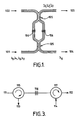
- This ADM is an optical tap comprising a Mach-Zehnder interferometer.
- This optical tap is illustrated in Figure 1. It comprises two input fibres 101,102 and two output fibres 103,104, two 3dB directional couplers 105 which split input light equally between output paths, and two interferometer arms of identical path length linking the couplers.
- each arm there is a Bragg reflection filter 106 which passes light at wavelengths ⁇ 1 , ⁇ 2 , ⁇ 3 , but which reflects light at ⁇ 0 .
- Light at wavelengths ⁇ 1 , ⁇ 2 , ⁇ 3 passes from input 101 through both arms. It then combines constructively at output 103 and is transmitted out through it: however it combines destructively at input 102 (because of the phase shift introduced) and is not transmitted.
- Light at wavelength ⁇ 0 is reflected by both Bragg reflection filters, and in the same manner combines constructively to be transmitted through output 104 but combines destructively at input 101.
- Adjustment means can be provided for this purpose, to compensate for, for example, temperature variation.
- One means of balancing the optical paths is by preparing the device, including writing the gratings onto the fibres, and then exposing one of the arms to uniform UV light to photoinduce an average index change in the fibre core (UV trimming).
- the resulting device is an add/drop multiplexer in the form of a Mach-Zehnder interferometer. This device is shown schematically in Figure 2.
- the Mach-Zehnder interferometer add/drop multiplexer 255 has two inputs, for the trunk input 251 and the branch add fibre 253, and two outputs, for the trunk output 252 and the branch drop fibre 254. There are two "normal paths" - from first input to first output and from second input to second output - which are followed for all signals except for those at carrier wavelength ⁇ 1 , which are rerouted to the other one of the two outputs.
- This device gives a simple and useful add/drop functionality, but is disadvantageous in that two fibres (an add fibre and a drop fibre) are required in the branch for each trunk fibre. This arrangement does require the use of twice as many amplifiers on the spurs as on the main trunk.
- a ring system employing fibre grating filters which reflect at a given one of the wavelengths used in the system is disclosed in Chawki et al, Electronics Letters 31 (6):476-7.
- Each ADM node in the system which is undirectional, comprises a 2 fibre to 1 fibre coupler, a fibre grating filter which reflects at a wavelength ⁇ 1 to be dropped and added at the ADM, but which transmits at other wavelengths used, and a second 2 fibre to 1 fibre coupler.
- At the input side of the first 2 fibre to 1 fibre coupler are the input fibre from the ring and the output fibre to the branch, and at the output side is the fibre grating filter.
- the signal from the ring fibre passes through the coupler to the filter, but the signal at ⁇ 1 , is reflected and passes to the branch through the output fibre.
- the transmitted signal goes to an input of the second 2 fibre to 1 fibre coupler, the other input being connected to an input fibre from the branch so that a new signal at wavelength ⁇ 1 can be added.
- This arrangement does provide an ADM, but a large number of components would be required if such an arrangement was to be employed in a more complex system as a fibre pair is required for each carrier wavelength to be dropped and added.
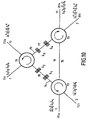
- the whole transmission passes out through the second port of the circulator to grating 116, which reflects the ⁇ 1 component but allows the ⁇ 2 and ⁇ 3 components to pass.
- the ⁇ 1 component thus returns to the second port of the first circulator 115, passes through to the next port in sequence, the third port, and thus passes out along drop branch 113.
- the added signal at carrier wavelength ⁇ 1 from add branch 114 enters the first port of the second circulator 117 and exits through the second port towards grating 116, which reflects it.
- the added ⁇ 1 signal thus joins the ⁇ 2 and ⁇ 3 signals of the main transmission in entering the second port of second circulator 117, and all three carrier wavelengths thus pass out through the third port of the second circulator 117.
- Such an ADM is effective for adding and dropping signals at a given wavelength to a single line, but complex networks would require a large number of such ADMs to be used.
- ADM which can be used in practical communication systems and which has a minimum number of components. It is desired for these components to be highly stable, and for there to be as little need as possible for matching components of the system to each other. In particular, it is desired to provide an ADM which is adapted for use in a practical two-way fibre optic system, with a pair of fibres carrying signals in opposite directions, to allow signals to be added from and dropped to a branch.
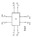
- the invention provides an add/drop multiplexer for use in optical wavelength division multiplexing, the add/drop multiplexer having a first trunk input port for receiving traffic signals from a first part of a first trunk fibre, a second trunk input port for receiving traffic signals from a first part of a second trunk fibre, a first trunk output port for outputting traffic signals to a second part of the first trunk fibre, a second trunk output port for outputting traffic signals to a second part of the second trunk fibre, and a branch input for receiving traffic signals from a branch input fibre, and/or a branch output for outputting traffic signals to a branch output fibre;
- the add/drop multiplexer comprising: means for routing from the first trunk input to the branch output a first set of traffic signals at carrier wavelengths predetermined for transmission of signals from the first trunk fibre to the branch station and for routing from the second trunk input to the branch output a second set of traffic signals at carrier wavelengths predetermined for transmission of signals from the second trunk fibre to the branch station, and means for combining said first and second trunk input port for receiving
- the branch input and branch output may be to and from a common input/output branch fibre.
- the invention may provide an add/drop multiplexer as previously defined for use in an optical wavelength division multiplexing system in which specific carrier wavelengths are assigned for transmission between different stations in the system; said add/drop multiplexer comprising signal splitting means to split the traffic signals input from each of said input ports into signals for provision to selected output ports in accordance with a routing determined by the carrier wavelengths of said traffic signals; signal coupling means for providing output traffic signals at each of said output ports, wherein for each one of said trunk output ports traffic signals from the corresponding trunk input port and from the branch input port at carrier wavelengths selected for routing to that trunk output port are combined for output to that trunk fibre, and wherein for the branch output port traffic signals from the trunk input ports at carrier wavelengths selected for routing to the branch station are combined for output on the branch output fibre.
- the invention also provides a branching unit for use in a fibre optic network comprising an add/drop multiplexer as previously defined.
- the invention further provides a fibre optic network, comprising two terminal stations, two or more trunk fibres for connecting said two terminal stations, one or more branch stations each connected by a spur fibre to a fibre trunk defined by said two or more trunk fibres, and one or more branching units as indicated above on the fibre trunk each to allow exchange of traffic signals between said trunk fibres and one or more of said spur fibres.
- a fibre optic network is adapted such that a substantial part of said fibre trunk comprises submarine cable, and in that said one or more branching units are adapted for submarine use.
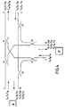
- Figure 4 illustrates a basic coupling scheme used for the first to fourth embodiments of the invention.
- a first fibre optic line enters at first input port 1 and exits through first output port 11.
- a second fibre optic line paired with the first fibre optic line but carrying signals in the opposite direction, enters at second input port 2 and exits at second output port 12.
- the branch point shown is at the end of a chain, so the fibres from first input port 1 and second output port 12 lead to a branch of the system, whereas the fibres from first ioutput port 11 and second input port 2 lead to the next node of the system.
- Signals are dropped to branch output port 13 and are added from branch input port 3. Routing of signals from the input ports to the appropriate output ports is achieved by two sets of components. Firstly, the signal from each input port is split into parts, with a part directed towards the output ports other than the one associated with that input port. This is achieved here by 3dB fibre optic couplers 21, 22, 23. For example, from first input port 1 the signal is transmitted to a first side of the fibre optic coupler 21. There is only one fibre connected to this first side of the coupler. On the second side of the coupler 21, there are two intermediate fibres, one directed to each of the output ports 11, 13 previously indicated. The second step is the combination of the signals in the relevant pair of intermediate fibres to provide the signal for each output port. This is in this case achieved with 3dB fibre optic couplers 31, 32, 33. For example, one intermediate fibre from coupler 23 and another intermediate fibre from coupler 21 are connected to a first side of fibre optic coupler 31.
- coupler 31 At the second side of coupler 31 there is only a single fibre connected to first output port 11, so signals from the first port (via coupler 21) and the branch input port (via coupler 23) are coupled and transmitted out through the first output port 11.
- each station In an arrangement such as that depicted in Figure 4, it is necessary for there to be a unique wavelength for transmissions from each station on the system to every other station: it is not even possible for transmissions between two stations to use the same carrier wavelength for forward and reverse transmissions. In the Figure 4 arrangement, it is thus necessary for each station to be provided with appropriate circuitry for selecting out each carrier wavelength so that the different incoming transmissions can be isolated and detected.
- the first embodiment of the invention shows one way in which the transmission of signals to stations for which the signals are not intended can be prevented.
- Most system elements are as in Figure 4, and are accordingly designated with the same reference numbers: the basic principles of operation are also the same.
- both branch output ports 13 and second output port 12 (as this is at the end of a main trunk) lead to branch stations.
- the main trunk extends from first output port 11 and second input port 2 to another ADM connected to two stations (one along a branch, the other at the end of a trunk), but the system is readily extensible to larger numbers of stations.
- this four station system are thus three carrier wavelengths to be received and sent by each branch station, each for carrying communications from one of the other three stations.
- wavelengths are selected such that the carrier wavelengths to be dropped to a given station are all grouped together in wavelength, so that there is a wavelength range which includes these carrier wavelengths but none of the other carrier wavelengths is use on the system.
- Bandpass filters 41, 42 are then provided before outputs leading to stations to allow only the carrier wavelengths for signals intended for receipt by that station to pass through.
- the branch drop fibre connected to branch output port 13 and the station drop fibre connected to second output port 12 therefore carry only signals intended for receipt by the relevant station.
- This arrangement although substantially secure, is inefficient in its use of wavelengths. It is desirable to keep the number of carrier wavelengths used to a minimum in order both to simplify the range of equipment required and to ensure that even in large systems there is an adequate wavelength spacing between carrier wavelengths.
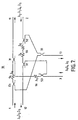
- the second embodiment of the invention is illustrated in Figure 7 and enables a reduction of 50% in the number of wavelengths employed.
- This embodiment resembles the arrangement of Figure 4 in several respects, and the same reference numbers are used to identify components common to both arrangements.
- Figure 6 illustrates a desirable configuration for a fibre optic network appropriate for use with the second and subsequent embodiments of the invention.
- the network has two main terminal stations 20,30 at opposite ends of a fibre trunk.
- the fibre trunk has two fibres carrying signals in opposite directions: fibre 1,11 carries signals from terminal station 20 towards terminal station 30 and fibre 2,12 carries signals from terminal station 30 towards terminal station 20.
- the network also has a third terminal station 40 located on a spur off the fibre trunk. Dropping of signals from the trunk fibres 1,2 to the spur station 40 and adding of signals from the spur station 40 to the trunk fibres 11,12 is achieved by an add/drop multiplexer 10 at a branching station.
- the system may readily be expanded by adding further branching stations each comprising an add/drop multiplexer on the fibre trunk to connect to a spur to a further spur station.
- a significant distinction between the second embodiment of the invention and the Figure 4 arrangement lies in the replacement of the signal splitting fibre optic couplers 21, 22, 23 with paired combinations of fibre optic couplers 51, 52, 53 and notch reflection filters 54, 55, 56.
- the combination of fibre optic coupler and notch reflection filter is used to split the signal input through an input port into two components: one consisting only of carrier wavelengths for a first path, and the other consisting only of carrier wavelengths for a second path.
- this first path is for signals to continue along the trunk, and the second path for signals to be dropped at the branch.
- the first path is for signals to be transmitted in one direction along the trunk, and the second path is for signals to be transmitted in the opposite direction along the trunk.
- the coupler and filter pair of coupler 51 and notch reflection filter 54 is considered.
- Carrier wavelengths ⁇ 1 , ⁇ 2 , ⁇ 3 are input through first input port 1 from a first station: ⁇ 1 carries signals for transmission to the branch station, whereas ⁇ 2 and ⁇ 3 contain signals for transmission to stations further along the main trunk.
- First input port 1 is connected to a first side of fibre optic coupler 51.
- On the second side of fibre optic coupler 51 there is only one intermediate fibre, so the input signal is not split at this point but passes through the coupler to the intermediate fibre.
- the notch reflection filter 54 On the intermediate fibre is the notch reflection filter 54 which reflects ⁇ 1 but which passes ⁇ 2 and ⁇ 3 .
- the ⁇ 2 and ⁇ 3 signals thus pass along the intermediate fibre towards coupler 31 and the first output port 11.
- the ⁇ 1 carrier wavelength signal is however reflected towards the coupler 51.
- This second fibre is an intermediate coupler leading to coupler 33 and hence to the branch output port 13.
- a signal at the ⁇ 1 carrier wavelength after reflection at notch reflection filter 54 thus passes back through coupler 51 to coupler 33 through this intermediate fibre, and hence is dropped through branch output port 13.
- notch reflection filter 54 which reflects ⁇ 1
- two reflection filters could be used, one reflecting ⁇ 2 and the other ⁇ 3 .
- the intermediate fibre with the notch reflection filter would then be connected to coupler 33, and the intermediate fibre connected to the first side of coupler 51 would be connected to coupler 31: the same division of signals would then be achieved.
- the arrangement shown in Figure 7, in which signals along the trunk fibre are not reflected whereas signals for output along the branch fibre are reflected at some point, may however be advantageous in that it would minimize losses along the trunk fibre and ensure that no inappropriate signal reached the branch output port.
- the Figure 7 arrangement allows for a 50% reduction in the number of wavelengths used.
- the carrier wavelength for forward transmission between two stations is also used for return transmission, thus achieving the stated reduction.
- notch reflection filters can be provided in the form of bulk optical components.
- a preferred choice for a notch reflection filter is a fibre Bragg grating.
- This component has been discussed above in relation to the prior art, and manufacture and optimisation of this component is discussed, inter alia, in Bennion et al, Electronics Letters 22 (6):341-3, Dyer et al, Electronics Letters 30 (14):1133-4, Malo et al, Electronics Letters 31 (3):223-5, and Albert et al, Electronics Letters 31 (3):222-3.
- fibre Bragg gratings This enables an all-fibre design for the ADM, with no need to pass any of the signals through a bulk optical component. These components are also not especially lossy - loss is typically in the region of 0.3 dB to 0.5dB.
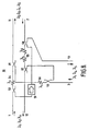
- FIG 7 illustrates a third embodiment of the invention in which the introduction of a optical isolator allows for the removal of one of the fibre optic couplers and thereby significantly reduces the loss of certain carrier wavelengths ( ⁇ 4 , ⁇ 5 in the form of the embodiment illustrated).
- the system of the third embodiment substantially resembles that of the second embodiment, and where the same components are used in both embodiments, the same reference numbers have been used in the figures.
- the distinction between the arrangement shown in Figure 8 and that shown in Figure 7 lies in the mechanism for combining the signals tapped from the trunk fibres for dropping at branch output port 13.
- the ⁇ 1 signal is dropped from the combined signal input at first input port 1 by the combination of fibre optic coupler 51 and notch reflection filter 54 as previously.
- an optical isolator 59 there is now included on the intermediate fibre conveying this tapped signal towards branch output port 13 an optical isolator 59.
- This component which is commercially available from companies such as E-TEK Dynamics, Inc., of 1885 Lundy Avenue, San Jose, CA 95131 USA, allows transmission of light in one direction but not in the other.
- Coupler 58 essentially resembles coupler 52, except in that on the second (notch reflection filter) side of the fibre optic coupler there is as well as the intermediate fibre to coupler 32, an input from the intermediate fibre leading from coupler 51 via isolator 59. On the first side of coupler 58, one of the fibres connected is from second input port 2 and the other leads to branch output port 13. This arrangement is effective for routing the required signals to branch output port 13 without introducing unwanted feedback signals into the system.
- the ⁇ 1 signal originating at first input port 1 passes through fibre optic coupler 58 to branch output 13: any of this signal which is transmitted back out to second input port 2 will not cause difficulties.
- the signals input from second input port 2 it will be possible for these to pass down the intermediate fibre towards coupler 51: however, these signals will not be able to travel past the optical isolator 59.
- the losses involved in the passage through the allowed direction of an optical isolator are significantly less than for passage through a fibre optic coupler, the losses for ⁇ 4 and ⁇ 5 carrier wavelengths are significantly lower than in the Figure 7 arrangement.
- Optical circulators which are referred to in certain of the prior art documents discussed earlier in the specification, are components with at least three ports for which there is a high optical transmissivity for signals entering one port for output from the next port in sequence, with a very high degree of isolation for the same path in the reverse direction.
- Optical circulators can also be obtained from E-TEK Dynamics, Inc, at the aforementioned address. Circulators are significantly less lossy than fibre optic couplers, the loss concerned being of the order of 1dB as compared to 3dB for a fibre optic coupler.
- each of the fibre optic couplers 51, 52, 53 for splitting the input signals has been replaced by a three port optical isolator and each of the fibre optic couplers 31, 32, 33 for combining the appropriate pair of split input signals has been replaced by the combination of a three port optical circulator and a notch reflection filter.
- the replacement of fibre optic couplers 31, 32, 33 by three port optical circulators 61, 62 and 63 is relatively straightforward. For example, for optical circulator 61, the input signal arrives in the same manner as previously from first input port 1.
- Substantially the whole signal passes out through the subsequent port of the optical circulator on to an intermediate fibre, and as before the ⁇ 1 carrier wavelength is reflected by notch reflection filter 54 while the remaining wavelengths pass on in the direction of the first output port 11.
- the reflected ⁇ 1 component returns to the second port of the optical circulator 61 and passes substantially entirely out through the third port for routing towards branch output port 13.
- the replacement of the couplers 31, 32 and 33 for combining the relevant pair of split signals is slightly more complex. For example, the replacement of fibre optic coupler 31 by three port optical circulator 64 and notch reflection filter 67 is considered. Two signals are to be combined, one carrying ⁇ 4 and ⁇ 5 carrier wavelengths from branch input port 3, and one carrying carrier wavelengths ⁇ 2 and ⁇ 3 from first input port 1.
- the signal from branch input port 3 appears along the relevant intermediate fibre from three port optical circulator 63 through notch reflection filter 53. At optical circulator 64, this signal is transmitted substantially wholly out through the next port of the circulator along an intermediate fibre towards optical circulator 61. However, notch reflection filter 67 is provided to reflect both carrier wavelengths ⁇ 4 and ⁇ 5 originating from branch input port 3. This signal from branch input port 3 is therefore reflected back towards the circulator 64, where it passes out through the subsequent circulator port to first output port 11.
- the signal from first input port 1 which has passed through notch reflection filter 54 comprises carrier wavelengths ⁇ 2 and ⁇ 3 . This signal therefore also passes through notch reflection filter 67, and accompanies the signal from branch input port 3 through the circulator 64 and out through first output port 11. As this design employs only notch reflection filters and optical circulators, it has a low loss for all carrier wavelengths.
- the fifth embodiment of the invention is illustrated in Figure 10.
- FIG. 10 there is a first input port 1 and a first output port 11 for the first fibre of the trunk, a second input port 2 and a second output port 12 for the second fibre of the trunk, and also a branch input port 3 and a branch output port 13 for adding and dropping signals from the branch.
- This design employs four port circulators. These circulators, also obtainable from E-TEK Dynamics, Inc., are similar to the three port circulators previously described in that the signal input to one port is then substantially wholly output through the next port in sequence.
- the system illustrated employs three such four port circulators 71, 72, 73.
- each circulator For each circulator, one port is connected to one of the three input ports, another port is connected to one of the three output ports, and the other two ports are each connected by an intermediate fibre to a different one of the other two circulators.
- the sequence order of ports at each circulator is: input port, connection to first one of other circulators, connection to second one of other circulators, output port.
- the splitting of signals from a given input port so that components at different carrier wavelengths are routed to appropriate output ports is achieved by a combination of circulators as described together with notch reflection filters 74, 75 on the intermediate fibres. This combination of notch reflection filters 74, 75 and circulators 71, 72, 73 is also effective to couple the different sets of carrier wavelengths intended for transmission through appropriate ones of the output ports 11, 12, 13.
- wavelength reuse is achieved not by having the same carrier wavelengths for forward and return communication between a given pair of stations as in the second to fourth embodiments, but rather by dropping a particular carrier wavelength from the trunk to the branch and then adding a new signal at the same carrier wavelength for onward transmission along the same trunk fibre.
- Such an arrangement is more appropriate for use in sending signals to and receiving signals from spur stations: the arrangement for wavelength reuse in earlier embodiments is more appropriate for communication between stations on the main trunk.
- a signal having carrier wavelengths signals ⁇ 1 , ⁇ 2 , ⁇ 3 , ⁇ 4 is admitted to first input port 1. This signal is circulated in full to intermediate branch 74, where the ⁇ 1 and ⁇ 2 components are reflected by notch reflection filter 78.
- the ⁇ 3 and ⁇ 4 components however continue to optical circulator 72 and are circulated for transmission out through first output port 11.
- the ⁇ 1 and ⁇ 2 components are however reflected back to circulator 71 and circulated onwards through to intermediate fibre 75, where they pass through notch reflection filters 77 to circulator 73.
- the ⁇ 1 and ⁇ 2 signals are circulated to branch output port 13 for dropping on the branch output fibre.
- signals ⁇ 1 ', ⁇ 2 ', ⁇ 3 ', ⁇ 4 ' are travelling in the opposite direction along the other trunk fibre and are admitted to the system through second input port 2.
- the ⁇ 1 ' and ⁇ 2 ' components are circulated through circulators 72, 73 and 71 in turn and exit through second output port 12.
- the ⁇ 3 ' and ⁇ 4 ' signals after passing through circulators 72 and 73, are reflected by notch reflection filter 77 and return along intermediate fibre 75 to circulator 73, where they are then circulated to the output branch port 13.
- the signals for onward transmission along the same fibre that is, to pass into first input port and out through the first output port, or to pass in through the second input port and out through the second output port
- the signals to be dropped through branch output port 13 are all reflected by one of the notch reflection filters 77, 78.
- This arrangement serves to ensure that only signals which are designated for reception at the branch station are output through branch output port 13.
- Signals ⁇ 1 ", ⁇ 2 ", ⁇ 3 “ and ⁇ 4 " are admitted through branch input port 3. These signals pass through optical circulator 73 onto intermediate fibre 76, and are then circulated onto intermediate fibre 74 by optical circulator 72. At this point the signal is split. ⁇ 1 " and ⁇ 2 " are reflected by notch reflection filter 78 and are circulated by circulator 72 out through the first output port 11, ⁇ 1 " and ⁇ 2 " thus replacing ⁇ 1 and ⁇ 2 on the first of the trunk fibres. ⁇ 3 “ and ⁇ 4 " however pass through notch reflection filters 78 and are circulated by optical circulator 71 onto intermediate fibre 75. These signals are then reflected by notch reflection filters 77 back to optical circulator 71 and are circulated out to second output port 12. ⁇ 3 " and ⁇ 4 " therefore replace ⁇ 3 ' and ⁇ 4 ' on the second of the trunk fibres.
- Figure 10 can be readily scaled to allow one or more further branches to be connected to the same branching point. Additional branches can also receive dropped signals from the two trunk fibres and to replace these dropped signals with added signals at the same carrier wavelength.
- FIG. 12 An add/drop multiplexer according to a sixth embodiment of the invention is illustrated in Figure 12 and provides the branching arrangement shown in Figure 11.
- Table 1 illustrates the carrier wavelengths input and output at each of these ports. Routing table for a 2 spur branching unit Port Description Wavelengths In Wavelengths Out T1i Trunk fibre 1 (in) ⁇ 1 , ⁇ 2 , ⁇ 3 , ⁇ 4 - T1o Trunk fibre 1 (out) - ⁇ " 1 , ⁇ "' 2 , ⁇ 3 , ⁇ 4 T2i Trunk fibre 2 (in) ⁇ ' 1 , ⁇ ' 2 , ⁇ ' 3 , ⁇ ' 4 - T2o Trunk fibre 2 (out) - ⁇ ' 1 , ⁇ ' 2 , ⁇ " 3 , ⁇ ''' 4 B1i Branch fibre 1 (in) ⁇ " 1 , ⁇ " 3 - B1o Branch fibre 1 (out) - ⁇ 1 , ⁇ ' 3 B2i Branch fibre 2 (in) ⁇ ''' 2 ⁇ ''
- the path for each carrier wavelength can be traced through the system employing the principles indicated with respect to the Figure 10 embodiment.
- This arrangement which is expandable by addition of further four port optical circulators and appropriate notch reflection filters to allow further branches to be connected, has significant common features with the Figure 10 embodiment.
- the port sequence is input port, intermediate fibre connected to one of the other circulators, intermediate fibre connected to another one of the other circulators, output port.
- the circulators and intermediate fibres form a ring arrangement.
- Signals for onward transmission along a given trunk fibre are circulated without a reflection at any of the notch reflection filters, whereas signals to be dropped at one or other of the branch output ports 13, 14 are reflected at one or more notch reflection filters 89, 90, 91, 92.
- Notch reflection filters 89, 90, 91, 92 have the function both of splitting signals input from a given input port and of combining signals from different input ports for transmission through a common output port.
- the branches only exchange signals with the two trunk fibres. It is however quite possible with appropriate choices of filters and wavelengths for signals to pass between branches as well.
- optical components employed are passive. None requires there to be any form of active control of the system, as the add drop multiplexers concerned simply route particular carrier wavelengths input through particular input ports through appropriate output ports according to a predetermined scheme in accordance with the characteristics of the components concerned. This is particularly advantageous in the field of submarine cables, where it is extremely difficult and time consuming to change or repair a component on a laid cable, as the cable is typically on the sea bottom and many miles offshore. For this reason it is also desirable for components for use in this field to be "qualified". In this context this has the meaning that the components used are warranted to remain stable over 25 years of use.
- a signal comprising ⁇ 1 , ⁇ 2 , ⁇ 3 , ⁇ 4 is admitted through first input port 1 and signal ⁇ 1 ', ⁇ 2 ', ⁇ 3 ', ⁇ 4 ' is admitted through second input port 2.
- Signals ⁇ 2 '', ⁇ 3 '' are admitted to the system through branch input port 3.
- switchable gratings 93, 94 in the positions as shown, signal ⁇ 2 is dropped through branch output port 13 and replaced by ⁇ 2 '' in the signal emitted through first output port 11.
- ⁇ 3 ' is dropped from the second fibre signal through branch output port 13 and is replaced by ⁇ 3 '' from branch input port 3 in the signal emitted through second output port 12.
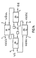
- a fibre optic network as illustrated in Figure 6 is achievable with an add/drop multiplexer as shown in Figure 14.
- This add/drop multiplexer 1 comprises a plurality of interconnected basic multiplexer units 211,212,213,214. Each of these basic multiplexer units has the functionality of the Mach-Zehnder add/drop multiplexer discussed above with relation to Figure 2 - that is, there is a first input and a first output, and a second input and a second output, and routing means are provided such that signals pass from first input to first output and from second input to second output, except at certain predetermined carrier wavelengths, at which signals are routed from first input to second output and from second input to first output.
- the plurality of interconnected basic multiplexer units 211,212,213,214 comprises a ring network.
- the first input and first output are for the first trunk fibre 1,11.
- the first input and first output are for the second trunk fibre 212.
- the second outputs of each of these basic multiplexer units 211,212 lead to the first and second input, respectively, of a third basic multiplexer unit 214.
- this third basic multiplexer unit 214 one of the two outputs is connected to a drop fibre 13 to drop signals to the spur station.
- the other output is connected to an anti-reflection termination 215 to eliminate the possibility of signals passing on to unintended routes.
- each of the first two basic multiplexer units 211,212 are connected to the first and second output, respectively, of a fourth basic multiplexer unit 213.
- this fourth basic multiplexer unit 213 one of the two inputs is connected to an add fibre 3 so that signals can be added from the spur station 40, and the other of the two inputs is connected to an anti-reflection termination 215.
- This arrangement provides the routing indicated in Figure 6. For example, consider signals at ⁇ 2 . Signals at this carrier wavelength are dropped from trunk fibre 1 to spur station 40 at the add/drop multiplexer 10 and replaced on trunk fibre 11 by new signals from the spur station 40 at the same carrier wavelength. However, signals at this carrier wavelength on the other trunk fibre 2 are to pass through add/drop multiplexer 10 and remain on the trunk fibre. The signals at this carrier wavelength entering the add/drop multiplexer from each of the trunk fibres 1,2 and from the add fibre 3 are considered below.
- the signal entering on fibre 1, termed ⁇ 2 enters the add/drop multiplexer at the first input of basic multiplexer unit 211.
- Basic multiplexer unit 211 has notch reflection filters for this wavelength, and is thus adapted to switch signals at this carrier wavelength from the normal path (first input to first output, second input to second output) so that signals are routed to the other output. Accordingly, the ⁇ 2 signal is routed to the second output of basic multiplexer unit 211 and hence to the first input of basic multiplexer unit 214, rather than to the first output of basic multiplexer unit 211 and out back on to trunk fibre 11, as is the case for the remainder of the signals input on trunk fibre 1.
- Basic multiplexer unit 214 has no notch reflection filters for the ⁇ 2 carrier wavelength, and so allows signals at this carrier wavelength to pass through it along the normal path, so the signal passes out through the first output of this basic multiplexer unit and on to branch output fibre 13, from which the signal passes to the spur station 40.
- the signal on fibre 2 at the same carrier wavelength enters add/drop multiplexer 10 at the second input of basic multiplexer unit 212.
- This basic multiplexer unit allows signals at this carrier wavelength to continue along their normal path, so the ⁇ 2 ' signal merely passes out of the second output of basic multiplexer unit 212 and back on to trunk fibre 12.
- the signal from the spur station 40 at this carrier wavelength enters the add/drop multiplexer 10 at the second input of basic multiplexer unit 213.
- This basic multiplexer unit does reroute signals at this carrier wavelength away from the normal path, so the ⁇ 2 " signal passes out through the first output to the second input of basic multiplexer unit 211.
- This basic multiplexer unit also reroutes signals at this carrier wavelength, so the signal passes to the first output of basic multiplexer unit 211 and exits on trunk fibre 11 - the ⁇ 2 " signal has thus replaced the ⁇ 2 signal on the first trunk fibre 11.
- add/drop multiplexers in accordance with this aspect of the invention are that they can be constructed to be very low in loss. This is especially true if Mach-Zehnder add/drop multiplexers are used - these have losses which are typically between 0.5dB and 1dB for each path. There is the further advantage that the losses in such a device are symmetrical. If Mach-Zehnder add/drop multiplexers are employed as basic multiplexer units, the loss in the add/drop multiplexer will typically be of the order of 1dB in the trunk fibres and 2dB in the add to the trunk and in the drop from the trunk.
- the add/drop multiplexer 1 may then be formed as an all-fibre device, containing no active components (not even the magnets and Faraday rotators used in optical isolators and optical circulators). Assembly is also very simple - only four fibre splices are required. The design is as a whole extremely compact, and offers the potential of a very high level of reliability as it is both simple and passive. However, it is quite possible to produce a device in accordance with this aspect of the invention by using basic multiplexer units of the same functionality but with a different construction and with different optical components - this is discussed further below.
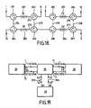
- FIG. 15 shows a further network configuration to which an add/drop multiplexer is adapted.
- this network configuration there is a third trunk fibre 1',11' carrying signals in the same direction as trunk fibre 1,11 and a fourth trunk fibre 2',12' carrying signals in the same direction as trunk fibre 2,12.
- a third trunk fibre 1',11' carrying signals in the same direction as trunk fibre 1,11
- a fourth trunk fibre 2',12' carrying signals in the same direction as trunk fibre 2,12.
- the plurality of interconnected basic multiplexer units comprise a linear network of matched pairs 221,222; 223,224; 225,226; and 227,228, of basic multiplexer units.
- Each basic multiplexer unit of a pair has the same wavelength or wavelengths for rerouting from the normal path - in the case of pair 221,222, this is ⁇ 1 .
- the first input and output of the first basic multiplexer unit 221 of the pair are connected to input fibres and output fibres for a given trunk fibre - in this case, trunk fibre 1,11. Consequently, the only signals rerouted away from trunk fibre 1,11 are at the carrier wavelength ⁇ 1 ; the other signals simply pass straight back out on to the continuation of the same trunk fibre.
- the second input and output of the first basic multiplexer unit 221 of the pair and the first input and output of the second basic multiplexer unit 222 of the pair are connected in a ring.
- the effect of this is that any signal rerouted from the normal path by the first basic multiplexer unit is also rerouted by the second, and vice versa: consequently, signals rerouted from the first input of the first basic multiplexer unit 221 pass to the second output of the second basic multiplexer unit 222 and signals rerouted from the second input of the second basic multiplexer unit 222 pass to the first output of the first basic multiplexer unit 221.
- the same general functionality may be achieved by using a single basic multiplexer unit rather than a matched ring - however, as discussed below, this is not amenable to loss balancing).
- the second output of the second basic multiplexer unit 222 is connected to transmit signals for routing to the drop fibre to the spur station 40. Consequently, the signal at ⁇ 1 dropped from trunk fibre 1 is routed out throught the second output of the second basic multiplexer unit 222 of the pair to be dropped to the spur station 40 on drop fibre 13.
- the second input of the second basic multiplexer unit 222 is connected to receive signals from spur station 40 received in the add/drop multiplexer 10 through add fibre 3.
- Signals at ⁇ 1 from the add fibre 3 are thus received at the second input of the second basic multiplexer unit 222 of the pair, routed through the ring to the first output of the first basic multiplexer unit 221, and pass out on first trunk fibre 11 to replace the signal at ⁇ 1 dropped to the drop fibre 13 through the basic multiplexer unit pair 221,222.
- the connection between matched pairs of basic multiplexer units is achieved by an add/drop line 203 passing from the add fibre 3 to the drop fibre 13 through the second inputs and outputs of the second basic multiplexer units 228,226,224,222 of each of the matched pairs of basic multiplexer units.
- the add/drop line in the embodiment shown originally carries signals at ⁇ 1 , ⁇ 2 , ⁇ 3 and ⁇ 4 from the spur station 40 along add fibre 3.
- signals at ⁇ 4 are dropped to trunk fibre 12' and are replaced by new signals at ⁇ 4 from trunk fibre 2'.
- the add/drop line then carries a combination of signals for adding to trunk fibres (at ⁇ 1 , ⁇ 2 and ⁇ 3 ) and a signal for dropping to the spur station 40 (at ⁇ 4 ) to the next basic multiplexer unit 226.
- the signal at ⁇ 3 is replaced, and after similar transactions at basic multiplexer units 224 and 222 the add/drop line contains only signals for dropping to spur station 40: these are dropped along spur fibre 13.
- Appropriate values of loss are chosen for fixed optical attenuators 231,232,233,234,235,236 so that each path between a trunk fibre and an add or drop fibre has a drop of 5dB.
- the asymmetry of the attenuator values on a single ring is less at the centre than in the end pairs on the chain - this is characteristic of the network design, and becomes more marked if the chain is extended.
- This design is scalable from two wavelengths or trunk fibres (i.e. an arrangement as in Figure 6), to any number of wavelengths. There will be a simple progressive increase in losses for each increase in the number of wavelengths.
- This arrangement is thus particularly well adapted to modular design of fibre optic systems, and also of modular design of individual add/drop multiplexers themselves, thus offering the possibility of simpler device fabrication.
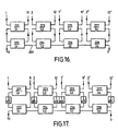
- the Figure 16 add/drop multiplexer and, as indicated previously, the Figure 14 add/drop multiplexer can both be produced using basic multiplexer units which are not Mach-Zehnder add/drop multiplexers, but which have the same functionality.
- a basic multiplexer unit of this functionality but which uses optical circulators in place of a Mach-Zehnder interferometer structure is that shown earlier in Figure 3.
- FIG. 18 shows a two-trunk fibre version of the add/drop multiplexer of Figure 16 adapted to employ such optical circulator basic multiplexer units.
- one matched pair of basic multiplexer units comprises optical circulators 261,262,263,264, notch reflection filters 281,282 and fibres 271,272,273,274. Losses are greater, but the same loss balancing principle as shown in Figure 17 can be employed by appropriate choice of attenuators on fibres 272 and 274 and on equivalent fibres in other matched pairs of basic multiplexer units.
- Figure 19 shows a fibre optic network adapted to utilise a branching unit with an add/drop multiplexer.
- the fibre optic network has a trunk with a first trunk fibre 1,11 and a second trunk fibre 2,12, terminal stations 20 and 30 and a branch station 40, with a branching unit 10 generally as described for, say, Figure 6.
- the add/drop multiplexer 10 also has first and second branching input/outputs 303,304, and the branching unit 10 is adapted both to input one or more branch input signals and output one or more branch output signals at each of these inputs/outputs.
- spur fibres are used for bi-directional transmission, they are not provided with repeaters.
- the relevant signals at given carrier wavelengths also termed channels, can be simply combined and/or separated at branch station 40 by the use of a fibre optic coupler or an optical circulator.
- Use of an optical circulator is advantageous as this involves lower losses.
- Such a configuration allows the use of properties associated with the bi-directional transmission to determine where the channels are routed, and obviates any need for extra fibres.
- FIG. 20 A tenth embodiment of the invention is depicted in Figure 20. This employs a plurality of optical fibre couplers and wavelength routing means.
- the preferred wavelength routing means are notch reflection filters, and in particular fibre Bragg gratings, but alternative components with the same or comparable functionality could also be used.
- the Figure 20 arrangement is adapted for use as branching unit 10 in Figure 19. It comprises six fibre optic couplers 311, 312, 313, 314, 315 and 316 and two fibre Bragg gratings 317, 318.
- first trunk fibre 1,11 an input signal is received at a first left side connection of fibre optic coupler 311 and an output signal is provided at a first right side connection of fibre optic coupler 312.
- second trunk fibre 2,12 an input signal is provided at the second right side connection of coupler 316 and an output signal is provided at a second left side connection of coupler 315.
- a first branching unit bi-directional spur 303 is connected to the left side of coupler 313, and a second bi-directional spur 304 is connected to the right side of coupler 314.
- the couplers are connected in a ring.
- the right side connections of coupler 313 are connected to the free left side connections of couplers 311 and 315 respectively, and the left side connections of coupler 314 are connected to the free right side connections of couplers 312 and 316 respectively.
- the remaining linkages are those provided between the right side of coupler 311 and the left side of coupler 312, and between the right side of coupler 315 and the left side of coupler 316.
- These connections are each achieved by means of fibres having therein one or more fibre Bragg gratings. On the fibre between couplers 311 and 312 there is fibre Bragg grating 317, and on the fibre between couplers 315 and 316 there is fibre Bragg grating 318.
- optical isolators This design can be modified by inclusion of optical isolators to enable different wavelengths to be added or dropped from different fibres: the optical isolators serve to reduce crosstalk to acceptable levels.
- optical circulators and fibre Bragg gratings By using optical circulators and fibre Bragg gratings the restriction of dropping only the same wavelength can be lifted.
- the same or different wavelengths can be used for adding and dropping signals for the different fibres.
- Figure 21 shows an arrangement using three-port optical circulators. Again, the arrangement of Figure 21 is adapted to provide a branching unit 10 for the topology of Figure 19.
- the input signals, output signals, branch input signals and branch output signals effectively comprise two sets, each set comprising one input signal, one output signal, one branch input signal and one branch output signal, in such a way that three three-port optical circulators and one wavelength routing means, here a fibre Bragg grating, are provided for each set.
- a first set comprises optical circulators 321, 322 and 323 and fibre Bragg grating 324.
- the first three-port optical circulator is adapted to receive at its first port signals from the second "set", communicates through its second port with the second port of the second optical circulator 322 of the set through wavelength routing means 324, and from the third port provides an output signal, in this case for first trunk fibre 11.
- the remaining ports of the second optical circulator 322 are connected such that the first port receives an input signal, in this case again from the first trunk fibre 1, and the third port connects to the first port of the third optical circulator 323 of the set.
- the second port of optical circulator 323 is connected to spur fibre 303 and the third port of optical circulator 323 is adapted to provide signals to the circulators of the other set.
- signals input on along the first trunk fibre 1 all pass through circulator 322 to fibre Bragg grating 324.
- Signals at all wavelengths other than ⁇ 2 pass straight through grating 324 and circulator 321 out along first trunk fibre 11.
- Signals at ⁇ 2 are reflected at grating 324 and passed back through circulator 322 to circulator 323 and then out onto spur fibre 303.
- Signals arriving from spur fibre 303 are circulated out through circulator 323 and into the first circulator, circulator 325, of the second set.
- signals from the spur fibre 304 of the other set appear (via circulator 327) at the first port of optical circulator 321.
- Figure 22 shows a modified version of this arrangement which reduces the number of components by replacing one pair of three-port optical circulators with a four-port optical circulator, with a consequent rearrangement in the connections provided.
- Achieving the Figure 19 arrangement thus requires a first and a second four-port circulator, a first and a second three-port circulator and a first and a second wavelength routing means.
- Each of the four-port circulators is connected at one port to a trunk input or output, at another port to a branch input/output, at another port to one of the three-port circulators, and through the other port to the other four-port circulator through wavelength routing means 335.
- the first trunk input passes into first four-port circulator 331 at the first port
- the second port of circulator 331 communicates with second four-port circulator 332 through wavelength routing means 335, which here is a Bragg reflection filter centered at ⁇ 2
- the third port of circulator 331 connects with first branch input/output 303
- the fourth port of circulator 331 connects with the first port of a first three-port circulator 333.
- the connections to the second four-port circulator 332 are effectively in reverse: the first port is connected to the third port of the second three-port circulator 334, the second port is connected to the other branch input/output 304, the third port is connected to the other four-port circulator 331 through wavelength routing means 335, and the final port provides the signal for the first fibre output.
- the two three-port circulators 333 and 334 are connected to each other, through their second ports, by the other wavelength routing means 336, which is here a fibre Bragg grating reflecting at ⁇ 3 .
- the first circulator of this type is effectively mirrored by the second circulator of this type, the third-port of circulator 333 providing the signal for the second trunk output fibre and the first port of the second three-port circulator 334 receiving the signal from the second trunk input fibre.
- signals at all wavelengths other than ⁇ 2 pass straight through circulator 331, wavelength routing means 335, and circulator 332 to the first trunk fibre output 11. Signals at ⁇ 2 are reflected by wavelength routing means 335 and pass out along the first branch input/output fibre 303.
- signals at wavelengths other than ⁇ 3 pass straight through to the corresponding output fibre 12, whereas signals at ⁇ 3 are reflected by wavelength routing means 336 and re-circulated by circulator 334 to circulator 332, where they then pass out to the second branch input/output fibre 304.
- Signals at ⁇ 3 from first branch input/output fibre 303 are circulated through circulator 331 and circulator 333 to wavelength routing means 336, where they are reflected and re-circulated by circulator 333 to the second trunk fibre output 12 to replace the signal dropped to branch input/output 304.
- the replacement signal from the second branch input/output 304 at ⁇ 2 passes through circulator 332, reflects from wavelength routing means 335 and is circulated again by circulator 332 to pass out along the first trunk fibre output.
- FIG. 23 An even smaller number of components is achieved in the arrangement shown in Figure 23.
- This employs only two optical components for each set of a trunk and branch fibre in achieving a topology of Figure 19.
- One of these optical components is a five-port optical circulator. These can be achieved in practice by using five ports of a six-port circulator such as those available commercially, for example, from JDS Fitel Inc. of Nepean, Ontario, Canada.
- the other component is a wavelength routing means, in this case a fibre Bragg grating.
- first five-port optical circulator 341 there is essentially a symmetric arrangement between the first five-port optical circulator 341 and the second five-port optical circulator 342.
- a trunk input fibre inputs a signal to the first port.
- the second port is connected to the fourth port of the other five-port optical circulator through wavelength routing means 343, 344.
- the third port is connected to a branch input/output fibre 303,304.
- the fifth port is connected to a trunk fibre output.
- the trunk fibre input connected to the first port relates to one trunk fibre, but the trunk fibre output connected to the fifth port relates to the other trunk fibre.
- the functionality of the device is essentially that of the arrangement shown in Figures 21 and 22.
- Signals from the first trunk fibre at wavelengths other than ⁇ 2 pass into the first port of circulator 341, through wavelength routing means 343, and then into the fourth port and out through the fifth port of circulator 342 onto the first trunk fibre output 11.
- Signals at ⁇ 2 are reflected back into the second port of circulator 341 and pass out through the third port onto branch input/output fibre 303.
- These signals at ⁇ 2 are replaced on the first trunk output fibre by signals received from the second branch input/output 304.
- a particular advantage of this arrangement is that losses are balanced if the component losses from port to port are equal.
- the optical circulator has a 1 dB loss per circulation and the wavelength routing means, here a fibre Bragg grating, has a 0.5 dB loss both in reflection and transmission, then the port to port loss of this configuration is 2.5dB.
- FIG. 23 uses a given branch input/output to drop signals from one trunk at one wavelength and to replace signals on the other trunk at a different wavelength. This is in accordance with the drawing indicated “option 1" in Figure 24. However, an alternative routing option is available, in which a given branch input/output is used for dropping and replacing signals to the same fibre - this is shown in "option 2" of Figure 24.
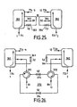
- the option 2 routing can also be achieved with use of a five-port circulator arrangement similar to that shown in Figure 23. Such an arrangement is shown in Figure 25.
- the arrangement differs to that in Figure 23 in that for each circulator, the trunk fibre input and the trunk fibre output connected to the first and fifth ports respectively relate to the same trunk fibre.
- the connection between second and fourth ports is different: instead of the second port of one circulator being connected to the fourth port of the other, the second and fourth ports of the same circulator are connected together with wavelength routing means 353, 354 therebetween. This achieves the routing arrangement of option 2.
- signals at wavelengths other than ⁇ 2 pass out through the second port and are transmitted directly through wavelength routing means 353 to the fourth port, and are circulated out to the first output fibre through the fifth port.
- signals at ⁇ 2 are reflected by wavelength routing means 353 and pass out through the third port onto first branch input/output 303. They are then replaced by signals at the same wavelength from branch input/output 303.
- the replacement signals are circulated out through the fourth port, are reflected by wavelength routing means 353 back to the fourth port, and consequently pass through to the fifth port and out onto the first trunk fibre.
- the arrangement for the second five-port circulator 352 is similar, with signals at ⁇ 3 dropped to second branch input/output 304 and replaced by new added signals at the same wavelength.
- Bi-directional spur arrangements such as those indicated in connection with Figure 19 are appropriate where the length of fibre to the branch station 40 is relatively short, as the performance of the branching unit can then be enhanced without significant degradation of the signals relating to the branch station. It is possible for signals to and from the bi-directional spurs to be separated or combined at the branch station 40 by use of a fibre optic coupler or an optical circulator: use of an optical circulator will generally be preferred as this will reduce losses. However, it is not in all cases appropriate to use such an arrangement, as the distance to the branch station may be too great to allow signals to be transmitted between branch station and branching unit without amplification. In such cases, essentially the same form of branching unit can be employed instead of existing arrangements by addition of an appropriate exchange unit to combine and split signals at the branching unit, rather than at the terminal station. The functionality shown earlier in Figure 6 results.
- the arrangement of Figure 26 differs from that of Figure 25 only in that the third ports are now connected to the exchange unit, rather than to branch inputs/outputs directly.
- the routing of signals not to be exchanged with the branch is unaffected.
- Signals at ⁇ 2 are dropped from the first trunk fibre into the exchange unit 370 from the third port of the first five-port circulator 361.
- the exchange unit 370 comprises two four-port circulators 371, 372 and two wavelength routing means 373, 374, here fibre Bragg gratings at ⁇ 2 and ⁇ 3 .
- the signal at ⁇ 2 received from the first five-port circulator enters the third port of the first four-port circulator 371 of the exchange unit and is circulated to the fourth port.
- This signal passes to second wavelength routing means 374, centered at ⁇ 3 , and thus passes straight through this component to the third port of second four-port circulator 372.
- This signal is circulated to the fourth port, and out to the branch output fibre 13.
- the replacement signal at ⁇ 2 is provided along the branch input fibre 3 to the first port of first four-port circulator 371 of the exchange unit 370.
- the signal is circulated out through the second port and reflected at first wavelength routing means 373, which is centred at ⁇ 2 , back to the first four-port circulator 371 and out through the third port back to the third port of first five-port circulator 361.
- the behaviour for the second trunk fibre is essentially similar in relation to signals at ⁇ 3 .
- bi-directional spurs in branching units of wavelength division multiplexed fibre optic systems can be particularly advantageous to reduce losses and to provide simple systems.
- Particularly simple and convenient systems are provided by the use of five-port optical circulators.
- Bi-directional spur arrangements can be used in conjunction with appropriate hardware within a branch station to split and combine signals as appropriate: alternatively, an exchange unit can be provided within the branching unit to enable the advantageous design of bi-directional spur branching units, particularly those employing five-port circulators, to be modified for use with uni-directional spur fibres carrying either signals from the branch station to the branching unit or signals from the branching unit to the branch station.
Landscapes
- Physics & Mathematics (AREA)
- General Physics & Mathematics (AREA)
- Optics & Photonics (AREA)
- Engineering & Computer Science (AREA)
- Computer Networks & Wireless Communication (AREA)
- Signal Processing (AREA)
- Optical Communication System (AREA)
Claims (20)
- Un multiplexeur à insertion-extraction utilisable dans un multiplexage optique à division de longueurs d'ondes, le multiplexeur à insertion-extraction présentant un premier accès d'entrée d'interconnexion (1) pour recevoir des signaux de trafic provenant d'une première partie d'une première fibre d'interconnexion, un second accès d'entrée d'interconnexion (2) pour recevoir des signaux de trafic provenant d'une première partie d'une seconde fibre d'interconnexion, un premier accès de sortie d'interconnexion (11) pour délivrer des signaux de trafic vers une seconde partie de la première fibre d'interconnexion, un second accès de sortie d'interconnexion (12) pour délivrer des signaux de trafic vers une seconde partie de la seconde fibre d'interconnexion, et un accès d'entrée de branchement (3) pour recevoir des signaux de trafic provenant d'une fibre d'entrée de branchement, et/ou un accès de sortie de branchement (13) pour délivrer des signaux de trafic vers une fibre de sortie de branchement ;
le multiplexeur à insertion-extraction comprenant :des moyens (21, 22) pour acheminer depuis le premier accès d'entrée d'interconnexion (1) vers la sortie de branchement (13) une première série de signaux de trafic (λ4, λ5, λ10) à des longueurs d'ondes porteuses prédéterminées pour une transmission de signaux depuis la première fibre d'interconnexion jusqu'à un poste de branchement (40) et pour acheminer depuis la seconde entrée d'interconnexion (2) vers la sortie de branchement (13) une seconde série de signaux de trafic (λ2,λ5,λ12) à des longueurs d'ondes porteuses prédéterminées pour une transmission de signaux depuis la seconde fibre d'interconnexion jusqu'au poste de branchement (40), et des moyens (33) pour combiner lesdites première et seconde séries de signaux detrafic de manière à sortir au niveau de la sortie de branchement ; et/oudes moyens (23) pour séparer des signaux de trafic (λ1,λ8,λ11) reçus au niveau de l'entrée de branchement (3) en une troisième série de signaux de trafic (λ1,λ8,λ11) à des longueurs d'ondes porteuses prédéterminées pour une transmission de signaux depuis le poste de branchement (40) jusqu'à la première fibre d'interconnexion et une quatrième série de signaux de trafic (λ1,λ8,λ11) à des longueurs d'ondes porteuses prédéterminées pour la transmission de signaux depuis le poste de branchement jusqu'à la seconde fibre d'interconnexion, et des moyens (31) pour acheminer respectivement la première série de signaux de trafic (λ1,λ8,λ11) vers la première sortie d'interconnexion (11) et la quatrième série de signaux de trafic (λ1,λ8,λ11) vers la seconde sortie d'interconnexion (12). - Un multiplexeur à insertion-extraction tel que revendiqué à la revendication 1, dans lequel l'entrée de branchement et la sortie de branchement sont effectuées par rapport à une fibre de branchement entrée/sortie commune.
- Un multiplexeur à insertion-extraction tel que revendiqué à la revendication 2, dans lequel on prévoit deux entrée/sorties de branchement (303, 304), et dans lequel le multiplexeur à insertion-extraction comprend en outre des moyens (316, 318, 314) pour acheminer, depuis la seconde entrée d'interconnexion (2) jusqu'à une seconde entrée/sortie de branchement (304), une troisième série de signaux de trafic (λ3') à des longueurs d'ondes porteuses prédéterminées pour une transmission de signaux depuis ladite seconde fibre d'interconnexion jusqu'au poste de branchement (40), et des moyens pour acheminer, depuis la seconde entrée/sortie de branchement (304) jusqu'à la sortie d'interconnexion (12) d'une seconde parmi les première et seconde fibres d'interconnexion, une quatrième série de signaux de trafic (λ3") à des longueurs d'ondes porteuses prédéterminées pour une transmission de signaux depuis le poste de branchement jusqu'à la seconde parmi lesdites première et seconde sorties d'interconnexion.
- Un multiplexeur à insertion-extraction tel que revendiqué à la revendication 1, utilisable dans un système de multiplexage optique à division de longueurs d'ondes dans lequel des longueurs d'ondes porteuses spécifiques sont attribuées pour une transmission entre différents postes du système, ledit multiplexeur à insertion-extraction comprenant :des moyens diviseurs de signaux (21, 22, 23) pour diviser les signaux de trafic entrant depuis chacun desdits accès d'entrée (1, 2, 3) en signaux prévus pour être fournis à des accès de sortie sélectionnés (11, 12, 13) conformément. à un acheminement déterminé par les longueurs d'ondes porteuses desdits signaux de trafic ;des moyens de couplage de signaux (31, 32, 33) prévus pour fournir des signaux de trafic de sortie à chacun desdits accès de sortie (11, 12, 13), où pour chacun desdits accès de sortie d'interconnexion (11, 12), des signaux de trafic (λ4,λ7,λ10; λ1,λ8,λ11 ou λ1λ2λ3) provenant de l'accès d'entrée d'interconnexion correspondant et de l'accès d'entrée de branchement à des longueurs d'ondes porteuses sélectionnées pour un acheminement à cet accès de sortie d'interconnexion (11, 12) sont combinés pour sortir sur cette fibre d'interconnexion, et où pour l'accès de sortie de branchement, des signaux de trafic (λ4,λ5,λ6) provenant des accès d'entrée d'interconnexion à des longueurs d'ondes porteuses sélectionnées pour un acheminement vers la station de branchement (40) sont combinés pour sortir sur la fibre de sortie de branchement.
- Un multiplexeur à insertion-extraction tel que revendiqué à la revendication 4, dans lequel les moyens de couplage de signaux (31, 32, 33) comprennent un coupleur à fibres optiques pour chaque accès de sortie parmi lesdits accès de sortie (11, 12, 13) afin de coupler les signaux reçus à partir desdits moyens diviseurs de signaux (21, 22, 23) après acheminement vers cet accès de sortie parmi lesdits accès de sortie (11, 12, 13).
- Un multiplexeur à insertion-extraction tel que revendiqué à la revendication 4 ou 5, dans lequel les moyens diviseurs de signaux (21, 22, 23) comprennent un coupleur à fibres optiques pour chaque accès d'entrée parmi les accès d'entrée (1, 2, 3), le coupleur à fibres optiques pour un quelconque accès d'entrée déterminée parmi lesdits accès d'entrée présentant, au niveau d'un premier côté du coupleur, une fibre d'entrée provenant de cet accès d'entrée parmi les accès d'entrée (1, 2, 3) et, au niveau d'un second côté du coupleur, deux fibres de sortie, lesdites deux fibres de sortie étant, dans le cas d'un accès d'entrée d'interconnexion (1, 2), prévues pour acheminer des signaux vers l'accès de sortie d'interconnexion correspondant (11, 12) et vers l'accès de sortie de branchement (13) et, dans le cas de l'accès d'entrée de branchement (3), pour acheminer des signaux vers les premier et second accès de sortie d'interconnexion (11, 12).
- Un multiplexeur à insertion-extraction tel que revendiqué à la revendication 6, dans lequel on prévoit un filtre (41) pour des signaux acheminés vers l'accès de sortie de branchement (13), qui est adapté à transmettre des longueurs d'ondes porteuses (λ4, λ5, λ6) attribuées pour une transmission de signaux vers la fibre de sortie de branchement mais qui n'est pas adapté à transmettre des longueurs d'ondes porteuses non attribuées pour une transmission de signaux vers la fibre de sortie de branchement (13).
- Un multiplexeur à insertion-extraction tel que revendiqué à la revendication 4 ou la revendication 5, dans lequel les moyens diviseurs de signaux comprennent, pour chacun desdits accès d'entrée (1, 2, 3), un composant ou une série de composants présentant un trajet d'entrée pour recevoir des signaux issus de cet accès d'entrée parmi lesdits accès d'entrée (1, 2, 3) et avec de premier et second trajets de sortie pour acheminer des signaux respectivement vers un premier desdits accès de sortie (11, 12, 13) et un second desdits accès de sortie (13, 13, 12), où sur ledit trajet de sortie on trouve un ou plusieurs filtres de réflexion coupe-bande à bande étroite (54) pour réfléchir des signaux aux longueurs d'ondes porteuses attribuées pour une transmission vers ledit second desdits accès de sortie (12) et pour transmettre des signaux à des longueurs d'ondes porteuses attribuées pour une transmission vers ledit premier desdits accès de sortie, et où des signaux à des longueurs d'ondes porteuses attribuées pour une transmission vers ledit second desdits accès de sortie (12) sont acheminés après réflexion au niveau desdits filtres de réflexion coupe-bande à bande étroite sur ledit second trajet de sortie.
- Un multiplexeur à insertion-extraction tel que revendiqué à la revendication 8, dans lequel le composant ou la série de composants comprend un coupleur à fibres optiques (51, 52, 53) dans lequel le trajet d'entrée et le second trajet de sortie sont prévus sur des fibres reliées à un premier côté du coupleur et dans lequel le premier trajet de sortie est prévu sur une fibre reliée à un second côté du coupleur.
- Un multiplexeur à insertion-extraction tel que revendiqué à la revendication 9 lorsqu'elle dépend de la revendication 5, comprenant en outre, dans le second trajet de sortie du coupleur à fibres optiques (51) auquel la première entrée (1) fournit une entrée, un isolateur optique (59) qui permet une transmission de signaux depuis ledit coupleur à fibres optiques, mais qui ne permet pas une transmission de signaux vers ledit coupleur à fibres optiques, où ledit second trajet de sortie fournit une entrée vers le coupleur à fibres optiques (32) pour diviser le signal provenant du second accès d'entrée, le second trajet de sortie provenant du coupleur à fibres optiques (31) pour le premier accès d'entrée étant relié au second côté du coupleur à fibres optiques (58) pour le second accès d'entrée (2), le coupleur à fibres optiques pour le second accès d'entrée (2) servant également ainsi de moyens de couplage de signaux pour l'accès de sortie de branchement (13).
- Un multiplexeur à insertion-extraction tel que revendiqué à la revendication 8 dans lequel ledit composant ou ladite série de composants comprend un circulateur optique (61, 62, 63) pour lequel un premier accès en séquence est relié au trajet d'entrée, un second accès en séquence est relié au premier trajet de sortie; et le troisième accès en séquence est relié au second trajet de sortie.
- Un multiplexeur à insertion-extraction tel que revendiqué à la revendication 11 dans lequel pour chaque accès de sortie parmi les accès de sortie, les moyens de couplage des signaux comprennent un circulateur optique (64, 65, 66), un premier accès en séquence dudit circulateur optique étant prévu pour recevoir des signaux acheminés depuis un premier desdits accès d'entrée (1, 2, 3), un second accès en séquence dudit circulateur optique étant prévu pour recevoir des signaux acheminés depuis un second desdits accès d'entrée (1, 2, 3), et un troisième accès en séquence dudit circulateur optique étant prévu pour fournir des signaux à cet accès de sortie parmi les accès de sortie (11, 12, 13), où un ou plusieurs filtres de réflexion coupe-bande à bande étroite (54, 67, 67, 68) sont prévus sur une fibre reliée au second accès en séquence pour réfléchir des signaux à des longueurs d'ondes porteuses attribuées pour une transmission de signaux depuis ledit premier desdits accès d'entrée vers cet accès de sortie parmi les accès de sortie.
- Un multiplexeur à insertion-extraction tel que revendiqué dans une quelconque des revendications 8 à 12, dans lequel les longueurs d'ondes porteuses attribuées pour une transmission dans le premier accès d'entrée d'interconnexion (1) sont les mêmes longueurs d'ondes porteuses que celles attribuées pour une transmission de signaux hors du second accès de sortie d'interconnexion, les longueurs d'ondes porteuses attribuées pour une transmission vers le second accès d'entrée d'interconnexion (2) sont les mêmes longueurs d'ondes porteuses que celles attribuées pour une transmission hors du premier accès de sortie d'interconnexion, et les longueurs d'ondes porteuses attribuées pour une transmission vers l'accès d'entrée de branchement (3) sont les mêmes longueurs d'ondes porteuses que celles attribuées pour une transmission hors de l'accès de sortie de branchement.
- Un multiplexeur à insertion-extraction tel que revendiqué à la revendication 8, ledit multiplexeur comprenant au moins trois circulateurs optiques à quatre accès (71, 72, 73), où pour chacun desdits circulateurs optiques à quatre accès, le circulateur optique est configuré de telle manière qu'un desdits accès d'entrée (1, 2, 3) est relié à un desdits quatre accès du circulateur, un desdits accès de sortie (11, 12, 13) est relié à un autre desdits quatre accès, et les deux autres accès parmi lesdits quatre accès sont chacun reliés à un circulateur optique différent parmi lesdits circulateurs optiques (71, 72 et 73), et où cet au moins un filtre de réflexion coupe-bande à bande étroite (77, 78) est prévu dans les trajets reliant des paires desdits circulateurs optiques.
- Un multiplexeur à insertion-extraction tel que revendiqué à la revendication 14, dans lequel, pour chacun desdits circulateurs à quatre accès (71, 72, 73), un premier accès en séquence est relié est relié à un desdits accès d'entrée (1, 2, 3), un second accès en séquence est relié à un des autres circulateurs à quatre accès (72, 73, 72), un troisième accès en séquence est relié à un autre parmi les autres circulateurs à quatre accès (73, 71, 71), et un quatrième accès en séquence est relié à un desdits accès de sortie (12, 11, 13).
- Un multiplexeur à insertion-extraction tel que revendiqué à la revendication 14, dans lequel le multiplexeur à insertion-extraction comprend au moins quatre circulateurs optiques à quatre entrées et dans lequel les circulateurs optiques à quatre entrées sont reliés l'un à l'autre dans un anneau, un accès d'entrée de branchement supplémentaire et un accès de sortie de branchement supplémentaire étant prévus pour chaque circulateur optique à quatre accès au-delà du troisième.
- Un multiplexeur à insertion-extraction tel que revendiqué dans une quelconque des revendications 8 à 16, où lesdits filtres de réflexion coupe-bande à bande étroite. sont des réseaux de Bragg à fibres.
- Une unité de branchement utilisable dans un réseau de fibres optiques, unité de branchement qui comprend un premier accès d'entrée d'interconnexion (1) pour recevoir des signaux de trafic provenant d'une première partie d'une première fibre d'interconnexion, un second accès d'interconnexion (2) pour recevoir des signaux de trafic provenant d'une première partie d'une seconde fibre d'interconnexion, un premier accès de sortie d'interconnexion (11) pour délivrer des signaux de trafic vers une seconde partie de la première fibre d'interconnexion, un second accès de sortie d'interconnexion (12) pour délivrer des signaux de trafic vers une seconde partie de la seconde fibre d'interconnexion, et un accès d'entrée de branchement (3) pour recevoir des signaux de trafic provenant d'une fibre d'entrée de branchement, et/ou un accès de sortie de branchement (13) pour délivrer des signaux de trafic vers une fibre de sortie de branchement et comprend un multiplexeur à insertion-extraction tel que revendiqué dans une quelconque revendication précédente.
- Un réseau de fibres optiques, comprenant deux postes terminaux, au moins deux fibres d'interconnexion reliant lesdits deux postes terminaux, au moins un poste de branchement chacun relié par une fibre parasite à une interconnexion de fibres définie par lesdites au moins deux fibres d'interconnexion, et au moins une unité de branchement telle que revendiquée à la revendication 18 sur l'interconnexion de fibres chacune pour permettre un échange de signaux de trafic entre lesdites fibres d'interconnexion et au moins desdites fibres parasites.
- Un réseau de fibres optiques tel que revendiqué à la revendication 19 et adapté pour qu'une partie notable de ladite interconnexion de fibres comprenne un câble sous-marin, et en ce que cette au moins une unité de branchement est adaptée à un usage sous-marin.
Applications Claiming Priority (11)
| Application Number | Priority Date | Filing Date | Title |
|---|---|---|---|
| GBGB9516016.4A GB9516016D0 (en) | 1995-08-04 | 1995-08-04 | A wavelength add/drop multiplexing branching unit |
| GBGB9516014.9A GB9516014D0 (en) | 1995-08-04 | 1995-08-04 | Novel topology for W-ADM using mach-zehnder bragg grating devices |
| GBGB9516018.0A GB9516018D0 (en) | 1995-08-04 | 1995-08-04 | A wavelength add/drop multiplexing branching unit |
| GB9516016 | 1995-08-04 | ||
| GB9516014 | 1995-08-04 | ||
| GB9516018 | 1995-08-04 | ||
| GB9521839 | 1995-10-25 | ||
| GBGB9521839.2A GB9521839D0 (en) | 1995-10-25 | 1995-10-25 | Add/drop multiplexer |
| GBGB9526186.3A GB9526186D0 (en) | 1995-12-21 | 1995-12-21 | Wavelength add/drop multiplexer |
| GB9526186 | 1995-12-21 | ||
| PCT/GB1996/001891 WO1997006614A1 (fr) | 1995-08-04 | 1996-08-02 | Multiplexeur a insertion-extraction |
Publications (2)
| Publication Number | Publication Date |
|---|---|
| EP0842574A1 EP0842574A1 (fr) | 1998-05-20 |
| EP0842574B1 true EP0842574B1 (fr) | 2002-04-03 |
Family
ID=27517302
Family Applications (1)
| Application Number | Title | Priority Date | Filing Date |
|---|---|---|---|
| EP96926471A Expired - Lifetime EP0842574B1 (fr) | 1995-08-04 | 1996-08-02 | Multiplexeur a insertion-extraction |
Country Status (7)
| Country | Link |
|---|---|
| US (2) | US6061484A (fr) |
| EP (1) | EP0842574B1 (fr) |
| JP (1) | JP3865407B2 (fr) |
| CN (1) | CN1195436A (fr) |
| CA (1) | CA2224494A1 (fr) |
| DE (1) | DE69620414T2 (fr) |
| WO (1) | WO1997006614A1 (fr) |
Cited By (2)
| Publication number | Priority date | Publication date | Assignee | Title |
|---|---|---|---|---|
| WO2010132656A1 (fr) | 2009-05-14 | 2010-11-18 | Tyco Electronics Subsea Communications Llc | Configuration de dérivation comprenant un module de dérivation séparé ainsi qu'un module de filtrage de longueur d'onde prédéterminée, et système et procédé correspondants |
| US11664921B2 (en) | 2021-11-04 | 2023-05-30 | Ciena Corporation | Rapid node insertion into or removal from a photonic network |
Families Citing this family (101)
| Publication number | Priority date | Publication date | Assignee | Title |
|---|---|---|---|---|
| SE9403446L (sv) * | 1994-10-11 | 1995-11-27 | Ericsson Telefon Ab L M | Optisk NxN-våglängdskorskopplare |
| CA2225468A1 (fr) * | 1995-08-04 | 1997-02-20 | Alcatel Alsthom Compagnie Generale D'electricite | Acheminement de signaux pour reseaux de fibres optiques |
| DE69620414T2 (de) * | 1995-08-04 | 2002-11-14 | Alcatel, Paris | Optischer einfügungs- und abtrennmultiplexer |
| GB2311429B (en) * | 1995-08-24 | 1998-02-25 | Mitsubishi Electric Corp | Wavelength multiplexed light transfer unit and wavelength multiplexed light transfer system |
| JP3463717B2 (ja) * | 1995-08-24 | 2003-11-05 | 三菱電機株式会社 | 波長多重光伝送装置および波長多重光伝送システム |
| JPH09116490A (ja) * | 1995-10-16 | 1997-05-02 | Fujitsu Ltd | 光多重システム用分岐装置 |
| JP3329655B2 (ja) * | 1996-03-04 | 2002-09-30 | ケイディーディーアイ株式会社 | 光adm装置 |
| US5982518A (en) * | 1996-03-27 | 1999-11-09 | Ciena Corporation | Optical add-drop multiplexers compatible with very dense WDM optical communication systems |
| JPH1032562A (ja) * | 1996-07-16 | 1998-02-03 | Fujitsu Ltd | 光アッド/ドロップ回路 |
| JPH1032546A (ja) * | 1996-07-18 | 1998-02-03 | K D D Kaitei Cable Syst Kk | 光伝送システム及び光分岐装置 |
| JP3055603B2 (ja) * | 1996-07-19 | 2000-06-26 | 日本電気株式会社 | 光ネットワーク |
| CA2267779A1 (fr) * | 1996-10-10 | 1998-04-16 | Tyco Submarine Systems Ltd. | Procede et appareil pour combiner des lignes de signaux optiques a insertion/extraction en provenance de plusieurs unites de derivation |
| KR0183945B1 (ko) * | 1996-11-28 | 1999-05-15 | 삼성전자주식회사 | 광 디멀티플렉서 |
| KR100207602B1 (ko) * | 1996-12-06 | 1999-07-15 | 윤종용 | 광 전력의 손실을 방지하는 광 파장 필터 및 이를 이용한 광 디멀티플렉서 |
| GB2321809A (en) * | 1997-01-31 | 1998-08-05 | Stc Submarine Systems Ltd | Add/drop multiplexer |
| JP3036458B2 (ja) * | 1997-02-28 | 2000-04-24 | 日本電気株式会社 | 光分岐装置および光伝送方法 |
| AU739755B2 (en) * | 1997-06-20 | 2001-10-18 | British Telecommunications Public Limited Company | Multi-band-pass filter |
| US6631018B1 (en) | 1997-08-27 | 2003-10-07 | Nortel Networks Limited | WDM optical network with passive pass-through at each node |
| US6281997B1 (en) | 1997-09-11 | 2001-08-28 | Ciena Corporation | Dense WDM optical multiplexer and demultiplexer |
| US6002503A (en) * | 1997-10-23 | 1999-12-14 | Ciena Corporation | Optical add/drop multiplexer |
| JP3909946B2 (ja) | 1998-01-30 | 2007-04-25 | 富士通株式会社 | 双方向波長スイッチ及び光合分波装置 |
| JP2000010027A (ja) * | 1998-06-18 | 2000-01-14 | Alps Electric Co Ltd | 光スイッチ及びその光スイッチを用いた光通信装置 |
| US7130540B2 (en) | 1998-07-21 | 2006-10-31 | Corvis Corporation | Optical transmission systems, devices, and methods |
| US6449073B1 (en) | 1998-07-21 | 2002-09-10 | Corvis Corporation | Optical communication system |
| US6538783B1 (en) * | 1998-09-18 | 2003-03-25 | Corvis Corporation | Optical systems including add drop devices and methods |
| DE19847410A1 (de) * | 1998-10-14 | 2000-04-20 | Siemens Ag | Optisches unidirektionales Ringnetz |
| US6584102B1 (en) * | 1998-12-21 | 2003-06-24 | At&T Corp. | Communication network apparatus and method |
| US6219474B1 (en) | 1999-03-24 | 2001-04-17 | E-Tek Dynamics | Configurable optical add/drop device |
| GB2348557B (en) | 1999-04-01 | 2002-03-13 | Marconi Comm Ltd | Communications system |
| US6771905B1 (en) | 1999-06-07 | 2004-08-03 | Corvis Corporation | Optical transmission systems including optical switching devices, control apparatuses, and methods |
| US6169626B1 (en) | 1999-06-29 | 2001-01-02 | E-Tek Dynamics | Optical signal interleaver |
| US6275322B1 (en) | 1999-06-08 | 2001-08-14 | Jds Uniphase Corporation | Michelson phase shifter interleaver/deinterleavers |
| US6947670B1 (en) | 1999-06-30 | 2005-09-20 | Lucent Technologies Inc. | Optical add/drop arrangement for ring networks employing wavelength division multiplexing |
| US6275331B1 (en) * | 1999-06-30 | 2001-08-14 | Nortel Networks Limited | Optical amplifiers |
| US6301046B1 (en) | 1999-12-31 | 2001-10-09 | Jds Uniphase Corporation | Interleaver/deinterleavers causing little or no dispersion of optical signals |
| US6335830B1 (en) | 1999-12-31 | 2002-01-01 | Jds Uniphase Corporation | Double-pass folded interleaver/deinterleavers |
| US6337770B1 (en) | 1999-12-31 | 2002-01-08 | Jds Uniphase Corporation | Single-pass folded interleaver/deinterleavers |
| US20010046350A1 (en) * | 2000-02-25 | 2001-11-29 | Tedesco James M. | Configurable Wavelength routing device |
| US6333816B1 (en) | 2000-03-03 | 2001-12-25 | Jds Uniphase Corporation | Apparatus capable of operating as interleaver/deinterleavers or filters |
| JP2001285323A (ja) * | 2000-04-03 | 2001-10-12 | Hitachi Ltd | 光ネットワーク |
| AUPQ617500A0 (en) * | 2000-03-10 | 2000-04-06 | Telstra R & D Management Pty Ltd | A communications network architecture |
| TW510092B (en) * | 2000-05-06 | 2002-11-11 | Browave Corp | High-isolation wavelength management module |
| WO2001097413A1 (fr) * | 2000-06-15 | 2001-12-20 | Agilent Technologies, Inc. | Reflecteur a composants optiques non reciproques |
| KR100366056B1 (ko) * | 2000-08-12 | 2002-12-27 | 한국과학기술원 | 4단자 파장선택 광경로 설정기 및 그를 이용한 양방향 애드/드롭 장치 |
| US7386204B1 (en) | 2000-08-26 | 2008-06-10 | Cidra Corporation | Optical filter having a shaped filter function |
| US6594410B2 (en) | 2000-08-26 | 2003-07-15 | Cidra Corporation | Wide range tunable optical filter |
| US6608709B2 (en) * | 2000-10-03 | 2003-08-19 | Gary Duerksen | Bidirectional WDM optical communication system with bidirectional add-drop multiplexing |
| US6243177B1 (en) * | 2000-10-03 | 2001-06-05 | Seneca Networks, Inc. | Bidirectional WDM optical communication system with bidirectional add-drop multiplexing |
| AUPR054500A0 (en) * | 2000-10-04 | 2000-10-26 | University Of Melbourne, The | Multichannel optical add-drop multiplexer |
| US6288812B1 (en) | 2000-11-03 | 2001-09-11 | Seneca Networks | Bidirectional WDM optical communication network with optical bridge between bidirectional optical waveguides |
| US6339663B1 (en) | 2000-12-22 | 2002-01-15 | Seneca Networks, Inc. | Bidirectional WDM optical communication system with bidirectional optical service channels |
| US6895186B2 (en) | 2000-12-27 | 2005-05-17 | The Trustees Of Columbia University In The City Of New York | System for accessing a wavelength-division-multiplexed bidirectional optical fiber ring network |
| AU2002249965A1 (en) * | 2001-01-22 | 2002-07-30 | Essex Corporation | Optical cdma communications system using otdl device |
| US7062174B2 (en) * | 2001-01-22 | 2006-06-13 | Essex Corporation | Wavelength division multiplexing add-drop multiplexer using an optical tapped delay line |
| US6614569B2 (en) * | 2001-02-12 | 2003-09-02 | Sycamore Networks, Inc. | System and method for narrow channel spaced dense wavelength division multiplexing/demultiplexing |
| US6333798B1 (en) | 2001-02-13 | 2001-12-25 | Seneca Networks, Inc. | Bidirectional WDM optical communication network |
| US20040247239A1 (en) * | 2001-03-12 | 2004-12-09 | Louay Eldada | Hitless errorless trimmable dynamic optical add/drop multiplexer devices |
| EP1378084A1 (fr) * | 2001-04-11 | 2004-01-07 | Lumentis AB | Noeud ajout/retrait de multiplexage par repartition en longueur d'onde (mrl) a faible perte |
| US6973231B2 (en) * | 2001-10-22 | 2005-12-06 | International Optics Communications Corporation | Waveguide grating-based wavelength selective switch actuated by thermal mechanism |
| US20030179998A1 (en) * | 2002-03-22 | 2003-09-25 | Jianjun Zhang | Switchable bragg grating filter |
| US6891989B2 (en) * | 2001-10-22 | 2005-05-10 | Integrated Optics Communications Corporation | Optical switch systems using waveguide grating-based wavelength selective switch modules |
| US6556745B1 (en) * | 2001-11-08 | 2003-04-29 | Intel Corporation | Wavelength selective reflective/transmissive optical coupler and method |
| US20030123798A1 (en) * | 2001-12-10 | 2003-07-03 | Jianjun Zhang | Wavelength-selective optical switch with integrated Bragg gratings |
| US20030108290A1 (en) * | 2001-12-10 | 2003-06-12 | Jianjun Zhang | Optical add/drop devices employing waveguide grating-based wavelength selective switches |
| US6879754B2 (en) * | 2001-12-10 | 2005-04-12 | Integrated Optics Communications Corporation | Drop-before-add optical switching and routing system employing grating-based wavelength selective switches |
| US7184663B2 (en) * | 2002-05-29 | 2007-02-27 | Fujitsu Limited | Optical ring network with hub node and method |
| US7283739B2 (en) * | 2002-05-29 | 2007-10-16 | Fujitsu Limited | Multiple subnets in an optical ring network and method |
| US7283740B2 (en) * | 2002-05-29 | 2007-10-16 | Fujitsu Limited | Optical ring network with optical subnets and method |
| US6922529B2 (en) | 2002-08-09 | 2005-07-26 | Corvis Corporation | Optical communications systems, devices, and methods |
| US6728465B1 (en) | 2002-09-03 | 2004-04-27 | Cisco Technology, Inc. | Semi-reconfigurable subband OADM |
| US7609931B2 (en) * | 2003-04-18 | 2009-10-27 | Enablence, Inc. | Planar waveguide structure with tightly curved waveguides |
| KR100539900B1 (ko) * | 2003-04-19 | 2005-12-28 | 삼성전자주식회사 | 광 스위칭 장치 |
| US20040228574A1 (en) * | 2003-05-14 | 2004-11-18 | Yu Chen | Switchable optical dispersion compensator using Bragg-grating |
| US7321729B2 (en) * | 2003-05-29 | 2008-01-22 | Fujitsu Limited | Optical ring network with selective signal regeneration and wavelength conversion |
| US6928208B2 (en) * | 2003-06-30 | 2005-08-09 | Intel Corporation | Hitless tunable optical add drop multiplexer with vernier gratings |
| US20050018964A1 (en) * | 2003-07-24 | 2005-01-27 | Yu Chen | Compensation of Bragg wavelength shift in a grating assisted direct coupler |
| GB0319965D0 (en) * | 2003-08-27 | 2003-10-01 | Cit Alcatel | Branching unit with full or partial broadcast of wavelengths |
| US7483637B2 (en) * | 2003-11-26 | 2009-01-27 | Fujitsu Limited | Optical ring network with optical subnets and method |
| US20050175346A1 (en) * | 2004-02-10 | 2005-08-11 | Fujitsu Limited | Upgraded flexible open ring optical network and method |
| US20050265720A1 (en) * | 2004-05-28 | 2005-12-01 | Peiching Ling | Wavelength division multiplexing add/drop system employing optical switches and interleavers |
| US20050286896A1 (en) * | 2004-06-29 | 2005-12-29 | Fujitsu Limited | Hybrid optical ring network |
| WO2006051981A1 (fr) * | 2004-11-15 | 2006-05-18 | Hitachi Chemical Company, Ltd. | Reflecteur de lumiere, photocoupleur/filtre de derivation et systeme optique |
| US7120360B2 (en) * | 2005-01-06 | 2006-10-10 | Fujitsu Limited | System and method for protecting traffic in a hubbed optical ring network |
| US7570844B2 (en) * | 2005-01-18 | 2009-08-04 | Doron Handelman | Photonic integrated circuit device and elements thereof |
| KR100689527B1 (ko) | 2005-03-28 | 2007-03-02 | 삼성전자주식회사 | 광 분기/결합 다중화기 |
| US8126329B2 (en) * | 2008-09-03 | 2012-02-28 | Applied Optoelectronics, Inc. | Quad-port optical module with pass-through and add/drop configuration |
| TWI372270B (en) * | 2009-05-04 | 2012-09-11 | Ind Tech Res Inst | Optical switch and communication system of optical signal |
| CN101957476B (zh) * | 2009-07-21 | 2013-01-23 | 华为海洋网络有限公司 | 光分插复用器水下光分路器及其对应的光传输方法和系统 |
| US8401391B2 (en) * | 2009-12-08 | 2013-03-19 | Tyco Electronics Subsea Communications Llc | Channel power management in a branched optical communication system |
| US9641275B2 (en) | 2011-06-17 | 2017-05-02 | Tyco Electronics Subsea Communications Llc | Symmetric optical multiplexing node |
| US8908668B2 (en) * | 2011-09-20 | 2014-12-09 | Avago Technologies General Ip (Singapore) Pte. Ltd. | Device for separating signal transmission and reception and communication system including same |
| US8660391B1 (en) * | 2011-09-30 | 2014-02-25 | Aurrion, Inc. | Heterogeneous waveguide integrated optical isolator and circulator utilizing one or more optical grating couplers |
| US9735914B2 (en) * | 2014-07-25 | 2017-08-15 | Nec Corporation | Mechanism for traffic privacy in reconfigurable add/drop multiplexer based submarine networks |
| WO2016031185A1 (fr) * | 2014-08-26 | 2016-03-03 | 日本電気株式会社 | Appareil de nœud et procédé de commande d'appareil de nœud |
| WO2016051774A1 (fr) * | 2014-10-01 | 2016-04-07 | 日本電気株式会社 | Noeud et procédé de commande de noeud |
| CN108370279B (zh) * | 2015-09-29 | 2020-04-14 | 洛克利光子有限公司 | 光电交换机 |
| GB2549500A (en) * | 2016-04-19 | 2017-10-25 | Airbus Operations Ltd | Node for an optical network |
| CN111295851B (zh) * | 2017-10-30 | 2023-05-12 | 日本电气株式会社 | 海底光学通信系统和海底分支装置 |
| US10337867B1 (en) | 2018-04-13 | 2019-07-02 | Northrop Grumman Systems Corporation | Symmetrical wavelength multiplexor for fiber optic gyro source |
| US11432434B2 (en) | 2020-12-07 | 2022-08-30 | Ciena Corporation | Apparatus and method for modifying airflow of a network element |
| CN113572564B (zh) * | 2021-09-22 | 2021-11-26 | 华海通信技术有限公司 | 一种光分插复用分支器、通信系统及信号传输方法 |
Family Cites Families (6)
| Publication number | Priority date | Publication date | Assignee | Title |
|---|---|---|---|---|
| JPH0357343A (ja) * | 1989-07-26 | 1991-03-12 | Oki Electric Ind Co Ltd | 光交換機 |
| US5526153A (en) * | 1994-01-21 | 1996-06-11 | At&T Corp. | Optical channel adding/dropping filter |
| JP3277970B2 (ja) * | 1994-03-25 | 2002-04-22 | 日本電信電話株式会社 | ループバック光路付アレイ導波路回折格子型光合分波器 |
| FR2718869B1 (fr) * | 1994-04-13 | 1996-05-24 | Andre Hamel | Architecture de réseau en boucle de transmission à accès multiple par routage spectral. |
| DE69620414T2 (de) * | 1995-08-04 | 2002-11-14 | Alcatel, Paris | Optischer einfügungs- und abtrennmultiplexer |
| JP3463717B2 (ja) | 1995-08-24 | 2003-11-05 | 三菱電機株式会社 | 波長多重光伝送装置および波長多重光伝送システム |
-
1996
- 1996-08-02 DE DE69620414T patent/DE69620414T2/de not_active Expired - Lifetime
- 1996-08-02 CN CN96196665A patent/CN1195436A/zh active Pending
- 1996-08-02 JP JP50823097A patent/JP3865407B2/ja not_active Expired - Lifetime
- 1996-08-02 CA CA002224494A patent/CA2224494A1/fr not_active Abandoned
- 1996-08-02 WO PCT/GB1996/001891 patent/WO1997006614A1/fr active IP Right Grant
- 1996-08-02 US US09/000,432 patent/US6061484A/en not_active Expired - Lifetime
- 1996-08-02 EP EP96926471A patent/EP0842574B1/fr not_active Expired - Lifetime
-
2000
- 2000-04-05 US US09/543,341 patent/US6310994B1/en not_active Expired - Lifetime
Cited By (5)
| Publication number | Priority date | Publication date | Assignee | Title |
|---|---|---|---|---|
| WO2010132656A1 (fr) | 2009-05-14 | 2010-11-18 | Tyco Electronics Subsea Communications Llc | Configuration de dérivation comprenant un module de dérivation séparé ainsi qu'un module de filtrage de longueur d'onde prédéterminée, et système et procédé correspondants |
| CN102804648A (zh) * | 2009-05-14 | 2012-11-28 | 泰科电子海底通信有限责任公司 | 包括单独分支单元和预定波长滤波器单元的分支配置以及包括该配置的系统和方法 |
| CN102804648B (zh) * | 2009-05-14 | 2015-12-02 | 泰科电子海底通信有限责任公司 | 包括单独分支单元和预定波长滤波器单元的分支配置以及包括该配置的系统和方法 |
| US10003425B2 (en) | 2009-05-14 | 2018-06-19 | Tyco Electronics Subsea Communications Llc | Branching configuration including separate branching unit and predetermined wavelength filter unit and system and method including the same |
| US11664921B2 (en) | 2021-11-04 | 2023-05-30 | Ciena Corporation | Rapid node insertion into or removal from a photonic network |
Also Published As
| Publication number | Publication date |
|---|---|
| US6061484A (en) | 2000-05-09 |
| CA2224494A1 (fr) | 1997-02-20 |
| EP0842574A1 (fr) | 1998-05-20 |
| DE69620414D1 (de) | 2002-05-08 |
| WO1997006614A1 (fr) | 1997-02-20 |
| JP3865407B2 (ja) | 2007-01-10 |
| US6310994B1 (en) | 2001-10-30 |
| JPH11513207A (ja) | 1999-11-09 |
| CN1195436A (zh) | 1998-10-07 |
| DE69620414T2 (de) | 2002-11-14 |
Similar Documents
| Publication | Publication Date | Title |
|---|---|---|
| EP0842574B1 (fr) | Multiplexeur a insertion-extraction | |
| US6185023B1 (en) | Optical add-drop multiplexers compatible with very dense WDM optical communication systems | |
| US6519064B1 (en) | Scalable add/drop architecture for lightwave communication system | |
| US7184666B1 (en) | Reconfigurable optical add-drop multiplexer | |
| US7136586B2 (en) | Optical communication system | |
| US5774606A (en) | Optical fiber transmission system with a passive optical router | |
| JP2001112034A (ja) | クロス接続交換機及びその実現方法 | |
| KR20030065487A (ko) | 양방향 광분기 결합기를 갖는 양방향 wdm 광 통신 시스템 | |
| JP2000068933A (ja) | 多重波長光波システム用合流/分岐フィルタ | |
| US10256936B2 (en) | Method and apparatus for optical node construction using software programmable ROADMs | |
| US6449072B1 (en) | Add/drop multiplexer | |
| KR20030070892A (ko) | 양방향성 광 도파관들 사이에 광 브리지를 갖는 양방향성파장 분할 다중화 방식의 통신 네트워크 | |
| KR20010075468A (ko) | Wdm-채널 등화기 | |
| US6504970B2 (en) | Planar lightwave wavelength blocker | |
| US6243177B1 (en) | Bidirectional WDM optical communication system with bidirectional add-drop multiplexing | |
| KR20040015057A (ko) | 양방향 wdm 광통신 네트워크 | |
| US6205269B1 (en) | Optical add/drop multiplexer | |
| US6516112B1 (en) | Optical wavelength filter and demultiplexer | |
| EP1151567B1 (fr) | Multiplexeur optique à insertion-extraction | |
| US6552834B2 (en) | Methods and apparatus for preventing deadbands in an optical communication system | |
| US6381049B1 (en) | Multi-port optical multiplexer element | |
| US6288812B1 (en) | Bidirectional WDM optical communication network with optical bridge between bidirectional optical waveguides | |
| JP3149916B2 (ja) | 波長多重光中継増幅装置 | |
| US10574380B2 (en) | Method and apparatus for optical node construction using software programmable ROADMs having N X M wavelength selective switches | |
| CA2404473A1 (fr) | Systeme de commutation optique a equilibrage de puissance |
Legal Events
| Date | Code | Title | Description |
|---|---|---|---|
| PUAI | Public reference made under article 153(3) epc to a published international application that has entered the european phase |
Free format text: ORIGINAL CODE: 0009012 |
|
| 17P | Request for examination filed |
Effective date: 19980204 |
|
| AK | Designated contracting states |
Kind code of ref document: A1 Designated state(s): DE FR GB IT |
|
| RAP3 | Party data changed (applicant data changed or rights of an application transferred) |
Owner name: ALCATEL |
|
| RAP3 | Party data changed (applicant data changed or rights of an application transferred) |
Owner name: ALCATEL |
|
| GRAG | Despatch of communication of intention to grant |
Free format text: ORIGINAL CODE: EPIDOS AGRA |
|
| 17Q | First examination report despatched |
Effective date: 20010726 |
|
| GRAG | Despatch of communication of intention to grant |
Free format text: ORIGINAL CODE: EPIDOS AGRA |
|
| GRAH | Despatch of communication of intention to grant a patent |
Free format text: ORIGINAL CODE: EPIDOS IGRA |
|
| REG | Reference to a national code |
Ref country code: GB Ref legal event code: IF02 |
|
| GRAH | Despatch of communication of intention to grant a patent |
Free format text: ORIGINAL CODE: EPIDOS IGRA |
|
| RBV | Designated contracting states (corrected) |
Designated state(s): DE FR GB IT |
|
| GRAA | (expected) grant |
Free format text: ORIGINAL CODE: 0009210 |
|
| AK | Designated contracting states |
Kind code of ref document: B1 Designated state(s): DE FR GB IT |
|
| REF | Corresponds to: |
Ref document number: 69620414 Country of ref document: DE Date of ref document: 20020508 |
|
| ET | Fr: translation filed | ||
| PLBE | No opposition filed within time limit |
Free format text: ORIGINAL CODE: 0009261 |
|
| STAA | Information on the status of an ep patent application or granted ep patent |
Free format text: STATUS: NO OPPOSITION FILED WITHIN TIME LIMIT |
|
| 26N | No opposition filed |
Effective date: 20030106 |
|
| REG | Reference to a national code |
Ref country code: FR Ref legal event code: CD |
|
| REG | Reference to a national code |
Ref country code: GB Ref legal event code: 732E Free format text: REGISTERED BETWEEN 20131114 AND 20131120 |
|
| REG | Reference to a national code |
Ref country code: FR Ref legal event code: GC Effective date: 20140717 |
|
| REG | Reference to a national code |
Ref country code: FR Ref legal event code: RG Effective date: 20141016 |
|
| REG | Reference to a national code |
Ref country code: FR Ref legal event code: PLFP Year of fee payment: 20 |
|
| PGFP | Annual fee paid to national office [announced via postgrant information from national office to epo] |
Ref country code: DE Payment date: 20150821 Year of fee payment: 20 Ref country code: GB Payment date: 20150819 Year of fee payment: 20 |
|
| PGFP | Annual fee paid to national office [announced via postgrant information from national office to epo] |
Ref country code: FR Payment date: 20150820 Year of fee payment: 20 |
|
| PGFP | Annual fee paid to national office [announced via postgrant information from national office to epo] |
Ref country code: IT Payment date: 20150824 Year of fee payment: 20 |
|
| REG | Reference to a national code |
Ref country code: DE Ref legal event code: R071 Ref document number: 69620414 Country of ref document: DE |
|
| REG | Reference to a national code |
Ref country code: GB Ref legal event code: PE20 Expiry date: 20160801 |
|
| PG25 | Lapsed in a contracting state [announced via postgrant information from national office to epo] |
Ref country code: GB Free format text: LAPSE BECAUSE OF EXPIRATION OF PROTECTION Effective date: 20160801 |