EP0842329B2 - Verfahren zum erzeugen eines pfahles durch schneckenbohren - Google Patents
Verfahren zum erzeugen eines pfahles durch schneckenbohren Download PDFInfo
- Publication number
- EP0842329B2 EP0842329B2 EP96925898A EP96925898A EP0842329B2 EP 0842329 B2 EP0842329 B2 EP 0842329B2 EP 96925898 A EP96925898 A EP 96925898A EP 96925898 A EP96925898 A EP 96925898A EP 0842329 B2 EP0842329 B2 EP 0842329B2
- Authority
- EP
- European Patent Office
- Prior art keywords
- auger
- concrete
- withdrawal
- penetration
- soil
- Prior art date
- Legal status (The legal status is an assumption and is not a legal conclusion. Google has not performed a legal analysis and makes no representation as to the accuracy of the status listed.)
- Expired - Lifetime
Links
- 239000002689 soil Substances 0.000 claims abstract description 81
- 230000035515 penetration Effects 0.000 claims abstract description 39
- 238000000034 method Methods 0.000 claims abstract description 23
- 230000010006 flight Effects 0.000 claims abstract description 14
- 238000010008 shearing Methods 0.000 claims description 3
- 239000004576 sand Substances 0.000 description 9
- 230000000694 effects Effects 0.000 description 8
- 230000008569 process Effects 0.000 description 7
- 230000009471 action Effects 0.000 description 5
- 238000009412 basement excavation Methods 0.000 description 5
- 238000006073 displacement reaction Methods 0.000 description 4
- 230000007246 mechanism Effects 0.000 description 4
- 238000005086 pumping Methods 0.000 description 4
- 230000032258 transport Effects 0.000 description 4
- 238000004458 analytical method Methods 0.000 description 3
- 238000013459 approach Methods 0.000 description 3
- 239000004927 clay Substances 0.000 description 3
- 238000010276 construction Methods 0.000 description 3
- 230000002093 peripheral effect Effects 0.000 description 3
- 230000000630 rising effect Effects 0.000 description 3
- XLYOFNOQVPJJNP-UHFFFAOYSA-N water Substances O XLYOFNOQVPJJNP-UHFFFAOYSA-N 0.000 description 3
- 229910000278 bentonite Inorganic materials 0.000 description 2
- 239000000440 bentonite Substances 0.000 description 2
- SVPXDRXYRYOSEX-UHFFFAOYSA-N bentoquatam Chemical compound O.O=[Si]=O.O=[Al]O[Al]=O SVPXDRXYRYOSEX-UHFFFAOYSA-N 0.000 description 2
- 230000015572 biosynthetic process Effects 0.000 description 2
- 230000001419 dependent effect Effects 0.000 description 2
- 238000000605 extraction Methods 0.000 description 2
- 230000000977 initiatory effect Effects 0.000 description 2
- 238000009434 installation Methods 0.000 description 2
- 239000000463 material Substances 0.000 description 2
- 238000012544 monitoring process Methods 0.000 description 2
- 239000011800 void material Substances 0.000 description 2
- 230000009286 beneficial effect Effects 0.000 description 1
- 238000009530 blood pressure measurement Methods 0.000 description 1
- 230000008859 change Effects 0.000 description 1
- 238000004891 communication Methods 0.000 description 1
- 238000013461 design Methods 0.000 description 1
- 230000001627 detrimental effect Effects 0.000 description 1
- 230000010339 dilation Effects 0.000 description 1
- 230000003292 diminished effect Effects 0.000 description 1
- 238000005553 drilling Methods 0.000 description 1
- 230000008713 feedback mechanism Effects 0.000 description 1
- 239000012530 fluid Substances 0.000 description 1
- 238000002347 injection Methods 0.000 description 1
- 239000007924 injection Substances 0.000 description 1
- 230000033001 locomotion Effects 0.000 description 1
- 238000005259 measurement Methods 0.000 description 1
- 239000002184 metal Substances 0.000 description 1
- 239000000203 mixture Substances 0.000 description 1
- 230000035484 reaction time Effects 0.000 description 1
- 230000002787 reinforcement Effects 0.000 description 1
- 239000000725 suspension Substances 0.000 description 1
Images


Classifications
-
- E—FIXED CONSTRUCTIONS
- E02—HYDRAULIC ENGINEERING; FOUNDATIONS; SOIL SHIFTING
- E02D—FOUNDATIONS; EXCAVATIONS; EMBANKMENTS; UNDERGROUND OR UNDERWATER STRUCTURES
- E02D5/00—Bulkheads, piles, or other structural elements specially adapted to foundation engineering
- E02D5/22—Piles
- E02D5/34—Concrete or concrete-like piles cast in position ; Apparatus for making same
- E02D5/36—Concrete or concrete-like piles cast in position ; Apparatus for making same making without use of mouldpipes or other moulds
-
- E—FIXED CONSTRUCTIONS
- E02—HYDRAULIC ENGINEERING; FOUNDATIONS; SOIL SHIFTING
- E02D—FOUNDATIONS; EXCAVATIONS; EMBANKMENTS; UNDERGROUND OR UNDERWATER STRUCTURES
- E02D15/00—Handling building or like materials for hydraulic engineering or foundations
- E02D15/02—Handling of bulk concrete specially for foundation or hydraulic engineering purposes
- E02D15/04—Placing concrete in mould-pipes, pile tubes, bore-holes or narrow shafts
-
- E—FIXED CONSTRUCTIONS
- E21—EARTH OR ROCK DRILLING; MINING
- E21B—EARTH OR ROCK DRILLING; OBTAINING OIL, GAS, WATER, SOLUBLE OR MELTABLE MATERIALS OR A SLURRY OF MINERALS FROM WELLS
- E21B44/00—Automatic control systems specially adapted for drilling operations, i.e. self-operating systems which function to carry out or modify a drilling operation without intervention of a human operator, e.g. computer-controlled drilling systems; Systems specially adapted for monitoring a plurality of drilling variables or conditions
Definitions
- This invention relates to auger piling, and in particular, but not exclusively, to the automation of the digging and piling phases of continuous flight auger piling operations.
- Continuous flight auger piling has been used in the construction industry since the early 1980s. Piles are constructed by drilling to the required depth with a continuous flight auger mounted on a piling rig, withdrawing the auger, and pumping concrete into the excavation through the auger as the auger is withdrawn. A reinforcement cage may subsequently be placed in the wet concrete.
- Reliable installation of the pile is influenced by a number of factors.
- a first consideration is that the ground surrounding the excavation should not be overly disturbed.
- a second consideration is that sufficient concrete should be delivered through the auger so as to prevent ingress of soil from the walls of the excavation which would otherwise contaminate the concrete cross-section.
- An auger turning in a soil where there is no peripheral friction will not transport soil upwards and will be very inefficient.
- An auger turning in a soil with a high angle of friction (this is where the vertical component of the shear force between soil on an auger flight relative to soil comprising the bore wall is large compared to the horizontal component) will have little lateral pressure available from the soil and will therefore be an inefficient transporter.
- an auger turning in a loose sand for example, is subject to a high lateral soil pressure and will be an efficient transporter. If the penetration rate of the auger in such a soil is not fast enough to keep the auger flights fully loaded from the digging action, the auger will load material by inward failure of the bore wall and cause considerable disturbance to the surrounding ground.
- BE-A-878215 a method of continuous flight auger piling is proposed in which the rate of penetration of the auger is adjusted to achieve an ideal speed which is determined by consideration of the auger geometry.
- the present invention improves the digging efficiency over known systems which rely on trial and error. Furthermore, by reducing the disturbance to the soil comprising the bore wall, the skin friction available for the eventual pile is increased, and the volume of concrete required for piling is reduced, since less concrete escapes into the surrounding soil.
- the auger is driven in such a way that the auger penetrates the ground to a predetermined depth, at which depth the advance of the auger is arrested in order to allow shearing of soil surrounding the bore wall to take place. The auger is then permitted to advance again before penetration is again arrested. This procedure may be repeated until the desired depth is reached.
- the electronic computer means and auger control means are arranged to control the stepwise advance of the auger in order to achieve a specific predetermined number of auger revolutions per metre of penetration. It is possible to achieve very fine control of the auger by this means, enabling thereby almost continuous penetration at the desired rate of advance. In contrast, conventional manual control permits only coarse stepwise advancement of the auger.
- determining the maximum torque available from the auger rig by, for example, measuring the hydraulic pressure in the drive mechanism when the rig is stalled, it is possible to ensure that the auger is not allowed to advance when ground conditions are such that the maximum torque is developed. This helps to prevent the auger from reaching a stage in which it becomes stuck in the ground with no excess torque available to initiate soil shearing.
- the first aspect of the present invention may additionally comprise steps wherein:
- the second aspect of the present invention may additionally comprise means for withdrawing the auger from the ground, means for supplying concrete to the tip of the auger during withdrawal, means for measuring and/or controlling the supply of concrete to the ground, and electronic computer means for controlling the auger during the withdrawal phase of its operation so as to ensure that at least the tip of the auger remains immersed in concrete during withdrawal.
- over-supply is at least 5% and preferably between 10 to 35%, greater than the theoretical minimum.
- the actual value adopted in any instance will be governed principally by ground conditions at the site of operation, as will be appreciated by those skilled in this art. Over-supply of concrete helps to ensure that the excavation is filled to capacity and compensates for minor disturbances introduced into the soil surrounding the bore wall.
- the present invention provides accurate control over the volume of concrete supplied and avoids the wastage which is inherent in the systems of the prior art. It is important to keep the tip of the auger immersed in concrete during the withdrawal phase in order to prevent inward failure of the bore wall leading to the concrete of the resulting pile becoming contaminated with soil.
- the concrete supply is measured by way of an electromagnetic flowmeter, preferred examples of which may provide a resolution of ⁇ 1dm 3 to an absolute accuracy of approximately ⁇ 5%.
- an electromagnetic flowmeter preferred examples of which may provide a resolution of ⁇ 1dm 3 to an absolute accuracy of approximately ⁇ 5%.
- the nature of the aggregate in the concrete gives rise to this degree of variation in the accuracy of measurement.
- the means for withdrawing the auger comprises a hydraulic rig incorporating an electronically-controlled hydraulic valve. This is in contrast to existing systems in which withdrawal of an auger is achieved through a manual lifting control valve operated by the rig operator.
- the hydraulic valve By linking the hydraulic valve to the electronic computer means, which in turn is connected to the flowmeter, it is possible to control the rate of withdrawal of the auger and the flow rate of the concrete interdependently according to a predetermined regime.
- feedback of data from the flowmeter may be used to control the hydraulic valve in order to adjust the withdrawal rate and vice versa .
- Certain embodiments of the invention incorporating this feedback mechanism are capable of providing a degree of control such that the volume of concrete actually delivered is within 5%, preferably within 2%, of the theoretically specified volume.
- This target volume may be adjusted at any time during delivery in order to take into account varying ground conditions.
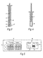
- Figures 1 and 2 show a continuous flight auger piling rig 1 including an auger 2.
- the rig is also provided with a rotation encoder 3 for measuring the speed of rotation of the auger and/or the number of revolutions of the auger and/or the torque applied to the auger.
- a depth encoder 4 for determining the depth of penetration of the auger into the ground. Concrete is supplied through a supply line 5 and the shaft of the auger 2 by way of an electromagnetic flowmeter 6 and a pressure sensor 7.
- the rotation encoder 3, depth encoder 4, flowmeter 6 and pressure sensor 7 are connected by way of data links to an electronic computer 8, incorporating a display unit 9, mounted in the cab of the rig 1.
- a printer 10 is connected to the computer 9.
- the rig 1 is operated so that the auger 2 undergoes a first, penetration phase as shown in Figure 3.
- the auger 2 is rotated and allowed to advance into the ground.
- Data obtained from the rotation encoder 3 and the depth encoder 4 are processed in the computer 8 so as to control the rotational speed and/or the advance of the auger 2 into the ground as a function of the ground conditions (which may be predetermined and/or monitored by way of the resistance presented to the auger 2 by the ground and other relevant parameters as measured by the rotation encoder 3 and the auger drive (not shown)).
- the penetration of the auger 2 is controlled so as to ensure that the flights 11 of the auger 2 are kept loaded with soil originating from the region of the auger tip 12. This mode of operation is specified in order to avoid loading of the auger flights 11 with soil from the bore wall 13.
- the concrete outflow at the tip 12 of the auger may be located at the extreme end 15 of the auger shaft or on at a location 16 on the side of the auger shaft just above the extreme end.
- the latter configuration is preferred, since fewer blockages occur.
- the display unit 9, shown in more detail in Figure 5, has two displays.
- the first display 17 shows the penetration of the auger per revolution and the second display 18 shows a graphical representation 19 of the position of the auger 2.
- the first display 17 shows data (which has been acquired by the computer 8) indicating where the auger 2 penetrates hard ground and gives warning of ground inconsistencies or the possibility of the auger 2 starting to load from the side instead of from the tip 12.
- the second display 18 displays data acquired by the computer 8 comprising a continuous record 20 of the concrete pressure measured by the pressure sensor 7, a record 21 of the concrete flow as measured by the flowmeter 6 and compared to a theoretical flow requirement, and a representation 19 of the position of the auger 2.
- the pressure display 20 indicates the conditions of concrete confinement during injection while the flow display 21 indicates whether the correct volume of concrete 14 or an excess has been supplied.
- Data stored in the computer 8, including the data displayed on display unit 9, may be printed out on the printer 10 and/or downloaded directly from the computer 8 to an external computer 80 (shown in Figure 1) for further analysis.
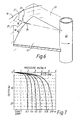
- the auger 2 performs two functions in that it cuts or digs the soil 22 and also transports it to the ground surface. These functions may not always be exactly compatible depending on the soil and the auger design and use.
- the auger stem 23 and its direction of rotation are shown with the edge of the flight 11 running against the effective soil wall 13.
- the soil element is acted upon by a radial force 24 at the auger periphery which is assumed to be equal to the active earth force from the soil outside the auger 2 (i.e. the force necessary to keep the bore wall 13 in equilibrium).
- the resultant of the vertical and horizontal interface forces is represented at 27.
- Soil rise in the borehole in relation to any penetration of the auger depends on two considerations:
- Equation (1) implies that there is a limit to the penetration rate, beyond which to screw the auger into the ground would mobilise forces analogous to 'bearing capacity' and extremely high torques would be required exceeding those available from conventional machines.
- Equation (2) implies that the forces acting on the chosen soil element depend on auger diameter, penetration turns per unit length and on the pitch of the auger flights 11.
- the driving force derives from the radial pressure acting to close the hole and a reasonable approach towards finding this is that given by Terzaghi in Theoretical Soil Mechanics (Wiley, New York, 1944) for pressures acting on the walls of a shaft. These are forces which represent the minimum value necessary to sustain the wall.
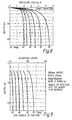
- Figure 7 shows typical lateral pressures in relation to depth for various shaft sizes in a sand with an angle of friction of 35°. It will be noted that for a small diameter shaft the pressures rapidly approach a near constant value with depth and the stability of the bore wall 13 is easier to maintain than in the case of a larger shaft. Also, the lateral force acting to drive soil up the auger is diminished as the shaft size is reduced.
- Figure 8 shows the effect of a change of the angle of friction of the soil mass outside the auger on the lateral pressure as depth increases for a 500mm pile shaft.
- lateral pressure in boreholes in Figures 7 and 8 may be confirmed in practice by the use of about 1m of differential pressure head in pile bores where construction is carried out using bentonite suspension.
- T s ⁇ .D.P.K H .tan ⁇ a acting at the angle ⁇ .
- the ratio Q 2 /Q 1 is a ratio between opposing forces, and for convenience will be called the Flighting Force Ratio (F R ).
- the auger would be expected to transport soil so long as (F R ) exceeds unity; and given that the ratio is greater than 1.0, the magnitude of the ratio (or excess force) would represent the potential to do work in transporting soil.
- the relation of Flighting Force Ratio to depth for a specific case is shown in Figure 9.
- An auger 2 turning with no peripheral friction would not transport soil and would therefore be very inefficient.
- An auger 2 in a soil with a very high angle of friction would have little lateral pressure available from the soil and would be an ineffective transporter.
- an auger 2 in a loose sand has a high lateral soil pressure exerted and will be efficient. Therefore, if its penetration rate is not fast enough to keep it fully loaded from the digging action at the base 12, it will load by inward failure of the bore wall 13 and consequently cause considerable ground disturbance in the immediate vicinity.
- the auger may be rotated during extraction and concrete placing or may simply be pulled without rotation in sandy soils. If rotation is used there is the possibility that some lateral loading will take place in sands depending on the over-supply of concrete which is imposed.
- a target for over-supply in the region of ⁇ 20% may be set.
- the pressures required to expand a pile shaft in sand at depth are large because of the large passive pressures which can be mobilised in a circular hole, and such pressures are not normally available from a conventional concrete pump.
- the object of over-supplying is in this case only to ensure that concrete rises relative to the auger 2 at all times.
- the depth encoder 4 can measure to within an accuracy of ⁇ 25mm so that it is possible to observe in detail that sufficient concrete has been carried up onto the auger 2 and that a good positive pressure is present before lifting commences. This has beneficial effects in that i) any void which may have occurred within the auger stem while the machine was moving between piles is eliminated, and ii) that concrete is carried up by, say, 0.5m in the pile in order to ensure that any loose debris is taken well away from the pile base. In order to achieve this it is necessary to rotate the auger 2 at this stage.
- the concrete supply pressure is usually measured at the top of the auger stem. If it is measured elsewhere lower down on the supply side then there will be an offset to the pressure delivery record.
- the pressure available at the delivery point at the auger tip 12 needs to have the pressure due to the head of concrete within the auger stem added so long as the measured pressure is above minus one atmosphere. Over most of the length of a pile, positive pressures would be expected at the auger head.
- the auger tip 12 approaches the ground and, if at that stage it is loaded with sand, then there may come a point where, though the auger 2 may still be embedded by several metres, the concrete escapes to the ground surface. At this point pressure measurement becomes meaningless and only concrete flow is then relevant.
- the concrete may escape to the ground surface by a mechanism similar to hydrofracture and it may pass up the underside of the flights to flow from the top of the bore.
- a preferred regime in concreting continuous flight augered piles is therefore to rotate the auger in the initial stages of concrete pumping in order to carry concrete up onto the auger and thereafter to cease rotation for the remainder of the extraction or to permit rotation throughout the lifting process only at a low or the lowest available speed.
- the concrete pressure is monitored at the auger head in the supply line 5.
- the pressure at the delivery point corresponds to the length of the auger 2, less a little allowance for friction.
- This pressure alone (minus one atmosphere if pumping is ceased) may be more than sufficient to cause borehole expansion.
- a pressure of about 200kN/m 2 would be necessary to expand the borehole.
Landscapes
- Engineering & Computer Science (AREA)
- Mining & Mineral Resources (AREA)
- Life Sciences & Earth Sciences (AREA)
- Structural Engineering (AREA)
- General Engineering & Computer Science (AREA)
- General Life Sciences & Earth Sciences (AREA)
- Geology (AREA)
- Paleontology (AREA)
- Civil Engineering (AREA)
- Physics & Mathematics (AREA)
- Geochemistry & Mineralogy (AREA)
- Fluid Mechanics (AREA)
- Environmental & Geological Engineering (AREA)
- Piles And Underground Anchors (AREA)
- Earth Drilling (AREA)
- Organic Low-Molecular-Weight Compounds And Preparation Thereof (AREA)
- Consolidation Of Soil By Introduction Of Solidifying Substances Into Soil (AREA)
- Drilling And Exploitation, And Mining Machines And Methods (AREA)
- Molds, Cores, And Manufacturing Methods Thereof (AREA)
- Perforating, Stamping-Out Or Severing By Means Other Than Cutting (AREA)
Claims (7)
- Verfahren zum Pfahlerzeugen mit einem Erdbohrer, der eine durchgehende Schnecke hat, wobei: .i) ein Erdbohrer (2) in den Boden eingebracht wird und dabei eine erste Eindringphase und eine zweite Rückziehphase durchläuft; undii) die Drehzahl, die Eindringgeschwindigkeit des Erdbohrers (2) und das auf den Erdbohrer ausgeübte Drehmoment während der ersten Eindringphase bestimmt und als Funktion der Bodeneigenschaften und der Erdbohrergeometrie geregelt werden, und zwar mit Hilfe eines elektronischen Computers (8) und mit dem Ziel, die Schneckenwindungen (11) des Erdbohrers mit Erdboden beladen zu halten, der aus dem Bereich der Spitze (12) des Erdbohrers (2) stammt, wobei der elektronische Computer (8) dafür ausgelegt ist, den Vorschub des Erdbohrers (2) so zu regeln, dass eine vorgegebene Anzahl an Erdbohrer-Umdrehungen pro Einheit der Eindringtiefe erreicht wird.
- Verfahren nach Anspruch 1, wobei:iii) der Spitze des Erdbohrers (2) während der zweiten Rückziehphase mit Hilfe von Flussregel- und Messvorrichtungen (6, 7) Beton (14) zugeführt wird; undiv) die Rückziehgeschwindigkeit des Erdbohrers (2) als Funktion der Flussrate des Betons (14) oder umgekehrt geregelt wird, und zwar mit Hilfe eines elektronischen Computers (8), damit sichergestellt ist, dass genügend Beton (14) zugeführt wird, so dass beim Zurückziehen zumindest die Spitze (12) des Erdbohrers (2) im Beton (14) eingetaucht bleibt.
- Verfahren nach Anspruch 1 oder 2, wobei der Erdbohrer (2) so angetrieben wird, dass er bis zu einer vorbestimmten Tiefe in den Erdboden eindringt, und bei dieser Tiefe der Vorschub des Erdbohrers (2) angehalten wird, so dass ein Abscheren des Erdbodens, der die Bohrlochwand (13) umgibt, erfolgen kann.
- Verfahren nach Anspruch 1, 2 oder 3, wobei die Schritte des Eindringens und Anhaltens wiederholt werden, bis der Erdbohrer (2) eine vorbestimmte Tiefe erreicht hat.
- Verfahren nach irgendeinem der vorhergehenden Ansprüche, wobei das größtmögliche verfügbare Drehmoment zum Antrieb des Erdbohrers (2) bestimmt wird, und wobei der Vorschub des Erdbohrers (2) angehalten wird, wenn das auf den Erdbohrer (2) ausgeübte Drehmoment eine vorbestimmte Größe bei der oder nahe an der größtmöglichen bestimmten Größe erreicht.
- Verfahren zum Pfahlerzeugen mit einem Erdbohrer, der eine durchgehende Schnecke hat, wobei:i) ein Erdbohrer (2) in den Boden eingebracht wird und dabei eine erste Eindringphase und eine zweite Rückziehphase durchläuft, wobei der Erdbohrer (2) mit Hilfe eines hydraulischen Bohrgestells zurückgezogen wird, das ein elektronisch gesteuertes Hydraulikventil aufweist, das der elektronische Computer (8) betätigt;ii) der Spitze (12) des Erdbohrers (2) während der zweiten Rückziehphase mit Hilfe eines elektromagnetischen Durchflussmessers (6) und einer Flussregelvorrichtung Beton (14) zugeführt wird; undiii) die Rückziehgeschwindigkeit des Erdbohrers (2) und die Flussrate des Betons (14) unabhängig gemäß einem vorgegebenen System geregelt werden, und zwar mit Hilfe eines elektronischen Computers (8), damit sichergestellt ist, dass genügend Beton (14) zugeführt wird, so dass beim Zurückziehen zumindest die Spitze (12) des Erdbohrers (2) im Beton (14) eingetaucht bleibt, und wobei mindestens 5 Prozent mehr Beton (14) zugeführt wird, als theoretisch zum Füllen eines Zylinders mit dem Durchmesser und der Länge des Bohrlochs erforderlich ist.
- Verfahren nach Anspruch 6, wobei 10 bis 35 Prozent mehr Beton (14) zugeführt wird, als theoretisch zum Füllen eines Zylinders mit dem Durchmesser und der Länge des Bohrlochs erforderlich ist.
Applications Claiming Priority (3)
| Application Number | Priority Date | Filing Date | Title |
|---|---|---|---|
| GB9515652 | 1995-07-31 | ||
| GB9515652A GB2303868B (en) | 1995-07-31 | 1995-07-31 | Improved auger piling |
| PCT/GB1996/001855 WO1997005334A1 (en) | 1995-07-31 | 1996-07-30 | Improved auger piling |
Publications (3)
| Publication Number | Publication Date |
|---|---|
| EP0842329A1 EP0842329A1 (de) | 1998-05-20 |
| EP0842329B1 EP0842329B1 (de) | 2000-02-09 |
| EP0842329B2 true EP0842329B2 (de) | 2004-11-17 |
Family
ID=10778526
Family Applications (1)
| Application Number | Title | Priority Date | Filing Date |
|---|---|---|---|
| EP96925898A Expired - Lifetime EP0842329B2 (de) | 1995-07-31 | 1996-07-30 | Verfahren zum erzeugen eines pfahles durch schneckenbohren |
Country Status (12)
| Country | Link |
|---|---|
| US (1) | US6116819A (de) |
| EP (1) | EP0842329B2 (de) |
| JP (1) | JPH11509900A (de) |
| CN (1) | CN1192793A (de) |
| AT (1) | ATE189725T1 (de) |
| AU (1) | AU714365B2 (de) |
| BR (1) | BR9609974A (de) |
| CA (1) | CA2228518C (de) |
| DE (1) | DE69606647T3 (de) |
| ES (1) | ES2145473T5 (de) |
| GB (2) | GB2303868B (de) |
| WO (1) | WO1997005334A1 (de) |
Cited By (1)
| Publication number | Priority date | Publication date | Assignee | Title |
|---|---|---|---|---|
| USD648193S1 (en) | 2003-02-18 | 2011-11-08 | Wheat Jamie L | Planting auger |
Families Citing this family (38)
| Publication number | Priority date | Publication date | Assignee | Title |
|---|---|---|---|---|
| GB9724024D0 (en) | 1997-11-13 | 1998-01-14 | Kvaerner Cementation Found Ltd | Improved piling method |
| RU2135691C1 (ru) * | 1998-11-10 | 1999-08-27 | Галай Борис Федорович | Способ возведения буронабивной сваи |
| CN1236514C (zh) * | 1999-02-26 | 2006-01-11 | 吉莱特公司 | 高性能碱性电池 |
| US6394703B1 (en) * | 1999-04-26 | 2002-05-28 | Cementations Foundations Skanska Limited | Formation of capping beams for piles |
| GB2355750B (en) * | 1999-10-30 | 2003-12-17 | Kvaerner Cementation Found Ltd | Forming piles |
| GB0013015D0 (en) * | 2000-05-26 | 2000-07-19 | Balfour Beatty Ltd | Auger piling |
| GB2362674A (en) * | 2000-05-26 | 2001-11-28 | Pennine Holdings Ltd | Auger with helical flight and fluid channel |
| FI115553B (fi) * | 2001-05-15 | 2005-05-31 | Sandvik Tamrock Oy | Järjestely porauksen ohjaukseen |
| RU2205262C2 (ru) * | 2001-07-25 | 2003-05-27 | Перцовский Михаил Израилевич | Способ возведения сваи |
| DE10238193B4 (de) * | 2002-08-21 | 2004-08-19 | Bauer Spezialtiefbau Gmbh | Bohrvorrichtung |
| DE10320662A1 (de) * | 2003-05-08 | 2004-12-02 | Bauer Maschinen Gmbh | Verfahren und Vorrichtung zur Bodenbearbeitung |
| DE10335366B4 (de) * | 2003-08-01 | 2005-06-16 | Bauer Spezialtiefbau Gmbh | Verfahren und Vorrichtung zum Herstellen einer Stabilisierungssäule im Boden |
| FR2858997B1 (fr) * | 2003-08-18 | 2006-03-31 | Bernard Coeuret | Equipement de travail des sols pour des travaux de forage et de plantation et poteaux utilisables avec un tel equipement |
| DE10338171B4 (de) * | 2003-08-20 | 2007-10-25 | Keller Grundbau Gmbh | Verfahren zum Einbringen eines schlanken Bodenpfahls und nach diesem Verfahren hergestellter Bodenpfahl |
| US7192220B2 (en) * | 2003-09-19 | 2007-03-20 | Gunther Johan M | Apparatus and method to prepare in-situ pilings with per-selected physical properties |
| US20050100415A1 (en) * | 2003-11-06 | 2005-05-12 | Larovere Tom A. | Profiler for installation of foundation screw anchors |
| US7198434B2 (en) * | 2004-07-13 | 2007-04-03 | Berkel & Company Contractors, Inc. | Full-displacement pressure grouted pile system and method |
| US20080131211A1 (en) * | 2004-07-13 | 2008-06-05 | Nesmith Willie M | Installation effort deep foudnation method |
| US7090436B2 (en) * | 2004-07-26 | 2006-08-15 | Gunther Johan M | Process to prepare in-situ pilings in clay soil |
| NL1028125C2 (nl) * | 2005-01-26 | 2006-07-27 | Ecodrie B V | Inrichting alsmede werkwijze voor het pompen van een uithardbare massa. |
| CN100386484C (zh) * | 2005-07-07 | 2008-05-07 | 何世鸣 | 一种水泥土桩 |
| US7341405B2 (en) * | 2006-02-13 | 2008-03-11 | Gunther Johan M | In-situ pilings with consistent properties from top to bottom and minimal voids |
| US7883295B2 (en) * | 2008-04-10 | 2011-02-08 | Schellhorn Verne L | Method and apparatus for forming an in situ subterranean soil cement structure having a cyclonic mixing region |
| US8261471B2 (en) | 2010-06-30 | 2012-09-11 | Hall David R | Continuously adjusting resultant force in an excavating assembly |
| DE102012109333A1 (de) * | 2012-10-01 | 2014-04-03 | Götz Hudelmaier | Vorrichtung und Verfahren zum Ausbilden eines Hohlraums im Boden zum Herstellen einer im Boden eingelassenen Ortbetonstruktur |
| DE102012109332A1 (de) * | 2012-10-01 | 2014-04-03 | Götz Hudelmaier | Verfahren und Vorrichtung zum Herstellen von im Boden eingelassenen Ortbetonstrukturen |
| EP3123167B1 (de) | 2014-03-28 | 2019-05-01 | Melvin Gerrard England | Verfahren und vorrichtung zur analyse von anomalien bei zementbauwerken |
| US20170350996A1 (en) * | 2016-06-03 | 2017-12-07 | Greenpowerusa Inc | Seismic Source Installation/Anchoring System and Method |
| CN106677166A (zh) * | 2016-12-21 | 2017-05-17 | 江苏省岩土工程公司 | 卵砾石――风化岩地层钻孔灌注桩双机联合成桩流水施工方法 |
| WO2019111190A1 (en) * | 2017-12-07 | 2019-06-13 | Soilmec Spa | Device to measure the flow rate of a fluid, such as concrete, in a pumping plant connected to a drilling machine |
| BE1024948B1 (nl) * | 2018-03-23 | 2018-08-23 | Injectis Bvba | Werkwijze en inrichting voor het behandelen van een bodem |
| EP3569769B1 (de) * | 2018-05-18 | 2021-08-11 | BAUER Spezialtiefbau GmbH | Gründungspfahl |
| CN109870259B (zh) * | 2019-02-14 | 2021-02-09 | 五邑大学 | 盾构螺旋输送机与改性渣土间等效剪切应力测定装置 |
| EP3819434B1 (de) | 2019-11-06 | 2022-02-16 | BAUER Maschinen GmbH | Verfahren und schlitzwandfräsvorrichtung zum erstellen eines frässchlitzes im boden |
| US20230349282A1 (en) * | 2022-04-28 | 2023-11-02 | Patriot Equipment Solutions, LLC | Auto-crowd control in mobile drill rigs based on soil condition |
| US20230390721A1 (en) * | 2022-06-07 | 2023-12-07 | Sub-Mergent Technologies, Inc. | Plunger mixer device |
| DE102023118181A1 (de) * | 2023-07-10 | 2025-01-16 | PST Spezialtiefbau Süd GmbH | Spezialtiefbau-Betoniertechnik für Bauvorhaben in Ballungsräumen |
| EP4497873B1 (de) | 2023-07-27 | 2025-10-29 | BAUER Maschinen GmbH | Vorrichtung und verfahren zum bilden eines bodenelementes |
Family Cites Families (15)
| Publication number | Priority date | Publication date | Assignee | Title |
|---|---|---|---|---|
| US3300988A (en) * | 1960-12-23 | 1967-01-31 | Raymond Int Inc | Apparatus for forming piles |
| US3200599A (en) * | 1960-12-23 | 1965-08-17 | Raymond Int Inc | Method for forming piles in situ |
| US4042043A (en) * | 1974-03-27 | 1977-08-16 | The Richmond Manufacturing Company | Portable earth boring machine |
| FR2318275A1 (fr) * | 1975-07-17 | 1977-02-11 | Labrue Jean Marie | Procede de realisation de pieux moules dans le sol et tariere creuse pour la mise en oeuvre du procede |
| GB2042029B (en) * | 1979-02-13 | 1982-11-17 | Chuan Pao Chen P | Method and apparatus for forming subterranean concrete piles |
| BE878215A (fr) * | 1979-08-13 | 1979-12-03 | Frankignoul Pieux Armes | Procede et dispositif de formation de pieux en beton moules dans le sol, au moyen d'une tariere |
| GB2064623A (en) * | 1979-10-15 | 1981-06-17 | Cementation Piling & Found | Apparatus for Working |
| JPS5927027A (ja) * | 1982-08-09 | 1984-02-13 | Hokkaido Kikai Kaihatsu Kk | 杭打用掘削機の運転制御方法 |
| GB2202885B (en) * | 1987-04-02 | 1990-11-07 | Westpile Int Uk Ltd | Piling and auger therefor |
| US5099696A (en) * | 1988-12-29 | 1992-03-31 | Takechi Engineering Co., Ltd. | Methods of determining capability and quality of foundation piles and of designing foundation piles, apparatus for measuring ground characteristics, method of making hole for foundation pile such as cast-in-situ pile and apparatus therefor |
| FR2642777B1 (fr) * | 1989-02-09 | 1991-05-24 | Sif Entreprise Bachy | Dispositif pour l'execution a la tariere continue creuse de pieux moules dans le sol |
| DE3905462A1 (de) * | 1989-02-22 | 1990-08-23 | Bauer Spezialtiefbau | Verfahren und messvorrichtung zur ermittlung des betonierdruckes |
| JPH0826540B2 (ja) * | 1989-06-02 | 1996-03-13 | 株式会社ジオトップ | ソイルセメント体の造成工法及びこれに用いるアースオーガー |
| US4958962A (en) * | 1989-06-28 | 1990-09-25 | Halliburton Company | Methods of modifying the structural integrity of subterranean earth situs |
| US5542786A (en) * | 1995-03-27 | 1996-08-06 | Berkel & Company Contractors, Inc. | Apparatus for monitoring grout pressure during construction of auger pressure grouted piling |
-
1995
- 1995-07-31 GB GB9515652A patent/GB2303868B/en not_active Expired - Fee Related
- 1995-07-31 GB GB9827373A patent/GB2328700B/en not_active Expired - Fee Related
-
1996
- 1996-07-30 JP JP9507369A patent/JPH11509900A/ja active Pending
- 1996-07-30 DE DE69606647T patent/DE69606647T3/de not_active Expired - Fee Related
- 1996-07-30 WO PCT/GB1996/001855 patent/WO1997005334A1/en not_active Ceased
- 1996-07-30 CA CA002228518A patent/CA2228518C/en not_active Expired - Fee Related
- 1996-07-30 US US09/011,239 patent/US6116819A/en not_active Expired - Fee Related
- 1996-07-30 EP EP96925898A patent/EP0842329B2/de not_active Expired - Lifetime
- 1996-07-30 AT AT96925898T patent/ATE189725T1/de not_active IP Right Cessation
- 1996-07-30 ES ES96925898T patent/ES2145473T5/es not_active Expired - Lifetime
- 1996-07-30 CN CN96196080A patent/CN1192793A/zh active Pending
- 1996-07-30 BR BR9609974A patent/BR9609974A/pt not_active Application Discontinuation
- 1996-07-30 AU AU66257/96A patent/AU714365B2/en not_active Ceased
Cited By (1)
| Publication number | Priority date | Publication date | Assignee | Title |
|---|---|---|---|---|
| USD648193S1 (en) | 2003-02-18 | 2011-11-08 | Wheat Jamie L | Planting auger |
Also Published As
| Publication number | Publication date |
|---|---|
| WO1997005334A1 (en) | 1997-02-13 |
| JPH11509900A (ja) | 1999-08-31 |
| GB9515652D0 (en) | 1995-09-27 |
| MX9800937A (es) | 1998-10-31 |
| AU714365B2 (en) | 1999-12-23 |
| BR9609974A (pt) | 1999-07-27 |
| DE69606647D1 (de) | 2000-03-16 |
| US6116819A (en) | 2000-09-12 |
| GB2303868A (en) | 1997-03-05 |
| EP0842329B1 (de) | 2000-02-09 |
| DE69606647T3 (de) | 2005-10-13 |
| ES2145473T5 (es) | 2005-04-01 |
| GB2303868B (en) | 1999-04-14 |
| ATE189725T1 (de) | 2000-02-15 |
| ES2145473T3 (es) | 2000-07-01 |
| GB2328700A (en) | 1999-03-03 |
| AU6625796A (en) | 1997-02-26 |
| GB9827373D0 (en) | 1999-02-03 |
| EP0842329A1 (de) | 1998-05-20 |
| GB2328700B (en) | 1999-04-14 |
| DE69606647T2 (de) | 2000-08-31 |
| CA2228518A1 (en) | 1997-02-13 |
| CN1192793A (zh) | 1998-09-09 |
| CA2228518C (en) | 2004-04-20 |
Similar Documents
| Publication | Publication Date | Title |
|---|---|---|
| EP0842329B2 (de) | Verfahren zum erzeugen eines pfahles durch schneckenbohren | |
| US7198434B2 (en) | Full-displacement pressure grouted pile system and method | |
| US20080131211A1 (en) | Installation effort deep foudnation method | |
| EP1030948B1 (de) | Verfahren für bohrungen und gründungspfählen | |
| EP1277887B1 (de) | Verdrängerbohrer und Gerät, welches den Bohrer benutzt | |
| Brown | Practical considerations in the selection and use of continuous flight auger and drilled displacement piles | |
| US4045966A (en) | Casingless pile method and apparatus | |
| EP4136295B1 (de) | System und verfahren zur konstruktion eines bohrlochpads | |
| Fleming | The Understanding of Continuous Flight Auger Piling, its Monitoring and Control.(includes Appendix). | |
| US3426538A (en) | Method of making sand drains in situ | |
| US5256005A (en) | Method and apparatus for placing cementitious materials in earth excavations | |
| HK1011394A (en) | Auger piling | |
| MXPA98000937A (en) | Method of stacking with barrena de paleta conti | |
| JP2791709B2 (ja) | シールド機の掘進制御方法 | |
| JPH07268878A (ja) | ケーソンの沈設方法およびケーソン刃口構造 | |
| EP0289147A2 (de) | Pfahlerzeugung | |
| GB2356659A (en) | Pile formation | |
| JP7567718B2 (ja) | 杭の施工方法及び該杭の施工方法に用いる潤滑剤の供給量の算出方法 | |
| CN114351686B (zh) | 一种适用于软弱地基土的挖方段就地固化设备及固化方法 | |
| CN121429279A (zh) | 一种可实现向下掘进的圆环状取土施工装备及其施工方法 | |
| JP2004346615A (ja) | 泥水式推進工法およびそれに用いる装置 | |
| GB2355750A (en) | Forming piles | |
| WO2000042256A1 (en) | Composite auger piling | |
| Lacy et al. | Reduced impact on adjacent structures using augered cast-in-place piles | |
| CN121381608A (zh) | 一种钻孔灌注桩施工方法 |
Legal Events
| Date | Code | Title | Description |
|---|---|---|---|
| PUAI | Public reference made under article 153(3) epc to a published international application that has entered the european phase |
Free format text: ORIGINAL CODE: 0009012 |
|
| 17P | Request for examination filed |
Effective date: 19980223 |
|
| AK | Designated contracting states |
Kind code of ref document: A1 Designated state(s): AT BE CH DE DK ES FI FR GR IE IT LI LU MC NL PT SE |
|
| AX | Request for extension of the european patent |
Free format text: AL PAYMENT 980223;LT PAYMENT 980223;LV PAYMENT 980223;SI PAYMENT 980223 |
|
| 17Q | First examination report despatched |
Effective date: 19980602 |
|
| GRAG | Despatch of communication of intention to grant |
Free format text: ORIGINAL CODE: EPIDOS AGRA |
|
| GRAG | Despatch of communication of intention to grant |
Free format text: ORIGINAL CODE: EPIDOS AGRA |
|
| GRAH | Despatch of communication of intention to grant a patent |
Free format text: ORIGINAL CODE: EPIDOS IGRA |
|
| GRAH | Despatch of communication of intention to grant a patent |
Free format text: ORIGINAL CODE: EPIDOS IGRA |
|
| RBV | Designated contracting states (corrected) |
Designated state(s): AT BE CH DE DK ES FI FR GR IE IT LI LU MC NL PT SE |
|
| GRAA | (expected) grant |
Free format text: ORIGINAL CODE: 0009210 |
|
| AK | Designated contracting states |
Kind code of ref document: B1 Designated state(s): AT BE CH DE DK ES FI FR GR IE IT LI LU MC NL PT SE |
|
| AX | Request for extension of the european patent |
Free format text: AL PAYMENT 19980223;LT PAYMENT 19980223;LV PAYMENT 19980223;SI PAYMENT 19980223 |
|
| LTIE | Lt: invalidation of european patent or patent extension | ||
| PG25 | Lapsed in a contracting state [announced via postgrant information from national office to epo] |
Ref country code: LI Free format text: LAPSE BECAUSE OF FAILURE TO SUBMIT A TRANSLATION OF THE DESCRIPTION OR TO PAY THE FEE WITHIN THE PRESCRIBED TIME-LIMIT Effective date: 20000209 Ref country code: GR Free format text: LAPSE BECAUSE OF NON-PAYMENT OF DUE FEES Effective date: 20000209 Ref country code: FI Free format text: LAPSE BECAUSE OF FAILURE TO SUBMIT A TRANSLATION OF THE DESCRIPTION OR TO PAY THE FEE WITHIN THE PRESCRIBED TIME-LIMIT Effective date: 20000209 Ref country code: CH Free format text: LAPSE BECAUSE OF FAILURE TO SUBMIT A TRANSLATION OF THE DESCRIPTION OR TO PAY THE FEE WITHIN THE PRESCRIBED TIME-LIMIT Effective date: 20000209 Ref country code: AT Free format text: LAPSE BECAUSE OF FAILURE TO SUBMIT A TRANSLATION OF THE DESCRIPTION OR TO PAY THE FEE WITHIN THE PRESCRIBED TIME-LIMIT Effective date: 20000209 |
|
| REF | Corresponds to: |
Ref document number: 189725 Country of ref document: AT Date of ref document: 20000215 Kind code of ref document: T |
|
| REG | Reference to a national code |
Ref country code: CH Ref legal event code: EP |
|
| REF | Corresponds to: |
Ref document number: 69606647 Country of ref document: DE Date of ref document: 20000316 |
|
| REG | Reference to a national code |
Ref country code: IE Ref legal event code: FG4D |
|
| ITF | It: translation for a ep patent filed | ||
| PG25 | Lapsed in a contracting state [announced via postgrant information from national office to epo] |
Ref country code: SE Free format text: LAPSE BECAUSE OF FAILURE TO SUBMIT A TRANSLATION OF THE DESCRIPTION OR TO PAY THE FEE WITHIN THE PRESCRIBED TIME-LIMIT Effective date: 20000509 Ref country code: PT Free format text: LAPSE BECAUSE OF FAILURE TO SUBMIT A TRANSLATION OF THE DESCRIPTION OR TO PAY THE FEE WITHIN THE PRESCRIBED TIME-LIMIT Effective date: 20000509 Ref country code: DK Free format text: LAPSE BECAUSE OF FAILURE TO SUBMIT A TRANSLATION OF THE DESCRIPTION OR TO PAY THE FEE WITHIN THE PRESCRIBED TIME-LIMIT Effective date: 20000509 |
|
| ET | Fr: translation filed | ||
| REG | Reference to a national code |
Ref country code: ES Ref legal event code: FG2A Ref document number: 2145473 Country of ref document: ES Kind code of ref document: T3 |
|
| PG25 | Lapsed in a contracting state [announced via postgrant information from national office to epo] |
Ref country code: LU Free format text: LAPSE BECAUSE OF NON-PAYMENT OF DUE FEES Effective date: 20000730 |
|
| PG25 | Lapsed in a contracting state [announced via postgrant information from national office to epo] |
Ref country code: MC Free format text: THE PATENT HAS BEEN ANNULLED BY A DECISION OF A NATIONAL AUTHORITY Effective date: 20000731 |
|
| REG | Reference to a national code |
Ref country code: CH Ref legal event code: PL |
|
| PLBE | No opposition filed within time limit |
Free format text: ORIGINAL CODE: 0009261 |
|
| PLBQ | Unpublished change to opponent data |
Free format text: ORIGINAL CODE: EPIDOS OPPO |
|
| PLAA | Information modified related to event that no opposition was filed |
Free format text: ORIGINAL CODE: 0009299DELT |
|
| PLBI | Opposition filed |
Free format text: ORIGINAL CODE: 0009260 |
|
| 26N | No opposition filed | ||
| PLBF | Reply of patent proprietor to notice(s) of opposition |
Free format text: ORIGINAL CODE: EPIDOS OBSO |
|
| 26 | Opposition filed |
Opponent name: BAUER SPEZIALTIEFBAU GMBH Effective date: 20001109 |
|
| D26N | No opposition filed (deleted) | ||
| RAP2 | Party data changed (patent owner data changed or rights of a patent transferred) |
Owner name: CEMENTATION FOUNDATIONS SKANSKA LIMITED |
|
| REG | Reference to a national code |
Ref country code: ES Ref legal event code: PC2A |
|
| NLR1 | Nl: opposition has been filed with the epo |
Opponent name: BAUER SPEZIALTIEFBAU GMBH |
|
| NLT1 | Nl: modifications of names registered in virtue of documents presented to the patent office pursuant to art. 16 a, paragraph 1 |
Owner name: CEMENTATION FOUNDATIONS SKANSKA LIMITED |
|
| NLT2 | Nl: modifications (of names), taken from the european patent patent bulletin |
Owner name: CEMENTATION FOUNDATIONS SKANSKA LIMITED |
|
| REG | Reference to a national code |
Ref country code: FR Ref legal event code: CD |
|
| PLBF | Reply of patent proprietor to notice(s) of opposition |
Free format text: ORIGINAL CODE: EPIDOS OBSO |
|
| PLBP | Opposition withdrawn |
Free format text: ORIGINAL CODE: 0009264 |
|
| PUAH | Patent maintained in amended form |
Free format text: ORIGINAL CODE: 0009272 |
|
| STAA | Information on the status of an ep patent application or granted ep patent |
Free format text: STATUS: PATENT MAINTAINED AS AMENDED |
|
| 27A | Patent maintained in amended form |
Effective date: 20041117 |
|
| AK | Designated contracting states |
Kind code of ref document: B2 Designated state(s): AT BE CH DE DK ES FI FR GR IE IT LI LU MC NL PT SE |
|
| AX | Request for extension of the european patent |
Extension state: AL LT LV SI |
|
| NLR2 | Nl: decision of opposition |
Effective date: 20041117 |
|
| NLR3 | Nl: receipt of modified translations in the netherlands language after an opposition procedure | ||
| REG | Reference to a national code |
Ref country code: ES Ref legal event code: DC2A Date of ref document: 20041126 Kind code of ref document: T5 |
|
| ET3 | Fr: translation filed ** decision concerning opposition | ||
| PGFP | Annual fee paid to national office [announced via postgrant information from national office to epo] |
Ref country code: NL Payment date: 20080721 Year of fee payment: 13 |
|
| PGFP | Annual fee paid to national office [announced via postgrant information from national office to epo] |
Ref country code: ES Payment date: 20090622 Year of fee payment: 14 |
|
| PGFP | Annual fee paid to national office [announced via postgrant information from national office to epo] |
Ref country code: BE Payment date: 20090622 Year of fee payment: 14 |
|
| PGFP | Annual fee paid to national office [announced via postgrant information from national office to epo] |
Ref country code: FR Payment date: 20090727 Year of fee payment: 14 |
|
| PGFP | Annual fee paid to national office [announced via postgrant information from national office to epo] |
Ref country code: DE Payment date: 20090728 Year of fee payment: 14 |
|
| NLV4 | Nl: lapsed or anulled due to non-payment of the annual fee |
Effective date: 20100201 |
|
| PGFP | Annual fee paid to national office [announced via postgrant information from national office to epo] |
Ref country code: IT Payment date: 20090722 Year of fee payment: 14 |
|
| BERE | Be: lapsed |
Owner name: *CEMENTATION FOUNDATIONS SKANSKA LTD Effective date: 20100731 |
|
| REG | Reference to a national code |
Ref country code: FR Ref legal event code: ST Effective date: 20110331 |
|
| PG25 | Lapsed in a contracting state [announced via postgrant information from national office to epo] |
Ref country code: DE Free format text: LAPSE BECAUSE OF NON-PAYMENT OF DUE FEES Effective date: 20110201 |
|
| REG | Reference to a national code |
Ref country code: DE Ref legal event code: R119 Ref document number: 69606647 Country of ref document: DE Effective date: 20110201 |
|
| PG25 | Lapsed in a contracting state [announced via postgrant information from national office to epo] |
Ref country code: IT Free format text: LAPSE BECAUSE OF NON-PAYMENT OF DUE FEES Effective date: 20100730 Ref country code: FR Free format text: LAPSE BECAUSE OF NON-PAYMENT OF DUE FEES Effective date: 20100802 |
|
| PG25 | Lapsed in a contracting state [announced via postgrant information from national office to epo] |
Ref country code: BE Free format text: LAPSE BECAUSE OF NON-PAYMENT OF DUE FEES Effective date: 20100731 |
|
| REG | Reference to a national code |
Ref country code: ES Ref legal event code: FD2A Effective date: 20110818 |
|
| PG25 | Lapsed in a contracting state [announced via postgrant information from national office to epo] |
Ref country code: ES Free format text: LAPSE BECAUSE OF NON-PAYMENT OF DUE FEES Effective date: 20100731 |
|
| PG25 | Lapsed in a contracting state [announced via postgrant information from national office to epo] |
Ref country code: NL Free format text: LAPSE BECAUSE OF NON-PAYMENT OF DUE FEES Effective date: 20100201 |
|
| PGFP | Annual fee paid to national office [announced via postgrant information from national office to epo] |
Ref country code: IE Payment date: 20120821 Year of fee payment: 17 |
|
| REG | Reference to a national code |
Ref country code: IE Ref legal event code: MM4A |
|
| PG25 | Lapsed in a contracting state [announced via postgrant information from national office to epo] |
Ref country code: IE Free format text: LAPSE BECAUSE OF NON-PAYMENT OF DUE FEES Effective date: 20130730 |