EP4136295B1 - System und verfahren zur konstruktion eines bohrlochpads - Google Patents
System und verfahren zur konstruktion eines bohrlochpads Download PDFInfo
- Publication number
- EP4136295B1 EP4136295B1 EP20729189.9A EP20729189A EP4136295B1 EP 4136295 B1 EP4136295 B1 EP 4136295B1 EP 20729189 A EP20729189 A EP 20729189A EP 4136295 B1 EP4136295 B1 EP 4136295B1
- Authority
- EP
- European Patent Office
- Prior art keywords
- cellar
- area
- construction area
- construction
- clsm
- Prior art date
- Legal status (The legal status is an assumption and is not a legal conclusion. Google has not performed a legal analysis and makes no representation as to the accuracy of the status listed.)
- Active
Links
Images


Classifications
-
- E—FIXED CONSTRUCTIONS
- E21—EARTH OR ROCK DRILLING; MINING
- E21B—EARTH OR ROCK DRILLING; OBTAINING OIL, GAS, WATER, SOLUBLE OR MELTABLE MATERIALS OR A SLURRY OF MINERALS FROM WELLS
- E21B15/00—Supports for the drilling machine, e.g. derricks or masts
- E21B15/006—Means for anchoring the drilling machine to the ground
-
- E—FIXED CONSTRUCTIONS
- E21—EARTH OR ROCK DRILLING; MINING
- E21B—EARTH OR ROCK DRILLING; OBTAINING OIL, GAS, WATER, SOLUBLE OR MELTABLE MATERIALS OR A SLURRY OF MINERALS FROM WELLS
- E21B33/00—Sealing or packing boreholes or wells
- E21B33/02—Surface sealing or packing
- E21B33/03—Well heads; Setting-up thereof
- E21B33/035—Well heads; Setting-up thereof specially adapted for underwater installations
- E21B33/037—Protective housings therefor
-
- E—FIXED CONSTRUCTIONS
- E02—HYDRAULIC ENGINEERING; FOUNDATIONS; SOIL SHIFTING
- E02D—FOUNDATIONS; EXCAVATIONS; EMBANKMENTS; UNDERGROUND OR UNDERWATER STRUCTURES
- E02D17/00—Excavations; Bordering of excavations; Making embankments
- E02D17/02—Foundation pits
-
- E—FIXED CONSTRUCTIONS
- E04—BUILDING
- E04B—GENERAL BUILDING CONSTRUCTIONS; WALLS, e.g. PARTITIONS; ROOFS; FLOORS; CEILINGS; INSULATION OR OTHER PROTECTION OF BUILDINGS
- E04B1/00—Constructions in general; Structures which are not restricted either to walls, e.g. partitions, or floors or ceilings or roofs
- E04B1/0007—Base structures; Cellars
- E04B1/0015—Cellars constructed from prefabricated units
-
- E—FIXED CONSTRUCTIONS
- E21—EARTH OR ROCK DRILLING; MINING
- E21B—EARTH OR ROCK DRILLING; OBTAINING OIL, GAS, WATER, SOLUBLE OR MELTABLE MATERIALS OR A SLURRY OF MINERALS FROM WELLS
- E21B33/00—Sealing or packing boreholes or wells
- E21B33/10—Sealing or packing boreholes or wells in the borehole
- E21B33/13—Methods or devices for cementing, for plugging holes, crevices or the like
- E21B33/14—Methods or devices for cementing, for plugging holes, crevices or the like for cementing casings into boreholes
Definitions
- the subject matter described herein relates to systems, methods, and materials for preparing well pads to install drilling rigs and drill boreholes.
- a well pad construction system is defined by the appended system claim.
- the well pad construction system includes: a construction area; an excavator disposed at the construction area; a cellar disposed within the excavated area; controlled low-strength material (CLSM); and backfill equipment disposed around the excavated area at the construction area.
- the excavator is moveable over the construction area to generate an excavated area.
- the backfill equipment is moveable to pour CLSM into a gap between the cellar and surrounding medium in the excavated area for holding the cellar in place.
- the compactor applies high energy impact compaction (HEIC) at the construction area.
- HEIC high energy impact compaction
- the CLSM includes water, cement, and fine aggregates.
- the CLSM includes byproduct materials.
- the expected maximum strength of the CLSM is about 8.3 MPa (1200 psi).
- the cellar is composed of at least one of steel, aluminum, concrete, reinforced concrete, fiberglass, and fiberglass-reinforced plastic.
- the cellar includes a shape of at least one of a cuboid, a box, a cylinder, a barrel, a bowl, and combinations thereof.
- the sides and bottom of the cellar include a crack-resistant material.
- the top and the bottom of the cellar are at least partially open.
- the system further includes: a drilling rig disposed longitudinally above the cellar; and a drill pipe disposed longitudinally below the drilling rig.
- the drill pipe passes through a top and a bottom of the cellar for drilling a borehole downward below the cellar.
- a method of preparing a well pad according to the invention is defined by the appended method claim.
- the method includes: identifying a construction area; compacting the construction area to generate a compacted medium within the construction area; excavating the compacted medium using an excavator; installing a cellar in the excavated area; and backfilling a gap between the cellar and surrounding medium with a backfill material.
- Compacting the construction area uses high energy impact compaction (HEIC).
- HEIC high energy impact compaction
- Excavating the compacted medium creates an excavated area within the compacted medium.
- the backfill material includes controlled low-strength material (CLSM).
- CLSM controlled low-strength material
- the cellar is disposed near or at the center of the excavated area.
- the system further includes installing at least one drilling rig at the construction area.
- the at least one drilling rig is disposed longitudinally above the cellar.
- preparing the well pad takes up to about 3 days.
- the compactor uses high energy impact compaction (HEIC).
- HEIC high energy impact compaction
- the present disclosure is also directed to a drilling site including: a compacted medium including an excavated area; a cellar disposed within the excavated area; backfill material disposed between the cellar and the compacted medium; a drilling rig disposed longitudinally above the cellar; and a drill pipe disposed longitudinally below the drilling rig, the drill pipe passing through a top and a bottom of the cellar for drilling a borehole downward below the cellar.
- the cellar may include at least one of a box shape, a cuboid shape, and a cylinder shape.
- the backfill material may consist of CLSM.
- the systems, methods, and materials may reduce the amount of materials (such as soil) that need to be transported to the site for backfilling, in an exemplary method.
- the system may use work crews, equipment (for example, trucks, cranes, loaders, compactors, excavators, skid steers, and/or combinations thereof), cellars, and backfill materials (preferably controlled low-strength material (CLSM)), to reduce the time and cost for the well pad construction.
- CLSM controlled low-strength material
- the methods may include processes of compacting, excavating, installing, and backfilling for well pad preparation and/or construction.
- the method may also be used for compaction in cases where water tables are present.
- the present embodiments may include a compaction technique (for example, high energy impact compaction (HEIC)) to achieve the required compaction level (for example, 95% compaction or 95% maximum dry density using the modified Proctor test designated by ASTM D-1557).
- HEIC high energy impact compaction
- the present system and methods do not require watering for compaction, transportation of materials during construction (for example, during excavation or backfilling), or layer-by-layer compaction.
- the present disclosed embodiments also reduces: the space required for excavation and backfilling, the required backfill materials, dust, and traffic at the wellsite, and the number of quality control tests, thereby resulting in reduced cost and time for well pad construction.
- a well pad construction using the present disclosed embodiments may be accomplished in up to about 3 days compared with about 10 days when using conventional systems, methods, and materials.
- the systems, methods, and materials may use HEIC for compaction (when compaction is required) and CLSM for backfilling to expedite the construction of the wellsite and achieve desired engineering properties with minimal disturbance to existing site conditions and surrounding areas.
- HEIC may be selected as an effective compaction method in terms of achieving the required compaction depth, the ease of use, and the ease of transportation to the construction site.
- the step of compaction may be conducted before the steps of excavation and installation.
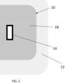
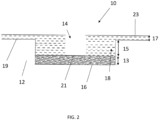
- Figs. 1-2 illustrate top and cross-section views of an exemplary well pad 10 formed within a medium 12.
- the exemplary well pad 10 may be excavated from the medium 12 and may include a periphery in the shape of a rectangle, prism, cube, and/or other shape.
- a bottom pad 16 may be disposed at the bottom of the exemplary well pad 10 and filled with loose backfill material (for example, dry compacted marl, or other materials) with a first depth 13.
- the first depth 13 may be up to about 1.2m.
- the first depth 13 may be up to about 0.9m.
- the first depth 13 may be up to about 0.6m.
- the first depth 13 may be up to about 0.4m.
- the first depth 13 may be up to about 0.1m. In one embodiment, the first depth 13 may be about 0.3m.
- a cellar 14 may be disposed longitudinally above the bottom pad 16 within the exemplary well pad 10. The cellar 14 may be near or in the middle of the exemplary well pad 10 and may include a periphery in the shape of a rectangle, prism, cube, and/or other shape.
- a gap or a plurality of gaps 18 including space between the cellar 14 and surrounding medium may be backfilled by layers of a second loose backfill material (for example, wet compacted marl or other materials) to hold the cellar 14 in place, and to provide a firm well pad for one or more rigs to stand on and operate from.
- a second loose backfill material for example, wet compacted marl or other materials
- the third depth 17 may be up to about 1m. In some embodiments, the third depth 17 may be up to about 0.6m. In some embodiments, the third depth 17 may be up to about 0.3m. In some embodiments, the third depth 17 may be up to about 0.1m. In one embodiment, the third depth 17 may be about 0.15m.
- Both the gap 18 and the cellar 14 may include a shape of a cuboid, cylinder, bowl, and/or combinations thereof. In some embodiments of Fig. 2 , the gap 18 may be at least partially wider or longer than the cellar 14.
- the exemplary well pad 10 may be up to 25m x 25m in area with a depth of up to about 4.27m, and the cellar 14 may be about 3.96m x about 6.71m in area with a depth of up to about 4.27m.
- an overall exemplary wellsite may be up to 140m x 140m in area.
- Each layer of the backfill may be up to about 0.2m thick.
- the exemplary well pad 10 may be up to 75m x 75m in area with a depth of up to about up to10m; the cellar 14 may be from about 10m x up to about 15m in area with a depth of up to about 10m; the overall exemplary wellsite may be up to 250m x 250m in area; and/or each layer of the backfill may be up to about 0.6m thick.
- the cellar 14 may be from about 10m x up to about 15m in area with a depth of up to about 10m; the overall exemplary wellsite may be up to 250m x 250m in area; and/or each layer of the backfill may be up to about 0.6m thick.
- the well pad construction including excavating the area, installing the cellar 14, backfilling, and compacting the area in layers, may take about 10 days to complete and may also need watering for each layer and sometimes transportation of materials for backfilling.
- a surface tolerance may be within about ⁇ 3cm of the planned location elevation within 25m of the wellhead and ⁇ 8cm of planned location elevation throughout the rest of the location.
- Ramps (not shown) may be built on one or two sides of the excavation (for example, on either side of the cellar) to allow access for construction equipment.
- the effect (for example, depth) of compaction may vary with the characteristics (for example, component and moisture) of the construction area 20 and the specific energy input.
- the depth of compaction for natural marine sand and clay fill using HEIC may be up to about 4m, about 5m, about 6m, and/or about 7m depending on several factors which may include: the composition of the compaction media, the coarseness or fineness of the particles, the level of moisture in the compaction media, how loosely packed the media is initially, as well as other factors.
- the depth of compaction for natural marine sand and clay fill using HEIC may be up to about 6m and up to about 7m, respectively.
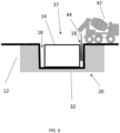
- Fig. 4 illustrates a side view of excavation of the construction area 20, according to aspects of the present embodiments.
- An excavator 34 may be disposed on the medium surface 11 to dig the compacted medium 32 out of the construction area 20.
- the excavator 34 may include a cab 35, an arm 36, and a bucket 38.
- the distal end of the arm 36 may be operatively coupled to the bucket 38.
- the bucket 38 may include a side cutter 40 for cleanup, digging, and/or levelling the compacted medium 32.
- the edge 39 of the side cutter 40 may be straight, wavy (that is, teeth-shape), or a combination of both.
- the bucket 38 may have different shapes and sizes.
- the excavator 34 may include a tiltrotator (not shown) for the bucket 38 and/or other attachments to rotate 360 degrees and tilt about + or - 45 degrees to increase the flexibility and precision of the excavator 34.
- the present disclosed embodiments may include a single excavator 34, but other embodiments may include multiple excavators 34. Using the present embodiments, excavation may be achieved by the excavating action and/or work crew. After excavation, an excavated area 37 may be slightly wider than the cellar 14.
- both the cellar 14 and the gap 18 may include geometries that are cuboid, box, cylinder, barrel, bowl, and/or combinations thereof.
- the gap(s) 18 may be significantly, or at least partially, narrower or smaller than the cellar 14.
- the cellar 14 may be a box with dimensions of up to about 3.96m x up to about 6.71m and/or up to about 4.27m deep (for example, for gas drilling pads).
- the cellar 14 may be a box with dimensions of up to about 5m in width, up to about 8m in length, and/or up to about 5m deep.
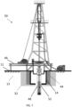
- Fig. 7 illustrates a side view of a borehole 48 formed by using a drilling rig 50 longitudinally above the cellar 14, according to aspects of the present embodiments.
- the drilling rig 50 may be installed on the prepared well pad and may include a rig floor 46.
- the work crew may work primarily on the rig floor 46 above the medium surface 11 to install a drill pipe 52 through the open end of the cellar 14 and to drill in the borehole 48 within the formation using the drill pipe 52.
- the present disclosed embodiments may include a single drilling rig 50, but other embodiments may include multiple drilling rigs 50.
- one or more rig pads or well pads 10 may be constructed.
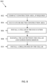
- Fig. 8 illustrates a schematic of an exemplary method 800 of constructing a well pad for drilling operations, according to aspects of the present embodiments.
- the method 800 may include compacting construction area, if required.
- the method 800 may include filling the construction area 20 to a certain level before compacting, and then start step 802.
- the construction area may include leveling and/or spreading material from one or more areas of the construction area to other areas(s) such that the construction area is generally flat prior to the initiating compaction operations.
- the method 800 may include excavating or digging the construction area 20 using an excavator 34.
- the method 800 may include installing a cellar 14 in the construction area 20.
- an apparatus, system, or method described herein as “comprising” one or more named elements or steps is open-ended, meaning that the named elements or steps are essential, but other elements or steps may be added within the scope of the apparatus, system, or method.
- any apparatus, system, or method described as “comprising” (or which "comprises") one or more named elements or steps also describes the corresponding, more limited apparatus system, or method “consisting essentially of” (or which "consists essentially of”) the same named elements or steps, meaning that the apparatus, system, or method includes the named essential elements or steps and may also include additional elements or steps that do not materially affect the basic and novel characteristic(s) of the system, apparatus, or method.
- any apparatus, system, or method described herein as “comprising” or “consisting essentially of” one or more named elements or steps also describes the corresponding, more limited, and closed-ended apparatus, system, or method “consisting of” (or “consists of") the named elements or steps to the exclusion of any other unnamed element or step.
- any apparatus, system, or method disclosed herein known or disclosed equivalents of any named essential element or step may be substituted for that element or step.
- reaction may be used to describe a process of pressing grains in a medium together to consolidate the medium, resulting in the reduction of pore space, pore fluids, and formation of rock, and also resulting in an increase in the bulk density of the medium.
- a “compactor” may be used to describe a machine used to drive over a medium to reduce the size or the volume of the medium. It may be powered by hydraulics, and may include various shapes and sizes.
- drum or “impact roller” may vary in weight, shape, compaction coverage, and drop height, resulting in a variation in the specific energy input and consequently the depth of influence and the magnitude of increase in the in-situ medium strength.
- the term "cellar” may be used to describe a cavity or box that is inserted in an excavated area, possibly lined with wood, cement, or thin-wall pipe with a large diameter (for example, about 1.8m), located below the drilling rig.
- the cellar may serve as a cavity in which the casing spool and casing head reside.
- the cellar may include an open-ended top and bottom through which a drill pipe may pass and drill a borehole below the cellar. Prior to setting of the surface casing, the cellar may also take mud that may return from the well, which may be pumped back to the surface equipment.
Landscapes
- Engineering & Computer Science (AREA)
- Geology (AREA)
- Life Sciences & Earth Sciences (AREA)
- Mining & Mineral Resources (AREA)
- Environmental & Geological Engineering (AREA)
- Fluid Mechanics (AREA)
- Physics & Mathematics (AREA)
- General Life Sciences & Earth Sciences (AREA)
- Geochemistry & Mineralogy (AREA)
- Mechanical Engineering (AREA)
- Investigation Of Foundation Soil And Reinforcement Of Foundation Soil By Compacting Or Drainage (AREA)
- On-Site Construction Work That Accompanies The Preparation And Application Of Concrete (AREA)
- Earth Drilling (AREA)
Claims (15)
- Ein System zur Konstruktion eines Bohrlochs, aufweisend:einen Konstruktionsbereich (20);einen Bagger (34), der in dem Konstruktionsbereich (20) angeordnet ist, wobei der Bagger (34) über den Konstruktionsbereich (20) bewegbar ist, um einen Aushubbereich (37) zu erzeugen;einen Keller (14), der innerhalb des Aushubbereichs (37) angeordnet ist;kontrolliertes niedrigfestes Material (CLSM);eine Verfüllungsvorrichtung (42), die um den Aushubbereich (37) im Konstruktionsbereich (20) angeordnet ist, wobei die Verfüllungsvorrichtung (42) beweglich ist, um CLSM in einen Spalt (18) zwischen dem Keller (14) und dem umgebenden Medium (12) im Aushubbereich (37) zu gießen, um den Keller (14) an Ort und Stelle zu halten; und gekennzeichnet durcheinen Verdichter (22), der in dem Konstruktionsbereich (20) angeordnet ist, wobei der Verdichter (22) über den Konstruktionsbereich (20) bewegbar ist, wobei der Verdichter (22) eine Schlagwalze (26) zum Verdichten des Aushubbereichs (37) vor dem Aushub aufweist, wobei der Verdichter (22) eine Hochenergie-Schlagverdichtung (HEIC) in dem Konstruktionsbereich (20) anwendet.
- System nach Anspruch 1, wobei die Schlagwalze (26) eine nicht zylindrische Schlagwalze mit drei abgerundeten Nocken (28) aufweist, die durch drei Gelenke (30) verbunden sind, wobei jeder abgerundete Nocken (28) einen Zylinder von etwa 120° bis etwa 180° aufweist.
- System nach Anspruch 1, wobei das CLSM Wasser, Zement und feine Aggregate aufweist.
- System nach Anspruch 1, wobei das CLSM Nebenproduktmaterialien aufweist.
- System nach Anspruch 1, wobei die erwartete maximale Festigkeit des CLSM etwa 8,3 MPa (1200 psi) beträgt.
- System nach Anspruch 1, wobei der Keller (14) aus mindestens einem der Materialien Stahl, Aluminium, Beton, Stahlbeton, Glasfaser und glasfaserverstärktem Kunststoff besteht.
- System nach Anspruch 1, wobei der Keller (14) eine Form von mindestens einem Quader, einer Box, einem Zylinder, einem Fass, einer Schale und Kombinationen davon aufweist.
- System nach Anspruch 1, wobei die Seiten und der Boden des Kellers (14) ein rissfestes Material aufweisen.
- System nach Anspruch 1, bei dem die Oberseite und der Boden des Kellers (14) zumindest teilweise offen sind.
- System nach Anspruch 1, das ferner aufweist:ein Bohrgestänge (50), das in Längsrichtung oberhalb des Kellers (14) angeordnet ist; undein Bohrgestänge (52), das in Längsrichtung unterhalb des Bohrgestänges (50) angeordnet ist, wobei das Bohrgestänge (52) durch die Oberseite und den Boden des Kellers (14) verläuft, um ein Bohrloch (48) nach unten unterhalb des Kellers zu bohren.
- Ein Verfahren zur Vorbereitung eines Bohrlochs, das folgende Schritte aufweist:Identifizierung eines Konstruktionsbereichs (20);Verdichten des Konstruktionsbereichs (20), um ein verdichtetes Medium (32) innerhalb des Konstruktionsbereichs (20) zu erzeugen;Ausheben des verdichteten Mediums (32) unter Verwendung eines Baggers (34), wobei das Ausheben des verdichteten Mediums (32) einen Aushubbereich (37) innerhalb des verdichteten Mediums (32) erzeugt;Einrichten eines Kellers (14) in der Nähe oder in der Mitte des Aushubbereichs (37); undAuffüllen einer Lücke (18) zwischen dem Keller (14) und dem umgebenden Medium (12) mit einem Auffüllmaterial (44), gekennzeichnet durchVerdichten des Konstruktionsbereichs (20) unter selektiver Verwendung von Hochenergie-Schlagverdichtung (HEIC) unter Verwendung einer Schlagwalze (26), und wobei die Schlagwalze (26) eine nicht-zylindrische Schlagwalze mit drei abgerundeten Nocken (28) aufweist, die durch drei Gelenke (30) verbunden sind, wobei jeder abgerundete Nocken (28) von etwa 120° bis etwa 180° eines Zylinders aufweist.
- Verfahren nach Anspruch 11, wobei das Verfüllmaterial (44) kontrolliertes niedrigfestes Material (CLSM) aufweist.
- Verfahren nach Anspruch 11, wobei der Spalt (18) zwischen dem Keller (14) und dem umgebenden Medium (12) bis zu etwa 0,5 m breit ist.
- Verfahren nach Anspruch 11, wobei die Installation des Kellers (14) in dem Aushubbereich (37) den Einsatz von mindestens einem der folgenden Geräte aufweist: Lastwagen, Kräne, Bagger, Kompaktlader und Lader.
- Verfahren nach Anspruch 11, das ferner das Installieren mindestens eines Bohrgestänges (50) im Konstruktionsbereich (20) aufweist, wobei das mindestens eine Bohrgestänge (50) in Längsrichtung oberhalb des Kellers (14) angeordnet ist.
Applications Claiming Priority (2)
| Application Number | Priority Date | Filing Date | Title |
|---|---|---|---|
| US16/848,324 US11306544B2 (en) | 2020-04-14 | 2020-04-14 | Well pad construction system and methods |
| PCT/IB2020/054707 WO2021209798A1 (en) | 2020-04-14 | 2020-05-18 | Well pad construction system and methods |
Publications (2)
| Publication Number | Publication Date |
|---|---|
| EP4136295A1 EP4136295A1 (de) | 2023-02-22 |
| EP4136295B1 true EP4136295B1 (de) | 2024-07-03 |
Family
ID=70918736
Family Applications (1)
| Application Number | Title | Priority Date | Filing Date |
|---|---|---|---|
| EP20729189.9A Active EP4136295B1 (de) | 2020-04-14 | 2020-05-18 | System und verfahren zur konstruktion eines bohrlochpads |
Country Status (5)
| Country | Link |
|---|---|
| US (1) | US11306544B2 (de) |
| EP (1) | EP4136295B1 (de) |
| CA (2) | CA3175675A1 (de) |
| SA (1) | SA522440927B1 (de) |
| WO (1) | WO2021209798A1 (de) |
Families Citing this family (4)
| Publication number | Priority date | Publication date | Assignee | Title |
|---|---|---|---|---|
| US11306544B2 (en) | 2020-04-14 | 2022-04-19 | Saudi Arabian Oil Company | Well pad construction system and methods |
| CN114688347B (zh) * | 2022-02-28 | 2023-01-10 | 中国地质大学(武汉) | 一种利用可控低强度材料预制块进行柔性管道埋设的方法 |
| US12209485B2 (en) * | 2022-12-14 | 2025-01-28 | Saudi Arabian Oil Company | Polymer gel packs for wellhead corrosion mitigation |
| US12305464B1 (en) * | 2024-02-19 | 2025-05-20 | Saudi Arabian Oil Company | Well cellar with closed contour structured wall |
Family Cites Families (16)
| Publication number | Priority date | Publication date | Assignee | Title |
|---|---|---|---|---|
| US4335740A (en) * | 1979-11-26 | 1982-06-22 | Texas Oil And Gas Corporation | Wellhead bunker |
| ES2045667T3 (es) | 1989-07-10 | 1994-01-16 | Trevi Spa | Metodo para ejecutar muros estructurales monoliticos rectos o circulares y una maquina para realizar dicho metodo. |
| US5249892A (en) | 1991-03-20 | 1993-10-05 | Fox Nathaniel S | Short aggregate piers and method and apparatus for producing same |
| US5863476A (en) | 1996-01-16 | 1999-01-26 | Wier; Keith E. | Apparatus and method for compacting and stabilizing granular materials containing hazardous materials |
| US7987904B1 (en) * | 2006-01-23 | 2011-08-02 | Rose James A | Sealed well cellar |
| WO2011123918A1 (ru) | 2010-04-05 | 2011-10-13 | Shatalin Siarhei D | Способ бестраншейной прокладки коммуникаций в грунте и устройство для его реализации |
| US20140102691A1 (en) * | 2012-07-06 | 2014-04-17 | Ryan Gibson | Method of drilling and operating an oil or gas well, a method of preventing or minimizing contamination to the soil about an oil or gas well, using a kit to install, an impervious and reusable liner and apparatus therefor |
| US8752637B1 (en) * | 2013-08-16 | 2014-06-17 | Energy System Nevada, Llc | Extendable conductor stand and method of use |
| US20180002882A1 (en) | 2015-01-21 | 2018-01-04 | Roger Arnold Stromsoe | An Impact Compactor, Compaction System and a Method of Obtaining Soil Strength |
| US9915051B2 (en) | 2015-09-01 | 2018-03-13 | Bahman Niroumand | Mandrel for forming an aggregate pier, and aggregate pier compacting system and method |
| EP3353368B1 (de) | 2015-09-15 | 2021-02-24 | Noble Drilling Services, Inc. | Verfahren zum ausheben eines schlammzonenkellers für unterwasserbohrungen |
| WO2017083969A1 (en) | 2015-11-16 | 2017-05-26 | Maurice Garzon | Method for forming a stable foundation ground |
| US10202816B1 (en) * | 2017-08-04 | 2019-02-12 | Mikel R. Stierwalt | Apparatus and method of manufacture for retrofittable containment cellar |
| GB201717634D0 (en) * | 2017-10-26 | 2017-12-13 | Statoil Petroleum As | Wellhead assembly installation |
| AU2019253896A1 (en) * | 2018-10-26 | 2020-05-14 | Coleman, Clayton John MR | A cellar liner |
| US11306544B2 (en) | 2020-04-14 | 2022-04-19 | Saudi Arabian Oil Company | Well pad construction system and methods |
-
2020
- 2020-04-14 US US16/848,324 patent/US11306544B2/en active Active
- 2020-05-18 WO PCT/IB2020/054707 patent/WO2021209798A1/en not_active Ceased
- 2020-05-18 EP EP20729189.9A patent/EP4136295B1/de active Active
- 2020-05-18 CA CA3175675A patent/CA3175675A1/en active Pending
- 2020-05-18 CA CA3288445A patent/CA3288445A1/en active Pending
-
2022
- 2022-10-13 SA SA522440927A patent/SA522440927B1/ar unknown
Also Published As
| Publication number | Publication date |
|---|---|
| SA522440927B1 (ar) | 2023-11-30 |
| US11306544B2 (en) | 2022-04-19 |
| CA3288445A1 (en) | 2025-11-29 |
| US20210317708A1 (en) | 2021-10-14 |
| WO2021209798A1 (en) | 2021-10-21 |
| CA3175675A1 (en) | 2021-10-21 |
| EP4136295A1 (de) | 2023-02-22 |
Similar Documents
| Publication | Publication Date | Title |
|---|---|---|
| EP4136295B1 (de) | System und verfahren zur konstruktion eines bohrlochpads | |
| US7198434B2 (en) | Full-displacement pressure grouted pile system and method | |
| Fleming et al. | Piling engineering | |
| Barksdale et al. | Design and construction of stone columns, vol. I. | |
| US20080131211A1 (en) | Installation effort deep foudnation method | |
| CN112144514A (zh) | 旋挖钻机遇易塌砂卵石地层成孔成桩的简易方法 | |
| Sliwinski et al. | PAPER 15 The integrity and performance of bored piles | |
| West | The role of ground improvement in foundation engineering | |
| CN115038842B (zh) | 用于在钻孔中逐层填充和压实粘性建筑材料的方法和装置 | |
| CN117779761A (zh) | 预应力管桩植桩工艺 | |
| Johnson | Recommendations on piling (EA Pfähle) | |
| Mangushev | Pile construction technology | |
| O’Brien et al. | Construction of the Plastic Concrete Cut-off Wall at Hinze Dam | |
| Johnson et al. | Deep foundation elements installed by slurry wall techniques | |
| Leznicki et al. | Loss of ground during CFA pile installation in inner urban areas | |
| Raju et al. | Ground Improvement Using Deep Vibro Techniques | |
| Palmer et al. | 4 The construction of large diameter bored piles with particular reference to London Clay | |
| Preuss et al. | Jet Grouting for Excavation Support, Underpinning, and Groundwater Control for the Construction of Sewage Treatment Plant Tanks | |
| French Society for Trenchless Technology (FSTT) | Microtunneling and Horizontal Drilling: Recommendations | |
| Iseley | Automated methods for the trenchless placement of underground utility systems | |
| Roy | Ground Improvement | |
| Curran Jr et al. | Bank Stabilization Adjacent to the Missouri River Using the Dry Method of Deep Soil Mixing | |
| John et al. | 4 The construction of large diameter bored piles with particular reference to London Clay | |
| Mosser et al. | Deep mixing columns with a spreadable tool | |
| Riechers | Impact of drilling in embankment dams: a comparative study between Water Powered DTH Hammer Drilling Technology and Hydraulic Top Hammer Drills |
Legal Events
| Date | Code | Title | Description |
|---|---|---|---|
| STAA | Information on the status of an ep patent application or granted ep patent |
Free format text: STATUS: UNKNOWN |
|
| STAA | Information on the status of an ep patent application or granted ep patent |
Free format text: STATUS: THE INTERNATIONAL PUBLICATION HAS BEEN MADE |
|
| PUAI | Public reference made under article 153(3) epc to a published international application that has entered the european phase |
Free format text: ORIGINAL CODE: 0009012 |
|
| STAA | Information on the status of an ep patent application or granted ep patent |
Free format text: STATUS: REQUEST FOR EXAMINATION WAS MADE |
|
| 17P | Request for examination filed |
Effective date: 20221107 |
|
| AK | Designated contracting states |
Kind code of ref document: A1 Designated state(s): AL AT BE BG CH CY CZ DE DK EE ES FI FR GB GR HR HU IE IS IT LI LT LU LV MC MK MT NL NO PL PT RO RS SE SI SK SM TR |
|
| P01 | Opt-out of the competence of the unified patent court (upc) registered |
Effective date: 20230526 |
|
| DAV | Request for validation of the european patent (deleted) | ||
| DAX | Request for extension of the european patent (deleted) | ||
| GRAP | Despatch of communication of intention to grant a patent |
Free format text: ORIGINAL CODE: EPIDOSNIGR1 |
|
| STAA | Information on the status of an ep patent application or granted ep patent |
Free format text: STATUS: GRANT OF PATENT IS INTENDED |
|
| INTG | Intention to grant announced |
Effective date: 20240111 |
|
| GRAS | Grant fee paid |
Free format text: ORIGINAL CODE: EPIDOSNIGR3 |
|
| GRAA | (expected) grant |
Free format text: ORIGINAL CODE: 0009210 |
|
| STAA | Information on the status of an ep patent application or granted ep patent |
Free format text: STATUS: THE PATENT HAS BEEN GRANTED |
|
| AK | Designated contracting states |
Kind code of ref document: B1 Designated state(s): AL AT BE BG CH CY CZ DE DK EE ES FI FR GB GR HR HU IE IS IT LI LT LU LV MC MK MT NL NO PL PT RO RS SE SI SK SM TR |
|
| REG | Reference to a national code |
Ref country code: CH Ref legal event code: EP |
|
| REG | Reference to a national code |
Ref country code: DE Ref legal event code: R096 Ref document number: 602020033329 Country of ref document: DE |
|
| REG | Reference to a national code |
Ref country code: LT Ref legal event code: MG9D |
|
| REG | Reference to a national code |
Ref country code: NL Ref legal event code: MP Effective date: 20240703 |
|
| PG25 | Lapsed in a contracting state [announced via postgrant information from national office to epo] |
Ref country code: PT Free format text: LAPSE BECAUSE OF FAILURE TO SUBMIT A TRANSLATION OF THE DESCRIPTION OR TO PAY THE FEE WITHIN THE PRESCRIBED TIME-LIMIT Effective date: 20241104 |
|
| REG | Reference to a national code |
Ref country code: AT Ref legal event code: MK05 Ref document number: 1699933 Country of ref document: AT Kind code of ref document: T Effective date: 20240703 |
|
| PG25 | Lapsed in a contracting state [announced via postgrant information from national office to epo] |
Ref country code: NL Free format text: LAPSE BECAUSE OF FAILURE TO SUBMIT A TRANSLATION OF THE DESCRIPTION OR TO PAY THE FEE WITHIN THE PRESCRIBED TIME-LIMIT Effective date: 20240703 |
|
| PG25 | Lapsed in a contracting state [announced via postgrant information from national office to epo] |
Ref country code: PT Free format text: LAPSE BECAUSE OF FAILURE TO SUBMIT A TRANSLATION OF THE DESCRIPTION OR TO PAY THE FEE WITHIN THE PRESCRIBED TIME-LIMIT Effective date: 20241104 Ref country code: NL Free format text: LAPSE BECAUSE OF FAILURE TO SUBMIT A TRANSLATION OF THE DESCRIPTION OR TO PAY THE FEE WITHIN THE PRESCRIBED TIME-LIMIT Effective date: 20240703 |
|
| PG25 | Lapsed in a contracting state [announced via postgrant information from national office to epo] |
Ref country code: NO Free format text: LAPSE BECAUSE OF FAILURE TO SUBMIT A TRANSLATION OF THE DESCRIPTION OR TO PAY THE FEE WITHIN THE PRESCRIBED TIME-LIMIT Effective date: 20241003 |
|
| PG25 | Lapsed in a contracting state [announced via postgrant information from national office to epo] |
Ref country code: GR Free format text: LAPSE BECAUSE OF FAILURE TO SUBMIT A TRANSLATION OF THE DESCRIPTION OR TO PAY THE FEE WITHIN THE PRESCRIBED TIME-LIMIT Effective date: 20241004 Ref country code: PL Free format text: LAPSE BECAUSE OF FAILURE TO SUBMIT A TRANSLATION OF THE DESCRIPTION OR TO PAY THE FEE WITHIN THE PRESCRIBED TIME-LIMIT Effective date: 20240703 Ref country code: FI Free format text: LAPSE BECAUSE OF FAILURE TO SUBMIT A TRANSLATION OF THE DESCRIPTION OR TO PAY THE FEE WITHIN THE PRESCRIBED TIME-LIMIT Effective date: 20240703 |
|
| PG25 | Lapsed in a contracting state [announced via postgrant information from national office to epo] |
Ref country code: BG Free format text: LAPSE BECAUSE OF FAILURE TO SUBMIT A TRANSLATION OF THE DESCRIPTION OR TO PAY THE FEE WITHIN THE PRESCRIBED TIME-LIMIT Effective date: 20240703 |
|
| PG25 | Lapsed in a contracting state [announced via postgrant information from national office to epo] |
Ref country code: LV Free format text: LAPSE BECAUSE OF FAILURE TO SUBMIT A TRANSLATION OF THE DESCRIPTION OR TO PAY THE FEE WITHIN THE PRESCRIBED TIME-LIMIT Effective date: 20240703 |
|
| PG25 | Lapsed in a contracting state [announced via postgrant information from national office to epo] |
Ref country code: IS Free format text: LAPSE BECAUSE OF FAILURE TO SUBMIT A TRANSLATION OF THE DESCRIPTION OR TO PAY THE FEE WITHIN THE PRESCRIBED TIME-LIMIT Effective date: 20241103 Ref country code: AT Free format text: LAPSE BECAUSE OF FAILURE TO SUBMIT A TRANSLATION OF THE DESCRIPTION OR TO PAY THE FEE WITHIN THE PRESCRIBED TIME-LIMIT Effective date: 20240703 |
|
| PG25 | Lapsed in a contracting state [announced via postgrant information from national office to epo] |
Ref country code: CZ Free format text: LAPSE BECAUSE OF FAILURE TO SUBMIT A TRANSLATION OF THE DESCRIPTION OR TO PAY THE FEE WITHIN THE PRESCRIBED TIME-LIMIT Effective date: 20240703 Ref country code: HR Free format text: LAPSE BECAUSE OF FAILURE TO SUBMIT A TRANSLATION OF THE DESCRIPTION OR TO PAY THE FEE WITHIN THE PRESCRIBED TIME-LIMIT Effective date: 20240703 |
|
| PG25 | Lapsed in a contracting state [announced via postgrant information from national office to epo] |
Ref country code: RS Free format text: LAPSE BECAUSE OF FAILURE TO SUBMIT A TRANSLATION OF THE DESCRIPTION OR TO PAY THE FEE WITHIN THE PRESCRIBED TIME-LIMIT Effective date: 20241003 Ref country code: ES Free format text: LAPSE BECAUSE OF FAILURE TO SUBMIT A TRANSLATION OF THE DESCRIPTION OR TO PAY THE FEE WITHIN THE PRESCRIBED TIME-LIMIT Effective date: 20240703 |
|
| PG25 | Lapsed in a contracting state [announced via postgrant information from national office to epo] |
Ref country code: RS Free format text: LAPSE BECAUSE OF FAILURE TO SUBMIT A TRANSLATION OF THE DESCRIPTION OR TO PAY THE FEE WITHIN THE PRESCRIBED TIME-LIMIT Effective date: 20241003 Ref country code: PL Free format text: LAPSE BECAUSE OF FAILURE TO SUBMIT A TRANSLATION OF THE DESCRIPTION OR TO PAY THE FEE WITHIN THE PRESCRIBED TIME-LIMIT Effective date: 20240703 Ref country code: NO Free format text: LAPSE BECAUSE OF FAILURE TO SUBMIT A TRANSLATION OF THE DESCRIPTION OR TO PAY THE FEE WITHIN THE PRESCRIBED TIME-LIMIT Effective date: 20241003 Ref country code: LV Free format text: LAPSE BECAUSE OF FAILURE TO SUBMIT A TRANSLATION OF THE DESCRIPTION OR TO PAY THE FEE WITHIN THE PRESCRIBED TIME-LIMIT Effective date: 20240703 Ref country code: IS Free format text: LAPSE BECAUSE OF FAILURE TO SUBMIT A TRANSLATION OF THE DESCRIPTION OR TO PAY THE FEE WITHIN THE PRESCRIBED TIME-LIMIT Effective date: 20241103 Ref country code: HR Free format text: LAPSE BECAUSE OF FAILURE TO SUBMIT A TRANSLATION OF THE DESCRIPTION OR TO PAY THE FEE WITHIN THE PRESCRIBED TIME-LIMIT Effective date: 20240703 Ref country code: GR Free format text: LAPSE BECAUSE OF FAILURE TO SUBMIT A TRANSLATION OF THE DESCRIPTION OR TO PAY THE FEE WITHIN THE PRESCRIBED TIME-LIMIT Effective date: 20241004 Ref country code: FI Free format text: LAPSE BECAUSE OF FAILURE TO SUBMIT A TRANSLATION OF THE DESCRIPTION OR TO PAY THE FEE WITHIN THE PRESCRIBED TIME-LIMIT Effective date: 20240703 Ref country code: ES Free format text: LAPSE BECAUSE OF FAILURE TO SUBMIT A TRANSLATION OF THE DESCRIPTION OR TO PAY THE FEE WITHIN THE PRESCRIBED TIME-LIMIT Effective date: 20240703 Ref country code: CZ Free format text: LAPSE BECAUSE OF FAILURE TO SUBMIT A TRANSLATION OF THE DESCRIPTION OR TO PAY THE FEE WITHIN THE PRESCRIBED TIME-LIMIT Effective date: 20240703 Ref country code: BG Free format text: LAPSE BECAUSE OF FAILURE TO SUBMIT A TRANSLATION OF THE DESCRIPTION OR TO PAY THE FEE WITHIN THE PRESCRIBED TIME-LIMIT Effective date: 20240703 Ref country code: AT Free format text: LAPSE BECAUSE OF FAILURE TO SUBMIT A TRANSLATION OF THE DESCRIPTION OR TO PAY THE FEE WITHIN THE PRESCRIBED TIME-LIMIT Effective date: 20240703 |
|
| REG | Reference to a national code |
Ref country code: DE Ref legal event code: R097 Ref document number: 602020033329 Country of ref document: DE |
|
| PG25 | Lapsed in a contracting state [announced via postgrant information from national office to epo] |
Ref country code: SM Free format text: LAPSE BECAUSE OF FAILURE TO SUBMIT A TRANSLATION OF THE DESCRIPTION OR TO PAY THE FEE WITHIN THE PRESCRIBED TIME-LIMIT Effective date: 20240703 Ref country code: DK Free format text: LAPSE BECAUSE OF FAILURE TO SUBMIT A TRANSLATION OF THE DESCRIPTION OR TO PAY THE FEE WITHIN THE PRESCRIBED TIME-LIMIT Effective date: 20240703 Ref country code: RO Free format text: LAPSE BECAUSE OF FAILURE TO SUBMIT A TRANSLATION OF THE DESCRIPTION OR TO PAY THE FEE WITHIN THE PRESCRIBED TIME-LIMIT Effective date: 20240703 |
|
| PG25 | Lapsed in a contracting state [announced via postgrant information from national office to epo] |
Ref country code: EE Free format text: LAPSE BECAUSE OF FAILURE TO SUBMIT A TRANSLATION OF THE DESCRIPTION OR TO PAY THE FEE WITHIN THE PRESCRIBED TIME-LIMIT Effective date: 20240703 |
|
| PG25 | Lapsed in a contracting state [announced via postgrant information from national office to epo] |
Ref country code: SK Free format text: LAPSE BECAUSE OF FAILURE TO SUBMIT A TRANSLATION OF THE DESCRIPTION OR TO PAY THE FEE WITHIN THE PRESCRIBED TIME-LIMIT Effective date: 20240703 |
|
| PLBE | No opposition filed within time limit |
Free format text: ORIGINAL CODE: 0009261 |
|
| STAA | Information on the status of an ep patent application or granted ep patent |
Free format text: STATUS: NO OPPOSITION FILED WITHIN TIME LIMIT |
|
| 26N | No opposition filed |
Effective date: 20250404 |
|
| PGFP | Annual fee paid to national office [announced via postgrant information from national office to epo] |
Ref country code: DE Payment date: 20250529 Year of fee payment: 6 |
|
| PGFP | Annual fee paid to national office [announced via postgrant information from national office to epo] |
Ref country code: GB Payment date: 20250527 Year of fee payment: 6 |
|
| PGFP | Annual fee paid to national office [announced via postgrant information from national office to epo] |
Ref country code: IT Payment date: 20250521 Year of fee payment: 6 |
|
| PG25 | Lapsed in a contracting state [announced via postgrant information from national office to epo] |
Ref country code: SE Free format text: LAPSE BECAUSE OF FAILURE TO SUBMIT A TRANSLATION OF THE DESCRIPTION OR TO PAY THE FEE WITHIN THE PRESCRIBED TIME-LIMIT Effective date: 20240703 |
|
| REG | Reference to a national code |
Ref country code: CH Ref legal event code: H13 Free format text: ST27 STATUS EVENT CODE: U-0-0-H10-H13 (AS PROVIDED BY THE NATIONAL OFFICE) Effective date: 20251223 |
|
| PG25 | Lapsed in a contracting state [announced via postgrant information from national office to epo] |
Ref country code: LU Free format text: LAPSE BECAUSE OF NON-PAYMENT OF DUE FEES Effective date: 20250518 |
|
| PG25 | Lapsed in a contracting state [announced via postgrant information from national office to epo] |
Ref country code: CH Free format text: LAPSE BECAUSE OF NON-PAYMENT OF DUE FEES Effective date: 20250531 |
|
| REG | Reference to a national code |
Ref country code: BE Ref legal event code: MM Effective date: 20250531 |
|
| PG25 | Lapsed in a contracting state [announced via postgrant information from national office to epo] |
Ref country code: MC Free format text: LAPSE BECAUSE OF FAILURE TO SUBMIT A TRANSLATION OF THE DESCRIPTION OR TO PAY THE FEE WITHIN THE PRESCRIBED TIME-LIMIT Effective date: 20240703 |