EP0841124B1 - Schwenkspanner - Google Patents
Schwenkspanner Download PDFInfo
- Publication number
- EP0841124B1 EP0841124B1 EP97118555A EP97118555A EP0841124B1 EP 0841124 B1 EP0841124 B1 EP 0841124B1 EP 97118555 A EP97118555 A EP 97118555A EP 97118555 A EP97118555 A EP 97118555A EP 0841124 B1 EP0841124 B1 EP 0841124B1
- Authority
- EP
- European Patent Office
- Prior art keywords
- clamping
- piston
- clamp rod
- chamber
- input portion
- Prior art date
- Legal status (The legal status is an assumption and is not a legal conclusion. Google has not performed a legal analysis and makes no representation as to the accuracy of the status listed.)
- Expired - Lifetime
Links
Images




Classifications
-
- B—PERFORMING OPERATIONS; TRANSPORTING
- B23—MACHINE TOOLS; METAL-WORKING NOT OTHERWISE PROVIDED FOR
- B23Q—DETAILS, COMPONENTS, OR ACCESSORIES FOR MACHINE TOOLS, e.g. ARRANGEMENTS FOR COPYING OR CONTROLLING; MACHINE TOOLS IN GENERAL CHARACTERISED BY THE CONSTRUCTION OF PARTICULAR DETAILS OR COMPONENTS; COMBINATIONS OR ASSOCIATIONS OF METAL-WORKING MACHINES, NOT DIRECTED TO A PARTICULAR RESULT
- B23Q3/00—Devices holding, supporting, or positioning work or tools, of a kind normally removable from the machine
- B23Q3/02—Devices holding, supporting, or positioning work or tools, of a kind normally removable from the machine for mounting on a work-table, tool-slide, or analogous part
- B23Q3/06—Work-clamping means
-
- B—PERFORMING OPERATIONS; TRANSPORTING
- B25—HAND TOOLS; PORTABLE POWER-DRIVEN TOOLS; MANIPULATORS
- B25B—TOOLS OR BENCH DEVICES NOT OTHERWISE PROVIDED FOR, FOR FASTENING, CONNECTING, DISENGAGING, OR HOLDING
- B25B5/00—Clamps
- B25B5/06—Arrangements for positively actuating jaws
-
- B—PERFORMING OPERATIONS; TRANSPORTING
- B25—HAND TOOLS; PORTABLE POWER-DRIVEN TOOLS; MANIPULATORS
- B25B—TOOLS OR BENCH DEVICES NOT OTHERWISE PROVIDED FOR, FOR FASTENING, CONNECTING, DISENGAGING, OR HOLDING
- B25B5/00—Clamps
- B25B5/06—Arrangements for positively actuating jaws
- B25B5/061—Arrangements for positively actuating jaws with fluid drive
- B25B5/062—Arrangements for positively actuating jaws with fluid drive with clamping means pivoting around an axis parallel to the pressing direction
Definitions
- the present invention relates to a clamping apparatus of the type that moves a clamp rod linearly to a clamping position after having rotated it from a retreated position to an unclamping position, and more particularly to a technique making it possible for a clamping spring to perform a strong clamping.
- a rotary clamping apparatus of this type is adapted to drive a clamp rod to a clamping position by pressurized oil supplied to an actuation chamber for clamping (for example, see Japanese Patent Publication No. 49-41550).
- the present invention has an object to provide a rotary clamping apparatus of such a type as being capable of driving a clamp rod by a spring force and to make the clamping apparatus compact.
- the invention is defined in the independent claim 1, which is characterised relative to GB-A-1 435 027.
- the present invention functions, as defined in independent claim 1, in the following manner.
- the converting mechanism will rotate the clamp rod relatively to the piston to switch it over to an unclamping position and then lower the clamp rod straightly along with the piston to switch it over to a clamping position.
- This invention presents the following advantages.
- a clamping spring can urge a clamp rod toward a clamping position, it has become possible to strongly clamp a metal mold, a workpiece or the like object to be fixed, by an urging force of the spring.
- the clamp rod is inserted into a through-hole of an annular piston and an input portion for clamping provided at an end portion of the clamp rod is projected into a second chamber so that it can be received by a stopper. Accordingly, an axial midway portion of the clamp rod need not be stepped. This can make the clamp rod highly rigid as well as small and light.
- the urging force of the clamping spring is made to act on the clamp rod through the piston and the clamp rod is adjusted to be rotatable relatively to the piston, so that it is possible to prevent the spring from twisting when the clamp rod is rotated and further simplify the construction for preventing its twist.
- a space dedicated for the converting mechanism can be omitted. Consequently, a height of a housing can be reduced to decrease an axial space for installing a rotary clamping apparatus.
- Figs. 1 to 7 show a first embodiment of the present invention
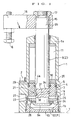
- FIG. 1 A first embodiment of a clamping apparatus according to the present invention is explained with reference to Figs. 1 to 7.
- a housing 1 of the clamping apparatus is fixed to an upper surface of a table (T) by a plurality of bolts 2 (only one of which is shown in this embodiment).
- An annular piston 4 is inserted into a guide bore 3 of the housing 1, to be oiltight and vertically movable, through a first packing 5.
- the piston 4 is prevented from rotating around an axis by engaging a vertical groove 6 of the piston 4 with a detent pin 7.
- a first chamber 11 is formed between a upper end wall (a first end wall) la of the housing 1 and the piston 4.
- a second chamber 12 is formed between a lower end wall (a second end wall) 1b of the housing 1 and the piston 4.
- the lower end wall 1b is constructed from a bottom wall of a screw cap 13. The screw cap 13 positions the detent pin 7.
- a clamp rod 9 is hermetically inserted into a through-hole 4a of the piston 4, to be oiltight, through a second packing 10.
- An input portion 9a for clamping provided at a lower end portion (a second end portion) of the clamp rod 9 is projected into the second chamber 12.
- An output portion 9b for clamping provided at an upper end portion (a first end portion) of the clamp rod 9 is projected upward of the upper end wall la of the housing 1.
- An arm 16 is fixed onto a tapered surface 15 of the output portion 9b through a nut 17.
- a push bolt 18 is brought into screw-thread engagement with a leading end of the arm 16 so as to be vertically adjustable.
- a clamping spring 20 consisting of a compression coil spring and mounted in the first chamber 11, it is moved upward against the clamping spring 20 by pressurized oil supplied to the second chamber 12.
- a converting mechanism 21 for converting a vertical movement of the piston 4 to a rotary movement of the clamp rod 9. A concrete structure of the converting mechanism 21 is described later.
- a stopper 23 for preventing the input portion 9a for clamping from moving upward.
- a thrust bearing 24 and an annular transmission plate 25 are interposed between the input portion 9a and the stopper 23.
- the transmission plate 25 is externally fitted onto the input portion 9a and supported axially movably by the peripheral wall of the second chamber 12.
- An upper side of the transmission plate 25 is communicated with a lower side thereof through a communication hole 26.
- Numeral 27 indicates a supply and discharge port of the pressurized oil.
- a breather passage 29 provided between the first chamber 11 and an outside of the housing 1 may be omitted.
- the breather passage 29 it is preferable to attach to the breather passage 29 a check valve (not shown) for prohibiting a flow from the outside of the housing 1 to the first chamber 11.
- the check valve can prohibit moisture, dust or the like foreign matters existing in the atmosphere from invading the first chamber 11 and therefore the piston 4 can be smoothly driven for a long period of time.
- pressurized oil having a pressure of about 50 to 140 kgf/cm 2 'about 5 to 14 MPa' in this embodiment
- the piston 4 and the clamp rod 9 are raised. Further, an allowable stroke (M) is formed below the input portion 9a for clamping.
- the back pressure keeps the input portion 9a for clamping pushed to the stopper 23 through the thrust bearing 24 and the transmission plate 25. Therefore, the clamp rod 9 is rotated by the converting mechanism 21 while the piston 4 is going down.
- the back pressure within the second chamber 12 constitutes a pushing means (P) at the time of clamp rotation.
- the pushing means (P) may further include a weak pushing spring in addition to the back pressure within the second chamber 12 or consist of only a pushing spring.
- FIG. 3 is an elevation view of an input portion 9c for rotation of the clamp rod 9.
- Fig. 4(A) is a partial plan view of the piston 4.
- Fig. 4(B) is a sectional view taken along a line B-B in Fig. 4(A) when seen in a direction indicated by arrows.
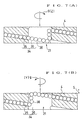
- Fig. 5 is a developed view of the piston 4 when the piston 4 is cut along a line V in Fig. 4(A) and the cut surface is seen from its inside.
- Fig. 6 is a developed view of the input portion 9c and corresponds to Fig. 5.
- the input portion 9c for rotation is provided with a rotary groove 30 concaved in the shape of an arc.
- the rotary groove 30 is composed of a first groove portion 31 formed spirally by about one pitch in an outer peripheral surface of the input portion 9c and a second groove portion 32 communicating an initial end of the first groove portion 31 with a terminal end thereof substantially in an axial direction.
- the piston 4 is provided with an actuating groove 34.
- the actuating groove 34 is composed of a rotation actuating groove portion 35 formed spirally in correspondence with the first groove portion 31 and a relief groove portion 36 formed so as to extend peripherally in correspondence with the second groove portion 32.
- the peripheral length of the relief groove portion 36 is'adjusted to correspond to a desired rotation angle ( ⁇ ) (about 90 degrees in this embodiment) of the clamp rod 9 as shown in Fig. 4(A).
- a number of steel rolling balls 38 are charged into a space between the rotary groove 30 and the actuating groove 34.
- the clamp rod 9 When rotating for retreating, the clamp rod 9 is switched over from the unclamping position (Y) of Fig. 2(B) and Fig. 7(B) to the retreated position (Z) of Fig. 2(A) and Fig. 7(A) according to the procedures substantially contrary to the above-mentioned ones.
- the converting mechanism 21 Since the converting mechanism 21 does not exert any excessive force on the balls 38, it is sufficient to provide only a single set of the rotary groove 30 and the actuating groove 34 and charge merely a small number of required balls, which results in the possibility of making the converting mechanism 21 compact and simple. Further, having a structure of rolling-ball type, the converting mechanism 21 suffers from only a small frictional resistance at the time of rotation. In consequence, it is possible to perform a smooth rotation and at the same time shorten a lead of the rotary groove 30. As a result, the rotation stroke (S) can be reduced, which in turn decreases a vertical space for installing the clamping apparatus.
- the first embodiment further presents the following advantages.
- the urging force of the clamping spring 20 produces the predetermined back pressure in the pressurized fluid within the second chamber 12.
- the input portion 9a for clamping can be pushed to the stopper 23 by utilizing that back pressure acting on the clamp rod 9. Therefore, the pushing spring may be removed from the pushing means (P).
- a spring force of the pushing spring constitutes a portion of a pushing force of the pushing means (P)
- the pushing 'means (P) becomes compact to result in the possibility of making the clamping apparatus smaller.
- annular transmission plate 25 interposed between the input portion 9a for clamping and the stopper' 23 is the annular transmission plate 25, into which the input portion 9a is inserted rotatably. Consequently, an outer diameter length of the input portion 9a can be decreased to result in the possibility of making the clamp rod 9 lighter.
- the annular transmission plate 25 is supported on the peripheral wall of the second chamber 12 axially movably, so that the input portion 9a for clamping can be guided by the peripheral wall of the second chamber 12 through the transmission plate 25.
- the clamp rod 9 can be guided with an improved accuracy to result in the possibility of conducting the clamping operation assuredly.
- the thrust bearing 24 is interposed between the annular transmission plate 25 and the input portion 9a for clamping. This arrangement can rotate the clamp rod 9 smoothly and assuredly to result in the possibility of making the converting mechanism 21 simple and compact.
- Figs. 8 and 9 each show a modification of the clamping apparatus and are partial views corresponding to Fig. 1.
- the members which function like those mentioned in the first embodiment are in principle designated by the same numerals.
- an actuation rod 42 is attached to the input portion 9a for clamping of the clamp rod 9 by a pin 41.
- the actuation rod 42 projects downward of the screw cap 13. It is possible to identify whether the clamping apparatus is in the clamping condition or in the retreated condition through detecting a height of a projected screw portion 43 of the actuation rod 42 by a limit switch or the like detectors.
- Fig. 9 The modification of Fig. 9 is created by modifying the clamping apparatus of Fig. 1 for a high-pressure use (where pressurized oil having a relatively high pressure of about 140 to 250 kgf/cm 2 'about 14 to 25 MPa' is supplied).
- a sleeve 45 for adapter is oiltightly fixed to the guide bore 3 of the housing 1.
- Numeral 46 designates a detent pin.
- the annular piston 4 is unrotatably inserted into the sleeve 45. More specifically, a projection 48 of a lower flange 47 of the piston 4 is fitted into a vertical groove 49 of the sleeve 45.
- the stopper 23 provided in the sleeve 45 receives the transmission plate 25.
- Fig. 10 shows a second embodiment of the clamping apparatus and corresponds to Fig. 1. Also in this second embodiment, the members which function like those mentioned in the first embodiment are in principle designated by the same numerals.
- the clamping apparatus shown in Fig. 10 fixes'an upper die 52 to an under surface of a slide 51 of a press machine. It is arranged in a posture vertically opposite to the first embodiment and has a structure of double-acting type.
- the pressurized oil has been discharged from the first chamber 11 and supplied to the second chamber 12.
- the clamp rod 9 is switched over to the retreated position (Z).
- the pressurized oil is discharged from the second chamber 12 and supplied to the first chamber 11.
- the clamp rod 9 is operated similarly as shown in Figs. 2(A), 2(B) and 2(C) and switched over to the clamping position (X) indicated by an alternate dash-and-two dots chain line.
- the clamp rod 9 can be strongly driven by the urging force of the clamping spring 20 in addition to the oil pressure of the first chamber 11. Even if the oil pressure of the first chamber 11 disappears for some reason, the urging force of the clamping spring 20 can keep the clamping condition.
- the pushing means (P) is composed of a pushing spring 55 attached within an upper portion of the clamp rod 9 and a back pressure produced within the second chamber 12 when the clamp rod 9 is rotated for clamping.
- Numeral 56 indicates a thrust bearing.
- the pushing means (P) may employ either of the pushing spring 55 and the back pressure within the second chamber 12.
- the second embodiment presents the following advantage.
- the pushing spring 55 for urging the clamp rod 9 toward the first end wall la. Accordingly, even if the back pressure produced within the second chamber 12 is small for some reason, the urging force of the pushing spring 55 can push the input portion 9a for clamping to the stopper 23 without failure and therefore rotate the clamp rod 9 assuredly.
- the fluid to be supplied to the first chamber 11 or the second chamber 12 may be other kinds of liquid or a gas such as air instead of the pressurized oil.
- the converting mechanism 21 may have a structure of either a combination of a spiral inclined groove and a cam fitted into the groove or a screw-thread fitting instead of the rolling-ball type.
Landscapes
- Engineering & Computer Science (AREA)
- Mechanical Engineering (AREA)
- Jigs For Machine Tools (AREA)
- Actuator (AREA)
- Clamps And Clips (AREA)
Claims (6)
- Drehklemmvorrichtung, umfassend:dadurch gekennzeichnet, daß:ein Gehäuse (1) mit einer ersten Stirnwand (1a), durch die ein Klemmstab (9) hervorsteht, und einer zweiten Stirnwand (1b);einen ringförmigen Kolben (4), der mit einem Durchgangsloch (4a) versehen ist und in das Gehäuse (1) so eingesetzt ist, daß er darin axial beweglich, aber drehungsfrei ist;eine erste Kammer (11), die zwischen der ersten Stirnwand (1a) und dem Kolben (4) ausgebildet ist;eine zweite Kammer (12), die zwischen der zweiten Stirnwand (1b) und dem Kolben (4) ausgebildet ist, wobei der Klemmstab (9) einen Antriebsteil (9a) zum Klemmen und einen Antriebsteil (9c) zur Drehung aufweist und hermetisch in das Durchgangsloch (4a) des Kolbens (4) eingesetzt ist, wobei der Antriebsteil (9a) zum Klemmen in die zweite Kammer (12) hineinragt; undeinen Umwandlungsmechanismus (21), der zwischen dem Antriebsteil (9c) zur Drehung und dem Kolben (4) vorgesehen ist, um eine axiale Bewegung des Kolbens (4) in eine Drehbewegung des Klemmstabs (9) umzuwandeln;eine Klemmfeder (20) in der ersten Kammer (11) zum Drücken des Kolbens (4) in Richtung der zweiten Stirnwand (1b) montiert ist;ein Zufuhr- und Ablaßkanal (27) für unter Druck stehendes Fluid zum Zuführen des unter Druck stehenden Fluids in die zweite Kammer (12) und zum Ablassen desselben aus dieser vorgesehen ist, um den Kolben (4) und den Klemmstab (9) anzuheben und abzusenken;ein Anschlag (23) die Bewegung des Antriebsteils (9a) zum Klemmen in Richtung der ersten Stirnwand (1a) während des Ausspannens begrenzt, so daß der Kolben (4) anschließend relativ zum Klemmstab (9) bewegt wird; wobei der Klemmstab (9) durch den Umwandlungsmechanismus (21) gedreht wird; undein Schubmittel (P) in der zweiten Kammer (12) zum Schieben des Antriebsteils (9a) zum Klemmen zum Anschlag (23) vorgesehen ist; so daß, wenn das unter Druck stehende Fluid aus der zweiten Kammer (12) durch den Kanal (27) abgelassen wird, die Druckkraft der Klemmfeder (20) den Kolben (4) in Richtung der zweiten Stirnwand (1b) drückt und der Umwandlungsmechanismus (21) den Klemmstab (9) dreht.
- Drehklemmvorrichtung nach Anspruch 1, wobei eine Druckkraft der Klemmfeder (20) einen vorbestimmten Gegendruck in dem unter Druck stehenden Fluid innerhalb der zweiten Kammer (12) erzeugt, wobei der Gegendruck, der auf den Klemmstab (9) wirkt, zumindest einen Teil einer Schubkraft des Schubmittels (P) bildet.
- Drehklemmvorrichtung nach Anspruch 1, wobei eine Druckfeder (55) zum Drücken des Klemmstabes (9) in Richtung der ersten Stirnwand (1a) vorgesehen ist, wobei eine Druckkraft der Druckfeder (55) zumindest einen Teil einer Schubkraft des Schubmittels (P) bildet.
- Drehklemmvorrichtung nach Anspruch 1, wobei eine ringförmige Übertragungsplatte (25) zwischen den Antriebsteil (9a) zum Klemmen und den Anschlag (23) eingefügt ist, wobei der Antriebsteil (9a) zum Klemmen drehbar in die Übertragungsplatte (25) eingesetzt ist.
- Drehklemmvorrichtung nach Anspruch 4, wobei die ringförmige Übertragungsplatte (25) durch eine Umfangswand der zweiten Kammer (12) axial beweglich abgestützt wird.
- Drehklemmvorrichtung nach Anspruch 4, wobei ein Axiallager (24) zwischen die Übertragungsplatte (25) und den Antriebsteil (9a) zum Klemmen eingefügt ist.
Applications Claiming Priority (3)
| Application Number | Priority Date | Filing Date | Title |
|---|---|---|---|
| JP293486/96 | 1996-11-06 | ||
| JP8293486A JPH10141324A (ja) | 1996-11-06 | 1996-11-06 | 旋回式クランプ装置 |
| JP29348696 | 1996-11-06 |
Publications (2)
| Publication Number | Publication Date |
|---|---|
| EP0841124A1 EP0841124A1 (de) | 1998-05-13 |
| EP0841124B1 true EP0841124B1 (de) | 2001-06-20 |
Family
ID=17795370
Family Applications (1)
| Application Number | Title | Priority Date | Filing Date |
|---|---|---|---|
| EP97118555A Expired - Lifetime EP0841124B1 (de) | 1996-11-06 | 1997-10-24 | Schwenkspanner |
Country Status (6)
| Country | Link |
|---|---|
| US (1) | US6113086A (de) |
| EP (1) | EP0841124B1 (de) |
| JP (1) | JPH10141324A (de) |
| KR (1) | KR19980041970A (de) |
| DE (1) | DE69705286T2 (de) |
| TW (1) | TW405487U (de) |
Families Citing this family (32)
| Publication number | Priority date | Publication date | Assignee | Title |
|---|---|---|---|---|
| GB2344547B (en) * | 1998-11-14 | 2002-12-18 | Aldridge Piling Equipment | Actuator apparatus |
| ITMI20010750A1 (it) * | 2001-04-06 | 2002-10-06 | Uniteam S R L | Dispositivo per il posizionamento ed il bloccaggio dei pezzi su macchine per la lavorazione del legno e relativa macchina |
| JP2003089027A (ja) * | 2001-09-14 | 2003-03-25 | Pascal Corp | ツイスト式クランプ装置 |
| JP3621082B2 (ja) * | 2001-11-13 | 2005-02-16 | 株式会社コスメック | 旋回式クランプ |
| JP4038108B2 (ja) * | 2001-11-13 | 2008-01-23 | 株式会社コスメック | 旋回式クランプ |
| TW579316B (en) | 2001-11-13 | 2004-03-11 | Kosmek Ltd | Rotary clamp |
| DE10158844A1 (de) * | 2001-11-27 | 2003-06-12 | Herbert Haenchen Gmbh & Co Kg | Klemmvorrichtung und Stelleinrichtung |
| JP4094340B2 (ja) * | 2002-02-13 | 2008-06-04 | 株式会社コスメック | クランプの動作検出装置 |
| TW544361B (en) | 2002-04-03 | 2003-08-01 | Kosmek Kk | Rotary clamp |
| US6929254B2 (en) * | 2002-06-24 | 2005-08-16 | Phd, Inc. | Swing-arm clamp |
| US6902160B1 (en) * | 2003-01-22 | 2005-06-07 | Zaytran, Inc. | Locating pin with integrated clamp |
| US6931980B1 (en) * | 2003-03-21 | 2005-08-23 | Zaytran, Inc. | Pneumatic device with cushioning mechanism |
| FR2864603B1 (fr) * | 2003-12-30 | 2006-03-17 | Fmc Technologies Sa | Coupleur a transmission directe du mouvement de rotation d'une vis d'actionnement a une machoire entrainee en translation par celle-ci |
| CN101142053A (zh) * | 2005-03-18 | 2008-03-12 | 克斯美库股份有限公司 | 螺纹啮合型夹紧装置、夹紧系统及流体压力致动器 |
| WO2007043183A1 (ja) * | 2005-10-14 | 2007-04-19 | Pascal Engineering Corporation | スイング式クランプ装置 |
| JP2007187182A (ja) * | 2006-01-11 | 2007-07-26 | Hokoku Kogyo Co Ltd | トルクアクチュエータ |
| EP2130643A4 (de) * | 2007-02-23 | 2013-04-10 | Kosmek Ltd | Vorrichtung zur erfassung der betätigung einer klemme |
| US7806384B2 (en) * | 2007-09-11 | 2010-10-05 | Suspa Incorporated | Lift with low profile rotatable coupling |
| US7637479B2 (en) * | 2008-04-24 | 2009-12-29 | Emhiser Research Limited | Hydraulic pumping cylinder and method of pumping hydraulic fluid |
| CN103185045B (zh) * | 2011-12-29 | 2015-08-12 | 富泰华工业(深圳)有限公司 | 气缸 |
| CN103495878A (zh) * | 2013-09-29 | 2014-01-08 | 大连机床(数控)股份有限公司 | 带旋转功能的夹具 |
| JP5734398B2 (ja) * | 2013-11-28 | 2015-06-17 | ファナック株式会社 | 物体を受け部に固定するための物体固定装置、工作機械、ロボット、および物体を受け部に固定する方法 |
| US10217478B2 (en) * | 2015-07-10 | 2019-02-26 | Seagate Technology Llc | Linear and rotational adjustment systems |
| CN205583269U (zh) * | 2016-04-13 | 2016-09-14 | 东莞市伟宏五金塑胶制品有限公司 | 旋转支架及桌板组件 |
| JP6759112B2 (ja) * | 2017-01-06 | 2020-09-23 | 日本スピンドル製造株式会社 | 回転塑性加工装置 |
| CN107052857B (zh) * | 2017-02-10 | 2023-04-18 | 广东机电职业技术学院 | 自动卸料与清理的分度夹具 |
| EP3363992A1 (de) * | 2017-02-16 | 2018-08-22 | General Electric Company | Absteckwerkzeug |
| US11110560B2 (en) * | 2017-04-05 | 2021-09-07 | Kosmek Ltd. | Rotary clamp |
| EP4015140B1 (de) * | 2020-03-25 | 2026-03-11 | Chengdu Aircraft Industrial (Group) Co., Ltd. | Klemmvorrichtung und bearbeitungsverfahren |
| CN112192273B (zh) * | 2020-10-09 | 2022-11-15 | 温州弘球机械有限公司 | 阀芯全自动装夹设备 |
| CN113770762B (zh) * | 2021-01-26 | 2023-10-20 | 辉腾交通器材(安徽)有限公司 | 一种摩托车活塞环加工用固定夹持设备 |
| CN114654393B (zh) * | 2022-03-07 | 2023-08-18 | 常州荣玖机械有限公司 | 一种用于拼装圆形膜片式夹紧气缸的快速工装装置 |
Family Cites Families (10)
| Publication number | Priority date | Publication date | Assignee | Title |
|---|---|---|---|---|
| US3572216A (en) * | 1969-04-23 | 1971-03-23 | Applied Power Ind Inc | Fluid force applying device |
| JPS4941550A (de) * | 1972-08-26 | 1974-04-18 | ||
| GB1435027A (en) * | 1973-11-26 | 1976-05-12 | Spenklin Ltd | Power-operated work clamping devices |
| US4265434A (en) * | 1979-08-08 | 1981-05-05 | Barry Wright Corporation | Hydraulic clamp |
| DE3031368C2 (de) * | 1980-08-20 | 1982-10-14 | Maschinenfabrik Hilma Gmbh, 5912 Hilchenbach | Schwenkspanner |
| JPS57138550A (en) * | 1981-02-20 | 1982-08-26 | Aioi Seiki Kk | Turning disengageable type clamping apparatus of processing machine |
| US4560152A (en) * | 1984-04-27 | 1985-12-24 | Applied Power Inc. | Swing clamp |
| JP2741268B2 (ja) * | 1989-12-29 | 1998-04-15 | 株式会社コスメック | クランプ具旋回・直動式油圧クランプ |
| JPH0470163U (de) * | 1990-09-17 | 1992-06-22 | ||
| US5192058A (en) * | 1992-01-02 | 1993-03-09 | Vektek, Inc. | Swing clamp |
-
1996
- 1996-11-06 JP JP8293486A patent/JPH10141324A/ja active Pending
-
1997
- 1997-10-14 TW TW088215352U patent/TW405487U/zh not_active IP Right Cessation
- 1997-10-24 EP EP97118555A patent/EP0841124B1/de not_active Expired - Lifetime
- 1997-10-24 DE DE69705286T patent/DE69705286T2/de not_active Expired - Fee Related
- 1997-10-28 KR KR1019970055671A patent/KR19980041970A/ko not_active Abandoned
- 1997-10-31 US US08/962,259 patent/US6113086A/en not_active Expired - Fee Related
Also Published As
| Publication number | Publication date |
|---|---|
| DE69705286D1 (de) | 2001-07-26 |
| JPH10141324A (ja) | 1998-05-26 |
| US6113086A (en) | 2000-09-05 |
| KR19980041970A (ko) | 1998-08-17 |
| EP0841124A1 (de) | 1998-05-13 |
| TW405487U (en) | 2000-09-11 |
| DE69705286T2 (de) | 2002-05-16 |
Similar Documents
| Publication | Publication Date | Title |
|---|---|---|
| US6113086A (en) | Rotary clamping apparatus | |
| EP1310331B1 (de) | Schwenkende Spannvorrichtung | |
| EP0819501B1 (de) | Schwenkspanner | |
| KR100921292B1 (ko) | 클램프의 동작검출장치 | |
| US6663093B2 (en) | Rotary clamp | |
| KR100961304B1 (ko) | 스프링 로크식 클램프 장치 | |
| EP0893624B1 (de) | Antriebsvorrichtung | |
| US6666440B2 (en) | Rotary clamp | |
| EP0802330B1 (de) | Federspannzylinder | |
| KR20190109462A (ko) | 선회식 클램프 | |
| JP4094339B2 (ja) | 旋回式クランプ | |
| JPH1080833A (ja) | 旋回式クランプ装置 | |
| JP2005329525A (ja) | 旋回式クランプ | |
| US20210164499A1 (en) | Cylinder device | |
| JP2026078900A (ja) | 流体給排装置 | |
| JP2003039262A (ja) | スイングクランプ |
Legal Events
| Date | Code | Title | Description |
|---|---|---|---|
| PUAI | Public reference made under article 153(3) epc to a published international application that has entered the european phase |
Free format text: ORIGINAL CODE: 0009012 |
|
| AK | Designated contracting states |
Kind code of ref document: A1 Designated state(s): DE FR GB IT |
|
| AX | Request for extension of the european patent |
Free format text: AL;LT;LV;RO;SI |
|
| 17P | Request for examination filed |
Effective date: 19980909 |
|
| AKX | Designation fees paid |
Free format text: DE FR GB IT |
|
| RBV | Designated contracting states (corrected) |
Designated state(s): DE FR GB IT |
|
| 17Q | First examination report despatched |
Effective date: 19990105 |
|
| GRAG | Despatch of communication of intention to grant |
Free format text: ORIGINAL CODE: EPIDOS AGRA |
|
| GRAG | Despatch of communication of intention to grant |
Free format text: ORIGINAL CODE: EPIDOS AGRA |
|
| GRAG | Despatch of communication of intention to grant |
Free format text: ORIGINAL CODE: EPIDOS AGRA |
|
| GRAH | Despatch of communication of intention to grant a patent |
Free format text: ORIGINAL CODE: EPIDOS IGRA |
|
| GRAH | Despatch of communication of intention to grant a patent |
Free format text: ORIGINAL CODE: EPIDOS IGRA |
|
| GRAA | (expected) grant |
Free format text: ORIGINAL CODE: 0009210 |
|
| AK | Designated contracting states |
Kind code of ref document: B1 Designated state(s): DE FR GB IT |
|
| REF | Corresponds to: |
Ref document number: 69705286 Country of ref document: DE Date of ref document: 20010726 |
|
| ET | Fr: translation filed | ||
| ITF | It: translation for a ep patent filed | ||
| REG | Reference to a national code |
Ref country code: GB Ref legal event code: IF02 |
|
| PLBE | No opposition filed within time limit |
Free format text: ORIGINAL CODE: 0009261 |
|
| STAA | Information on the status of an ep patent application or granted ep patent |
Free format text: STATUS: NO OPPOSITION FILED WITHIN TIME LIMIT |
|
| 26N | No opposition filed | ||
| PGFP | Annual fee paid to national office [announced via postgrant information from national office to epo] |
Ref country code: GB Payment date: 20021014 Year of fee payment: 6 |
|
| PGFP | Annual fee paid to national office [announced via postgrant information from national office to epo] |
Ref country code: FR Payment date: 20021023 Year of fee payment: 6 |
|
| PGFP | Annual fee paid to national office [announced via postgrant information from national office to epo] |
Ref country code: DE Payment date: 20021031 Year of fee payment: 6 |
|
| PG25 | Lapsed in a contracting state [announced via postgrant information from national office to epo] |
Ref country code: GB Free format text: LAPSE BECAUSE OF NON-PAYMENT OF DUE FEES Effective date: 20031024 |
|
| PG25 | Lapsed in a contracting state [announced via postgrant information from national office to epo] |
Ref country code: DE Free format text: LAPSE BECAUSE OF NON-PAYMENT OF DUE FEES Effective date: 20040501 |
|
| GBPC | Gb: european patent ceased through non-payment of renewal fee |
Effective date: 20031024 |
|
| PG25 | Lapsed in a contracting state [announced via postgrant information from national office to epo] |
Ref country code: FR Free format text: LAPSE BECAUSE OF NON-PAYMENT OF DUE FEES Effective date: 20040630 |
|
| REG | Reference to a national code |
Ref country code: FR Ref legal event code: ST |
|
| PG25 | Lapsed in a contracting state [announced via postgrant information from national office to epo] |
Ref country code: IT Free format text: LAPSE BECAUSE OF NON-PAYMENT OF DUE FEES Effective date: 20051024 |