EP0840059A2 - Lampe scialytique - Google Patents
Lampe scialytique Download PDFInfo
- Publication number
- EP0840059A2 EP0840059A2 EP97116551A EP97116551A EP0840059A2 EP 0840059 A2 EP0840059 A2 EP 0840059A2 EP 97116551 A EP97116551 A EP 97116551A EP 97116551 A EP97116551 A EP 97116551A EP 0840059 A2 EP0840059 A2 EP 0840059A2
- Authority
- EP
- European Patent Office
- Prior art keywords
- light
- hollow reflector
- field
- environment
- main
- Prior art date
- Legal status (The legal status is an assumption and is not a legal conclusion. Google has not performed a legal analysis and makes no representation as to the accuracy of the status listed.)
- Withdrawn
Links
- 206010052428 Wound Diseases 0.000 description 4
- 208000027418 Wounds and injury Diseases 0.000 description 3
- 238000010521 absorption reaction Methods 0.000 description 2
- 208000003464 asthenopia Diseases 0.000 description 2
- 238000010586 diagram Methods 0.000 description 2
- 230000000694 effects Effects 0.000 description 2
- 230000005855 radiation Effects 0.000 description 2
- 230000000740 bleeding effect Effects 0.000 description 1
- 239000012141 concentrate Substances 0.000 description 1
- 230000003247 decreasing effect Effects 0.000 description 1
- 239000011521 glass Substances 0.000 description 1
- 238000005286 illumination Methods 0.000 description 1
- 235000013372 meat Nutrition 0.000 description 1
- 230000002028 premature Effects 0.000 description 1
Images

Classifications
-
- F—MECHANICAL ENGINEERING; LIGHTING; HEATING; WEAPONS; BLASTING
- F21—LIGHTING
- F21V—FUNCTIONAL FEATURES OR DETAILS OF LIGHTING DEVICES OR SYSTEMS THEREOF; STRUCTURAL COMBINATIONS OF LIGHTING DEVICES WITH OTHER ARTICLES, NOT OTHERWISE PROVIDED FOR
- F21V7/00—Reflectors for light sources
- F21V7/22—Reflectors for light sources characterised by materials, surface treatments or coatings, e.g. dichroic reflectors
-
- F—MECHANICAL ENGINEERING; LIGHTING; HEATING; WEAPONS; BLASTING
- F21—LIGHTING
- F21W—INDEXING SCHEME ASSOCIATED WITH SUBCLASSES F21K, F21L, F21S and F21V, RELATING TO USES OR APPLICATIONS OF LIGHTING DEVICES OR SYSTEMS
- F21W2131/00—Use or application of lighting devices or systems not provided for in codes F21W2102/00-F21W2121/00
- F21W2131/20—Lighting for medical use
- F21W2131/205—Lighting for medical use for operating theatres
-
- Y—GENERAL TAGGING OF NEW TECHNOLOGICAL DEVELOPMENTS; GENERAL TAGGING OF CROSS-SECTIONAL TECHNOLOGIES SPANNING OVER SEVERAL SECTIONS OF THE IPC; TECHNICAL SUBJECTS COVERED BY FORMER USPC CROSS-REFERENCE ART COLLECTIONS [XRACs] AND DIGESTS
- Y10—TECHNICAL SUBJECTS COVERED BY FORMER USPC
- Y10S—TECHNICAL SUBJECTS COVERED BY FORMER USPC CROSS-REFERENCE ART COLLECTIONS [XRACs] AND DIGESTS
- Y10S362/00—Illumination
- Y10S362/804—Surgical or dental spotlight
Definitions
- the invention relates to an operating light according to the preamble of claim 1.
- Such lights are e.g. known from German patents 32 43 709 and 32 43 710.
- a suitable design of the hollow reflector ensures that the area of a medical operation is illuminated as brightly as possible and free of shadows.
- a ring-shaped additional reflector has been attached below the lamp, which can be moved into the hollow reflector in order to allow part of the lamp light to strike the operating field more steeply (EP 0 468 287 B1).
- auxiliary ring reflectors have already been provided within the main hollow reflector for the purpose of reducing the size of the hollow reflector while maintaining the illuminance (DE-OS 41 40 325).
- the purpose of the special measures on known hollow ring reflectors is in each case to obtain a light field which is illuminated as uniformly as possible and has a diameter of approximately 15 to 30 cm.
- ever brighter lamps and better reflecting hollow reflectors have been used, since bleeding meat in an open wound absorbs a large part of the incident light and reflects only a small part, so that the surgeon can only properly observe the operation when the illuminance is sufficiently high .
- illuminance levels of up to 150,000 lux are achieved with surgical lights, but this results in an unbearably bright and glaring light on a light background, which quickly tires the eyes. Since the room light available in an operating room has an illuminance of approximately Should generate 1000 lux, the ratio of the maximum illuminance of the surgical light to that of the room lighting is 150: 1. This leads to severe eye fatigue.
- the aim of the present invention is to provide an operating light of the type mentioned at the outset, which can work with the highest illuminance levels without tiring the operator's eyes.
- the idea of the invention is therefore to be seen in the fact that beyond the weak light environment that occurs due to the unavoidable scattering effects and imperfections of the reflectors, the aim is to create a consciously generated light environment that is directly adjacent to the main light field and that is in such a ratio with regard to its illuminance
- the illuminance of the main light field means that fatigue in the eyes of the surgeon is counteracted, at least to a considerable extent. In this way it is possible to achieve a gradation between the maximum illuminance in the main light field and in the light environment of only about 30: 1.
- the difference is the reflected light of the wound that is actually detected by the eye and the environment due to the measures according to the invention very low. This prevents premature eye fatigue. If you had a system with a similarly high peak illuminance and a not gradually decreasing illuminance in the surroundings, so the strong absorption of the wound and the low absorption of the surroundings would result in the effect of a dark hole in the middle. This is undesirable. According to the invention, it is important that the drop from the light intensity in the main light field to the light environment takes place over the shortest possible distance, which should be a few cm.
- the illuminance should be as constant as possible and decrease as little as possible radially outwards.
- the outside diameter of the light environment according to the invention is about 50 to 90 cm, but should be at least 40 cm.
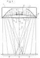
- a hollow ring reflector 14 with a central axis 23 is arranged in the downwardly open housing 11 of an operating light according to the invention, which is essentially parabolic or partially spherical and has a light exit opening 12 at the bottom, which is open through an opening Side of the housing provided translucent pane 18 is covered, for example, from cathedral glass.
- the disk 18 has an opening 19 in the center in which a plate arrangement 20 is fastened with a handle 21 for pivoting the housing 11.
- a lamp 13 is fastened above the plate arrangement 20 in the region of the focal point of the hollow reflector 14 and is surrounded by a circular cylindrical filter 22 which absorbs primarily IR radiation and which detects all of the light radiation reaching the hollow reflector 14 and can also filter out UV components.
- the hollow reflector 14 is parabolic or part-spherical in most of its surface in order to concentrate the light emitted by the lamp 13 on an operating field 24 in a main light field 15 arranged at a distance below the housing 11 and around the central axis 23 of the housing 11
- the lower region of the hollow reflector 14 is slightly convexly curved and finally widened conically outwards in such a way that an annular region 14 'concentric with the central axis 23 is formed in the lower end region of the hollow reflector 14, which is there incident light from the lamp 13 specifically directed into a light environment 17 which surrounds the main light field 15 radially adjacent.
- the design and size of the annular area 14 ' are selected such that the light environment 17 is also uniformly illuminated, but with a significantly reduced illuminance in the ratio of e.g. 1:30 in relation to the illuminance in the main light field 15.
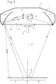
- FIG. 3 shows the light distribution that can be achieved by the surgical light described, the dependence the illuminance in kilo-lux from the radius of the main light field 15 or the concentric light environment 17 is shown schematically.
- This diagram shows that the maximum illuminance in the area of the central axis 23 of the housing 11 is over 100 klx and then drops to a value well below 10 klx up to an area with a radius of approximately 28 cm, which is the illuminance in the light environment 17 corresponds. From this radius onwards, the illuminance remains approximately constant up to a diameter of approx. 50 cm or only drops slightly here, in order to finally change to the illuminance R of the room lighting, which is approx. 1 klx, at a diameter of approx. 60 cm.
- the illuminance b in the light environment 17 is approximately 5 to 30 klx.
- the ring hollow reflector 14 is parabolic or partially spherical up to its largest diameter.
- an auxiliary ring reflector 16 is arranged within the upper central opening of the hollow reflector 14, which has an inclination and / or curvature such that the light of the lamp 13 striking it via a part of the main hollow reflector 14 into the light environment 17 and the main light field 15 is directed so that the overlap in the main light field 15, even when the working distance between the main light field 15 and the light environment 17 changes, can never result in an illumination gap.
Landscapes
- Engineering & Computer Science (AREA)
- General Engineering & Computer Science (AREA)
- Non-Portable Lighting Devices Or Systems Thereof (AREA)
Applications Claiming Priority (2)
| Application Number | Priority Date | Filing Date | Title |
|---|---|---|---|
| DE19644959 | 1996-10-29 | ||
| DE19644959A DE19644959A1 (de) | 1996-10-29 | 1996-10-29 | Operationsleuchte |
Publications (2)
| Publication Number | Publication Date |
|---|---|
| EP0840059A2 true EP0840059A2 (fr) | 1998-05-06 |
| EP0840059A3 EP0840059A3 (fr) | 1999-09-08 |
Family
ID=7810327
Family Applications (1)
| Application Number | Title | Priority Date | Filing Date |
|---|---|---|---|
| EP97116551A Withdrawn EP0840059A3 (fr) | 1996-10-29 | 1997-09-23 | Lampe scialytique |
Country Status (3)
| Country | Link |
|---|---|
| US (1) | US6132067A (fr) |
| EP (1) | EP0840059A3 (fr) |
| DE (1) | DE19644959A1 (fr) |
Cited By (1)
| Publication number | Priority date | Publication date | Assignee | Title |
|---|---|---|---|---|
| CN103807625A (zh) * | 2012-11-12 | 2014-05-21 | 南昌迈柯尔医疗器械有限公司 | 一种整体反射led灯头装置及利用该装置的无影灯 |
Families Citing this family (5)
| Publication number | Priority date | Publication date | Assignee | Title |
|---|---|---|---|---|
| TW563264B (en) * | 2002-10-11 | 2003-11-21 | Highlink Technology Corp | Base of optoelectronic device |
| US6874914B2 (en) * | 2002-12-04 | 2005-04-05 | Sage Technology, Llc | Adjustable lighting system |
| US8016470B2 (en) * | 2007-10-05 | 2011-09-13 | Dental Equipment, Llc | LED-based dental exam lamp with variable chromaticity |
| CN101451678A (zh) * | 2007-12-06 | 2009-06-10 | 富士迈半导体精密工业(上海)有限公司 | 固态照明装置 |
| EP3812649A4 (fr) * | 2018-06-22 | 2021-06-02 | Nanjing Mindray Bio-Medical Electronics Co., Ltd. | Lampe chirurgicale |
Citations (4)
| Publication number | Priority date | Publication date | Assignee | Title |
|---|---|---|---|---|
| DE3243709C2 (fr) | 1982-11-25 | 1990-10-31 | Delma, Elektro- Und Medizinische Apparatebaugesellschaft Mbh, 7200 Tuttlingen, De | |
| DE3243710C2 (fr) | 1982-11-25 | 1991-12-12 | Delma, Elektro- Und Medizinische Apparatebaugesellschaft Mbh, 7200 Tuttlingen, De | |
| DE4140325A1 (de) | 1991-12-06 | 1993-06-09 | Delma Elektro- Und Medizinische Apparatebau Gmbh, 7200 Tuttlingen, De | Operationsleuchte |
| EP0468287B1 (fr) | 1990-07-23 | 1994-05-18 | DELMA ELEKTRO-UND MEDIZINISCHE APPARATEBAU GESELLSCHAFT mbH | Lampe scialytique |
Family Cites Families (19)
| Publication number | Priority date | Publication date | Assignee | Title |
|---|---|---|---|---|
| US1286535A (en) * | 1917-12-19 | 1918-12-03 | Wesley E Cochran | Lighting-fixture. |
| DE483950C (de) * | 1926-02-16 | 1929-10-08 | Koerting & Mathiesen A G | Kohlen-Bogenlampe fuer therapeutische Zwecke |
| US2126650A (en) * | 1935-09-09 | 1938-08-09 | Superlux Corp | Lighting device |
| DE849832C (de) * | 1950-08-26 | 1952-09-18 | Hueper & Schmidt K G | Schlagschattenfreier Reflektor, insbesondere fuer Operationszwecke |
| FR1045467A (fr) * | 1951-11-26 | 1953-11-26 | Dispositif d'éclairage notamment pour champ opératoire | |
| FR66975E (fr) * | 1954-10-02 | 1957-11-04 | Dispositif d'éclairage notamment pour champ opératoire | |
| US4280167A (en) * | 1979-09-13 | 1981-07-21 | Ellett Edwin W | Operating room surgical lamp |
| US4447865A (en) * | 1982-05-13 | 1984-05-08 | General Electric Company | Reflector lamp |
| DE3238876C2 (de) * | 1982-10-18 | 1985-01-17 | Franz Sill Gmbh, 1000 Berlin | Reflektor für eine mit einer Hochdruckentladungslampe versehene Decken-Einbauleuchte |
| US4651257A (en) * | 1985-07-15 | 1987-03-17 | American Sterilizer Company | Multiple source lighting fixture |
| US4617619A (en) * | 1985-10-02 | 1986-10-14 | American Sterilizer Company | Reflector for multiple source lighting fixture |
| DE3605226A1 (de) * | 1986-02-19 | 1987-08-27 | Daume & Jordan Gmbh & Co Kg | Blendungsfreie leuchte mit streifenfoermigem abblendreflektor |
| DE3638669A1 (de) * | 1986-11-12 | 1988-05-26 | Auer Sog Glaswerke Gmbh | Reflektor fuer zahnaerztliche und chirurgische operationsleuchten |
| US5001616A (en) * | 1990-03-16 | 1991-03-19 | American Sterilizer Company | Optical system for lighting fixture |
| US5067064A (en) * | 1990-03-16 | 1991-11-19 | American Sterilizer Company | Pattern change mechanism |
| DE4033625A1 (de) * | 1990-10-23 | 1992-04-30 | Bieroth Heinz | Beleuchtung eines operationstisches |
| US5373430A (en) * | 1992-04-16 | 1994-12-13 | Mcdermott; Kevin | Wide angle beam pattern lamp |
| US5582478A (en) * | 1993-10-29 | 1996-12-10 | Ambrosino; Donald J. | Food covering system with illuminating and/or moving decorations |
| US5791768A (en) * | 1997-04-17 | 1998-08-11 | Stingray Lighting, Inc. | Dual reflector lighting system |
-
1996
- 1996-10-29 DE DE19644959A patent/DE19644959A1/de not_active Withdrawn
-
1997
- 1997-09-23 EP EP97116551A patent/EP0840059A3/fr not_active Withdrawn
- 1997-10-28 US US08/958,807 patent/US6132067A/en not_active Expired - Fee Related
Patent Citations (4)
| Publication number | Priority date | Publication date | Assignee | Title |
|---|---|---|---|---|
| DE3243709C2 (fr) | 1982-11-25 | 1990-10-31 | Delma, Elektro- Und Medizinische Apparatebaugesellschaft Mbh, 7200 Tuttlingen, De | |
| DE3243710C2 (fr) | 1982-11-25 | 1991-12-12 | Delma, Elektro- Und Medizinische Apparatebaugesellschaft Mbh, 7200 Tuttlingen, De | |
| EP0468287B1 (fr) | 1990-07-23 | 1994-05-18 | DELMA ELEKTRO-UND MEDIZINISCHE APPARATEBAU GESELLSCHAFT mbH | Lampe scialytique |
| DE4140325A1 (de) | 1991-12-06 | 1993-06-09 | Delma Elektro- Und Medizinische Apparatebau Gmbh, 7200 Tuttlingen, De | Operationsleuchte |
Cited By (1)
| Publication number | Priority date | Publication date | Assignee | Title |
|---|---|---|---|---|
| CN103807625A (zh) * | 2012-11-12 | 2014-05-21 | 南昌迈柯尔医疗器械有限公司 | 一种整体反射led灯头装置及利用该装置的无影灯 |
Also Published As
| Publication number | Publication date |
|---|---|
| US6132067A (en) | 2000-10-17 |
| DE19644959A1 (de) | 1998-04-30 |
| EP0840059A3 (fr) | 1999-09-08 |
Similar Documents
| Publication | Publication Date | Title |
|---|---|---|
| EP0468287B1 (fr) | Lampe scialytique | |
| CH671455A5 (fr) | ||
| EP0982534A2 (fr) | Lampe pour former un champ d'éclairage sans ombres | |
| EP0191264B2 (fr) | Dispositif anti-éblouissant pour appareils d'éclairage de grande dimension | |
| DE4140325C2 (de) | Operationsleuchte | |
| EP0840059A2 (fr) | Lampe scialytique | |
| DE1259747B (de) | Anordnung zum Verhindern von Phantomlicht in einer Signallichtanlage fuer Automobileod. dgl. | |
| DE19758551B4 (de) | Fahrradrückleuchte mit mindestens zwei Leuchtdioden | |
| DE561639C (de) | Elektrische Doppelfadengluehlampe fuer Scheinwerfer an Kraftfahrzeugen | |
| DE4312889B4 (de) | Vorwiegend direkt strahlende Leuchte mit einem abgehängten Lichtleitkörper | |
| EP1045195B1 (fr) | Luminaire | |
| DE10139002A1 (de) | Einbauleuchte | |
| DE3827834A1 (de) | Fresnellinse | |
| DE2901320A1 (de) | Beleuchtungseinrichtung | |
| EP1072840B1 (fr) | Luminaire | |
| DE102023103126B4 (de) | Licht streuender Aufsatz für eine Leuchte und Leuchte | |
| DE1183873B (de) | Scheinwerfer fuer Farbsignale, insbesondere fuer Verkehrsregelung | |
| EP1848919B1 (fr) | Dispositif d'eclairage | |
| DE3807584A1 (de) | Operationsleuchte | |
| DE2217421A1 (de) | Geraet zur buendelung von strahlen | |
| EP0994294A2 (fr) | Dispositif d'éclairage pour la fixation sur une première paroi définissant une surface d'émission de lumière | |
| DE202023101390U1 (de) | Licht streuender Aufsatz für eine Leuchte und Leuchte | |
| DE2219416A1 (de) | Pollerleuchte | |
| DE2731671A1 (de) | Deckenleuchte | |
| DE861087C (de) | Reflektor-System fuer Leuchtgeraete |
Legal Events
| Date | Code | Title | Description |
|---|---|---|---|
| PUAI | Public reference made under article 153(3) epc to a published international application that has entered the european phase |
Free format text: ORIGINAL CODE: 0009012 |
|
| AK | Designated contracting states |
Kind code of ref document: A2 Designated state(s): AT BE CH DE DK ES FI FR GB GR IE IT LI LU MC NL PT SE |
|
| AX | Request for extension of the european patent |
Free format text: AL;LT;LV;RO;SI |
|
| ITCL | It: translation for ep claims filed |
Representative=s name: DALLA ROSA ADRIANO |
|
| PUAL | Search report despatched |
Free format text: ORIGINAL CODE: 0009013 |
|
| AK | Designated contracting states |
Kind code of ref document: A3 Designated state(s): AT BE CH DE DK ES FI FR GB GR IE IT LI LU MC NL PT SE |
|
| AX | Request for extension of the european patent |
Free format text: AL;LT;LV;RO;SI |
|
| AKX | Designation fees paid | ||
| REG | Reference to a national code |
Ref country code: DE Ref legal event code: 8566 |
|
| STAA | Information on the status of an ep patent application or granted ep patent |
Free format text: STATUS: THE APPLICATION IS DEEMED TO BE WITHDRAWN |
|
| 18D | Application deemed to be withdrawn |
Effective date: 20000309 |