EP0840059A2 - Operating lamp - Google Patents
Operating lamp Download PDFInfo
- Publication number
- EP0840059A2 EP0840059A2 EP97116551A EP97116551A EP0840059A2 EP 0840059 A2 EP0840059 A2 EP 0840059A2 EP 97116551 A EP97116551 A EP 97116551A EP 97116551 A EP97116551 A EP 97116551A EP 0840059 A2 EP0840059 A2 EP 0840059A2
- Authority
- EP
- European Patent Office
- Prior art keywords
- light
- hollow reflector
- field
- environment
- main
- Prior art date
- Legal status (The legal status is an assumption and is not a legal conclusion. Google has not performed a legal analysis and makes no representation as to the accuracy of the status listed.)
- Withdrawn
Links
- 206010052428 Wound Diseases 0.000 description 4
- 208000027418 Wounds and injury Diseases 0.000 description 3
- 238000010521 absorption reaction Methods 0.000 description 2
- 208000003464 asthenopia Diseases 0.000 description 2
- 238000010586 diagram Methods 0.000 description 2
- 230000000694 effects Effects 0.000 description 2
- 230000005855 radiation Effects 0.000 description 2
- 230000000740 bleeding effect Effects 0.000 description 1
- 239000012141 concentrate Substances 0.000 description 1
- 230000003247 decreasing effect Effects 0.000 description 1
- 239000011521 glass Substances 0.000 description 1
- 238000005286 illumination Methods 0.000 description 1
- 235000013372 meat Nutrition 0.000 description 1
- 230000002028 premature Effects 0.000 description 1
Images

Classifications
-
- F—MECHANICAL ENGINEERING; LIGHTING; HEATING; WEAPONS; BLASTING
- F21—LIGHTING
- F21V—FUNCTIONAL FEATURES OR DETAILS OF LIGHTING DEVICES OR SYSTEMS THEREOF; STRUCTURAL COMBINATIONS OF LIGHTING DEVICES WITH OTHER ARTICLES, NOT OTHERWISE PROVIDED FOR
- F21V7/00—Reflectors for light sources
- F21V7/22—Reflectors for light sources characterised by materials, surface treatments or coatings, e.g. dichroic reflectors
-
- F—MECHANICAL ENGINEERING; LIGHTING; HEATING; WEAPONS; BLASTING
- F21—LIGHTING
- F21W—INDEXING SCHEME ASSOCIATED WITH SUBCLASSES F21K, F21L, F21S and F21V, RELATING TO USES OR APPLICATIONS OF LIGHTING DEVICES OR SYSTEMS
- F21W2131/00—Use or application of lighting devices or systems not provided for in codes F21W2102/00-F21W2121/00
- F21W2131/20—Lighting for medical use
- F21W2131/205—Lighting for medical use for operating theatres
-
- Y—GENERAL TAGGING OF NEW TECHNOLOGICAL DEVELOPMENTS; GENERAL TAGGING OF CROSS-SECTIONAL TECHNOLOGIES SPANNING OVER SEVERAL SECTIONS OF THE IPC; TECHNICAL SUBJECTS COVERED BY FORMER USPC CROSS-REFERENCE ART COLLECTIONS [XRACs] AND DIGESTS
- Y10—TECHNICAL SUBJECTS COVERED BY FORMER USPC
- Y10S—TECHNICAL SUBJECTS COVERED BY FORMER USPC CROSS-REFERENCE ART COLLECTIONS [XRACs] AND DIGESTS
- Y10S362/00—Illumination
- Y10S362/804—Surgical or dental spotlight
Definitions
- the invention relates to an operating light according to the preamble of claim 1.
- Such lights are e.g. known from German patents 32 43 709 and 32 43 710.
- a suitable design of the hollow reflector ensures that the area of a medical operation is illuminated as brightly as possible and free of shadows.
- a ring-shaped additional reflector has been attached below the lamp, which can be moved into the hollow reflector in order to allow part of the lamp light to strike the operating field more steeply (EP 0 468 287 B1).
- auxiliary ring reflectors have already been provided within the main hollow reflector for the purpose of reducing the size of the hollow reflector while maintaining the illuminance (DE-OS 41 40 325).
- the purpose of the special measures on known hollow ring reflectors is in each case to obtain a light field which is illuminated as uniformly as possible and has a diameter of approximately 15 to 30 cm.
- ever brighter lamps and better reflecting hollow reflectors have been used, since bleeding meat in an open wound absorbs a large part of the incident light and reflects only a small part, so that the surgeon can only properly observe the operation when the illuminance is sufficiently high .
- illuminance levels of up to 150,000 lux are achieved with surgical lights, but this results in an unbearably bright and glaring light on a light background, which quickly tires the eyes. Since the room light available in an operating room has an illuminance of approximately Should generate 1000 lux, the ratio of the maximum illuminance of the surgical light to that of the room lighting is 150: 1. This leads to severe eye fatigue.
- the aim of the present invention is to provide an operating light of the type mentioned at the outset, which can work with the highest illuminance levels without tiring the operator's eyes.
- the idea of the invention is therefore to be seen in the fact that beyond the weak light environment that occurs due to the unavoidable scattering effects and imperfections of the reflectors, the aim is to create a consciously generated light environment that is directly adjacent to the main light field and that is in such a ratio with regard to its illuminance
- the illuminance of the main light field means that fatigue in the eyes of the surgeon is counteracted, at least to a considerable extent. In this way it is possible to achieve a gradation between the maximum illuminance in the main light field and in the light environment of only about 30: 1.
- the difference is the reflected light of the wound that is actually detected by the eye and the environment due to the measures according to the invention very low. This prevents premature eye fatigue. If you had a system with a similarly high peak illuminance and a not gradually decreasing illuminance in the surroundings, so the strong absorption of the wound and the low absorption of the surroundings would result in the effect of a dark hole in the middle. This is undesirable. According to the invention, it is important that the drop from the light intensity in the main light field to the light environment takes place over the shortest possible distance, which should be a few cm.
- the illuminance should be as constant as possible and decrease as little as possible radially outwards.
- the outside diameter of the light environment according to the invention is about 50 to 90 cm, but should be at least 40 cm.
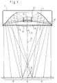
- a hollow ring reflector 14 with a central axis 23 is arranged in the downwardly open housing 11 of an operating light according to the invention, which is essentially parabolic or partially spherical and has a light exit opening 12 at the bottom, which is open through an opening Side of the housing provided translucent pane 18 is covered, for example, from cathedral glass.
- the disk 18 has an opening 19 in the center in which a plate arrangement 20 is fastened with a handle 21 for pivoting the housing 11.
- a lamp 13 is fastened above the plate arrangement 20 in the region of the focal point of the hollow reflector 14 and is surrounded by a circular cylindrical filter 22 which absorbs primarily IR radiation and which detects all of the light radiation reaching the hollow reflector 14 and can also filter out UV components.
- the hollow reflector 14 is parabolic or part-spherical in most of its surface in order to concentrate the light emitted by the lamp 13 on an operating field 24 in a main light field 15 arranged at a distance below the housing 11 and around the central axis 23 of the housing 11
- the lower region of the hollow reflector 14 is slightly convexly curved and finally widened conically outwards in such a way that an annular region 14 'concentric with the central axis 23 is formed in the lower end region of the hollow reflector 14, which is there incident light from the lamp 13 specifically directed into a light environment 17 which surrounds the main light field 15 radially adjacent.
- the design and size of the annular area 14 ' are selected such that the light environment 17 is also uniformly illuminated, but with a significantly reduced illuminance in the ratio of e.g. 1:30 in relation to the illuminance in the main light field 15.
- FIG. 3 shows the light distribution that can be achieved by the surgical light described, the dependence the illuminance in kilo-lux from the radius of the main light field 15 or the concentric light environment 17 is shown schematically.
- This diagram shows that the maximum illuminance in the area of the central axis 23 of the housing 11 is over 100 klx and then drops to a value well below 10 klx up to an area with a radius of approximately 28 cm, which is the illuminance in the light environment 17 corresponds. From this radius onwards, the illuminance remains approximately constant up to a diameter of approx. 50 cm or only drops slightly here, in order to finally change to the illuminance R of the room lighting, which is approx. 1 klx, at a diameter of approx. 60 cm.
- the illuminance b in the light environment 17 is approximately 5 to 30 klx.
- the ring hollow reflector 14 is parabolic or partially spherical up to its largest diameter.
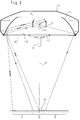
- an auxiliary ring reflector 16 is arranged within the upper central opening of the hollow reflector 14, which has an inclination and / or curvature such that the light of the lamp 13 striking it via a part of the main hollow reflector 14 into the light environment 17 and the main light field 15 is directed so that the overlap in the main light field 15, even when the working distance between the main light field 15 and the light environment 17 changes, can never result in an illumination gap.
Landscapes
- Engineering & Computer Science (AREA)
- General Engineering & Computer Science (AREA)
- Non-Portable Lighting Devices Or Systems Thereof (AREA)
Abstract
Description
Die Erfindung betrifft eine Operationsleuchte nach dem Oberbegriff des Patentanspruchs 1.The invention relates to an operating light according to the preamble of
Derartige Leuchten sind z.B. aus den deutschen Patentschriften 32 43 709 und 32 43 710 bekannt. Durch geeignete Ausbildung des Hohlreflektors wird erreicht, daß der Bereich einer medizinischen Operation möglichst hell und schattenfrei ausgeleuchtet wird. Um das Licht der mittig positionierten Lampe optimal auszunutzen, hat man bereits unterhalb der Lampe einen ringförmigen Zusatzreflektor befestigt, der in den Hohlreflektor hineinbeweglich ist, um einen Teil des Lampenlichtes steiler auf das Operationsfeld auftreffen zu lassen (EP 0 468 287 B1). Weiter hat man zwecks Verkleinerung des Hohlreflektors bei gleichbleibender Beleuchtungsstärke schon Hilfs-Ringreflektoren innerhalb des Haupt-Hohlreflektors vorgesehen (DE-OS 41 40 325).Such lights are e.g. known from German patents 32 43 709 and 32 43 710. A suitable design of the hollow reflector ensures that the area of a medical operation is illuminated as brightly as possible and free of shadows. In order to make optimal use of the light from the centrally positioned lamp, a ring-shaped additional reflector has been attached below the lamp, which can be moved into the hollow reflector in order to allow part of the lamp light to strike the operating field more steeply (EP 0 468 287 B1). Furthermore, auxiliary ring reflectors have already been provided within the main hollow reflector for the purpose of reducing the size of the hollow reflector while maintaining the illuminance (DE-OS 41 40 325).
Zweck der besonderen Maßnahmen an bekannten Ring-Hohlreflektoren ist es jeweils, ein möglichst gleichmäßig ausgeleuchtetes, begrenztes Lichtfeld mit einem Durchmesser von ca. 15 bis 30 cm zu erhalten. Hierbei sind in jüngster Zeit immer hellere Lampen und besser reflektierende Hohlreflektoren verwendet worden, da blutendes Fleisch in einer offenen Wunde einen hohen Teil des auftreffenden Lichtes absorbiert und nur einen geringen Teil reflektiert, so daß der Operateur nur bei ausreichend hoher Beleuchtungsstärke den Operationsvorgang einwandfrei beobachten kann. Heutzutage werden bei Operationsleuchten Beleuchtungsstärken bis zu 150 000 Lux erreicht, was jedoch auf einem hellen Untergrund ein unerträglich helles und gleißendes Licht ergibt, welches die Augen rasch ermüdet. Da das in einem Operationssaal zur Verfügung stehende Raumlicht eine Beleuchtungsstärke von etwa 1000 Lux erzeugen soll, beträgt das Verhältnis der maximalen Beleuchtungsstärke der Operationsleuchte zu derjenigen der Raumbeleuchtung 150:1. Dies führt zu einer starken Ermüdung der Augen.The purpose of the special measures on known hollow ring reflectors is in each case to obtain a light field which is illuminated as uniformly as possible and has a diameter of approximately 15 to 30 cm. In recent times, ever brighter lamps and better reflecting hollow reflectors have been used, since bleeding meat in an open wound absorbs a large part of the incident light and reflects only a small part, so that the surgeon can only properly observe the operation when the illuminance is sufficiently high . Nowadays, illuminance levels of up to 150,000 lux are achieved with surgical lights, but this results in an unbearably bright and glaring light on a light background, which quickly tires the eyes. Since the room light available in an operating room has an illuminance of approximately Should generate 1000 lux, the ratio of the maximum illuminance of the surgical light to that of the room lighting is 150: 1. This leads to severe eye fatigue.
Das Ziel der vorliegenden Erfindung besteht darin, eine Operationsleuchte der eingangs genannten Gattung zu schaffen, welche mit höchsten Beleuchtungsstärken arbeiten kann, ohne daß die Augen des Operateurs ermüden.The aim of the present invention is to provide an operating light of the type mentioned at the outset, which can work with the highest illuminance levels without tiring the operator's eyes.
Zur Lösung dieser Aufgabe sind die Merkmale des kennzeichnenden Teils des Patentanspruchs 1 vorgesehen. Bevorzugte Ausführungsformen entnimmt man den Ansprüchen 2 bis 6.To achieve this object, the features of the characterizing part of
Der Erfindungsgedanke ist also darin zu sehen, daß über das aufgrund von nicht zu vermeidenden Streueffekten und Unvollkommenheiten der Reflektoren auftretende schwache Lichtumfeld um das Hauptlichtfeld herum hinausgezielt und bewußt ein unmittelbar an das Hauptlichtfeld rundum angrenzendes Lichtumfeld erzeugt wird, welches hinsichtlich seiner Beleuchtungsstärke in einem solchen Verhältnis zur Beleuchtungsstärke des Hauptlichtfeldes steht, daß einer Ermüdung der Augen des Operateurs zumindest in erheblichem Maße entgegengewirkt wird. Auf diese Weise ist es möglich, eine Abstufung zwischen der maximalen Beleuchtungsstärke im Hauptlichtfeld und im Lichtumfeld von etwa nur noch 30:1 zu erzielen. Beachtet man den Umstand, daß idealerweise die sehr helle Operationsfeld-Beleuchtung nur in die stark absorbierende Wunde fällt und die erfindungsgemäße Umfeldbeleuchtung auf die nicht so stark absorbierende Umgebung, z.B. grüne Operationstücher, so ist der Unterschied des vom Auge tatsächlich erfaßten, reflektierten Lichts der Wunde und des Umfeldes aufgrund der erfindungsgemäßen Maßnahmen sehr gering. Hierdurch wird eine frühzeitige Ermüdung der Augen verhindert. Hätte man demgegenüber ein System mit ähnlich hohem Spitzenwert der Beleuchtungsstärke und einer nicht stufenartig, sondern gleichmäßig abfallenden Beleuchtungsstärke im Umfeld, so würde sich durch die starke Absorption der Wunde und die geringe Absorption des Umfeldes der Effekt eines dunklen Loches in der Mitte ergeben. Dies ist unerwünscht. Erfindungsgemäß kommt es also darauf an, daß der Abfall von der Lichtstärke im Hauptlichtfeld zum Lichtumfeld über eine möglichst kurze Strecke erfolgt, die bei wenigen cm liegen sollte.The idea of the invention is therefore to be seen in the fact that beyond the weak light environment that occurs due to the unavoidable scattering effects and imperfections of the reflectors, the aim is to create a consciously generated light environment that is directly adjacent to the main light field and that is in such a ratio with regard to its illuminance The illuminance of the main light field means that fatigue in the eyes of the surgeon is counteracted, at least to a considerable extent. In this way it is possible to achieve a gradation between the maximum illuminance in the main light field and in the light environment of only about 30: 1. If one takes into account the fact that ideally the very bright operating field lighting only falls into the highly absorbing wound and the surrounding lighting according to the invention onto the less absorbing environment, for example green surgical drapes, the difference is the reflected light of the wound that is actually detected by the eye and the environment due to the measures according to the invention very low. This prevents premature eye fatigue. If you had a system with a similarly high peak illuminance and a not gradually decreasing illuminance in the surroundings, so the strong absorption of the wound and the low absorption of the surroundings would result in the effect of a dark hole in the middle. This is undesirable. According to the invention, it is important that the drop from the light intensity in the main light field to the light environment takes place over the shortest possible distance, which should be a few cm.
Innerhalb des Hauptlichtfeldes und insbesondere des Lichtumfeldes sollte die Beleuchtungsstärke möglichst konstant sein und radial nach außen möglichst wenig abfallen. Der Außendurchmesser des erfindungsgemäßen Lichtumfeldes liegt bei etwa 50 bis 90 cm, sollte jedoch zumindest 40 cm betragen.Within the main light field and in particular the light environment, the illuminance should be as constant as possible and decrease as little as possible radially outwards. The outside diameter of the light environment according to the invention is about 50 to 90 cm, but should be at least 40 cm.
Die Erfindung wird im folgenden beispielsweise anhand der Zeichnung beschrieben; in dieser zeigt:
Figur 1- eine schematische Seitenansicht einer erfindungsgemäßen Operationsleuchte mit dem darunter befindlichen Operationsfeld nach einer ersten Ausführungsform der Erfindung,
- Figur 2
- eine entsprechende schematische Ansicht einer anderen Ausführungsform und
- Figur 3
- ein Diagramm der Abhängigkeit der Beleuchtungsstärke B in Kilolux in Abhängigkeit vom Radius r des
kreisförmigen Operationsfeldes 24.
- Figure 1
- 1 shows a schematic side view of an operating light according to the invention with the operating field underneath according to a first embodiment of the invention,
- Figure 2
- a corresponding schematic view of another embodiment and
- Figure 3
- a diagram of the dependence of the illuminance B in kilolux as a function of the radius r of the
circular operating field 24.
Nach Figur 1 ist im nach unten offenen Gehäuse 11 einer erfindungsgemäßen Operationsleuchte ein Ring-Hohlreflektor 14 mit einer Mittelachse 23 angeordnet, der im wesentlichen parabol- oder teilsphärisch ausgebildet ist und unten eine Lichtaustrittsöffnung 12 aufweist, die durch eine an der offenen Seite des Gehäuses vorgesehene lichtdurchlässige Scheibe 18 z.B. aus Kathedralglas abgedeckt ist. Die Scheibe 18 weist zentral eine Öffnung 19 auf, in der eine Plattenanordnung 20 mit einem Handgriff 21 zur Verschwenkung des Gehäuses 11 befestigt ist.According to FIG. 1, a
Oberhalb der Plattenanordnung 20 ist im Bereich des Brennpunktes des Hohlreflektors 14 eine Lampe 13 befestigt, die von einem in erster Linie IR-Strahlung absorbierenden kreiszylindrischen Filter 22 umgeben ist, welches die gesamte zum Hohlreflektor 14 gelangende Lichtstrahlung erfaßt und auch UV-Anteile ausfiltern kann.A
Während der Hohlreflektor 14 im größten Teil seiner Oberfläche parabol- oder teilsphärisch ausgebildet ist, um das von der Lampe 13 abgestrahlte Licht auf einem Operationsfeld 24 in einem im Abstand unterhalb des Gehäuses 11 angeordneten Hauptlichtfeld 15 zu konzentrieren und das um die Mittelachse 23 des Gehäuses 11 rotationssymmetrische Hauptlichtfeld 15 weitgehend gleichmäßig auszuleuchten, ist der untere Bereich des Hohlreflektors 14 in der Weise leicht konvex gekrümmt und schließlich sich konisch nach außen erweiternd ausgebildet, daß im unteren Endbereich des Hohlreflektors 14 ein zur Mittelachse 23 konzentrischer ringförmiger Bereich 14' entsteht, der das dort auftreffende Licht von der Lampe 13 gezielt in ein Lichtumfeld 17 lenkt, welches das Hauptlichtfeld 15 radial angrenzend umgibt. Die Ausbildung und Größe des ringförmigen Bereiches 14' sind derart gewählt, daß auch das Lichtumfeld 17 gleichmäßig ausgeleuchtet wird, jedoch mit einer deutlich herabgesetzten Beleuchtungsstärke im Verhältnis von z.B. 1:30 im Verhältnis zur Beleuchtungsstärke im Hauptlichtfeld 15.While the
In Figur 3 ist die durch die beschriebene Operationsleuchte erzielbare Lichtverteilung gezeigt, wobei die Abhängigkeit der Beleuchtungsstärke in Kilo-Lux vom Radius des Hauptlichtfeldes 15 bzw. des dazu konzentrischen Lichtumfeldes 17 schematisch wiedergegeben ist.FIG. 3 shows the light distribution that can be achieved by the surgical light described, the dependence the illuminance in kilo-lux from the radius of the
Man erkennt an diesem Diagramm, daß die maximale Beleuchtungsstärke im Bereich der Mittelachse 23 des Gehäuses 11 über 100 klx beträgt und dann bis zu einem Bereich bei einem Radius von etwa 28 cm auf einen Wert deutlich unter 10 klx abfällt, was der Beleuchtungsstärke im Lichtumfeld 17 entspricht. Von diesem Radius ab bleibt die Beleuchtungsstärke bis zu einem Durchmesser von etwa 50 cm annähernd konstant bzw. fällt hier nur leicht ab, um dann schließlich bei einem Durchmesser von etwa 60 cm in die Beleuchtungsstärke R der Raumbeleuchtung überzugehen, welche bei etwa 1 klx liegt. Die Beleuchtungsstärke b im Lichtumfeld 17 liegt bei etwa 5 bis 30 klx.This diagram shows that the maximum illuminance in the area of the
Bei der Ausführungsform nach Figur 2 bezeichnen gleiche Bezugszahlen entsprechende Bauteile wie in Figur 1.In the embodiment according to FIG. 2, the same reference numerals designate corresponding components as in FIG. 1.
Im Gegensatz zur Ausführungsform nach Figur 1 verläuft der Ring-Hohlreflektor 14 bis zu seinem größten Durchmesser parabolisch bzw. teilsphärisch. Innerhalb der oberen Mittelöffnung des Hohlreflektors 14 ist jedoch ein Hilfs-Ringreflektor 16 angeordnet, welcher eine derartige Neigung und/oder Krümmung aufweist, daß das auf ihn auftreffende Licht der Lampe 13 über einen Teil des Haupt-Hohlreflektors 14 in das Lichtumfeld 17 und das Hauptlichtfeld 15 gelenkt wird, so daß durch die Überlappung im Hauptlichtfeld 15 auch bei Änderung des Arbeitsabstandes zwischen Hauptlichtfeld 15 und Lichtumfeld 17 nie eine Beleuchtungslücke entstehen kann.In contrast to the embodiment according to FIG. 1, the ring
- 1111
- Gehäusecasing
- 1212th
- LichtaustrittsöffnungLight exit opening
- 1313
- Lampelamp
- 1414
- Ring-HohlreflektorRing hollow reflector
- 1515
- HauptlichtfeldMain light field
- 1616
- Hilfs-RingreflektorAuxiliary ring reflector
- 1717th
- LichtumfeldLighting environment
- 1818th
- Scheibedisc
- 1919th
- Öffnungopening
- 2020th
- PlattenanordnungPlate arrangement
- 2121
- HandgriffHandle
- 2222
- Filterfilter
- 2323
- MittelachseCentral axis
- 2424th
- OperationsfeldOperating field
- bb
-
Beleuchtungsstärke des Lichtumfeldes 17Illuminance of the
light environment 17 - dd
-
Außendurchmesser des Lichtumfeldes 17Outside diameter of the
light environment 17 - rr
- Radiusradius
- RR
- RaumbeleuchtungsstärkeRoom illuminance
Claims (6)
dadurch gekennzeichnet,
daß der Hohlreflektor (14) und/oder wenigstens ein in seinem Bereich angeordneter und insbesondere zu ihm konzentrischer Hilfs-Hohlreflektor (16) so ausgebildet und/oder angeordnet ist bzw. sind, daß ein Teil der von der Lichtquelle (13) abgegebenen Lichtstrahlen in ein sich um das Hauptlichtfeld (15) erstreckendes, vorzugsweise an dieses angrenzendes Lichtumfeld (17) gelenkt ist, derart, daß ein hell ausgeleuchtetes Hauptlichtfeld (15) und ein abgestuft weniger hell ausgeleuchtetes Lichtumfeld (17) vorliegt.Operating light with a housing (11) at the bottom with a light exit opening (12), in which a light source (13) is arranged centrally, which directs light all around to a preferably annular hollow reflector (14) which is arranged in the housing (11) and which reflects the incident light rays deflected towards the light exit opening (12) and concentrated as uniformly as possible on a main light field (15) arranged at a distance from the light exit opening (12),
characterized by
that the hollow reflector (14) and / or at least one auxiliary hollow reflector (16) arranged in its area and in particular concentric to it is designed and / or arranged such that part of the light rays emitted by the light source (13) in a light environment (17) extending around the main light field (15), preferably adjacent to it, is directed such that a brightly illuminated main light field (15) and a graded less brightly illuminated light environment (17) are present.
dadurch gekennzeichnet,
daß das Verhältnis der Beleuchtungsstärken des Hauptlichtfeldes (15) und des Lichtumfeldes (17) sich wie 50:1 bis 5:1, vorzugsweise 40:1 bis 20:1 und insbesondere etwa 30:1 beträgt.Operating light according to claim 1,
characterized by
that the ratio of the illuminance of the main light field (15) and the light environment (17) is like 50: 1 to 5: 1, preferably 40: 1 to 20: 1 and in particular about 30: 1.
dadurch gekennzeichnet,
daß sich die Außendurchmesser des Hauptlichtfeldes (15) und des Lichtumfeldes (17) wie 1:2 bis 1:10 und insbesondere etwa 1:3 verhalten.Operating light according to claim 1 or 2,
characterized by
that the outer diameter of the main light field (15) and the light environment (17) behave like 1: 2 to 1:10 and in particular about 1: 3.
dadurch gekennzeichnet,
daß der Hohlreflektor (14) einen oder mehrere kreisringförmige Bereiche (14') aufweist, welche so gerichtet und/oder gekrümmt sind, daß sie das Lichtumfeld (17) möglichst gleichmäßig ausleuchten, während der Rest des Hohlreflektors (14) das Hauptlicht (15) beaufschlagt und möglichst gleichmäßig ausleuchtet.Operating light according to one of the preceding claims,
characterized by
that the hollow reflector (14) has one or more annular regions (14 ') which are directed and / or curved in such a way that they illuminate the light environment (17) as uniformly as possible, while the rest of the hollow reflector (14) the main light (15) acted upon and illuminated as evenly as possible.
dadurch gekennzeichnet,
daß im oder am Hohlreflektor (14) ein kreisringförmiger Hilfs-Hohlreflektor (16) angeordnet ist, welcher so ausgebildet und/oder angeordnet ist, daß er das Lichtumfeld (17) und das Hauptlichtfeld (15) über einen Bereich des Hohlreflektors (14) beaufschlagt, während der Hohlreflektor (14) zumindest im wesentlichen nur für die Erzeugung des Hauptlichtfeldes (15) allein verantwortlich ist.Operating light according to one of the preceding claims,
characterized by
that in or on the hollow reflector (14) an annular auxiliary hollow reflector (16) is arranged, which is designed and / or arranged such that it acts on the light environment (17) and the main light field (15) over a region of the hollow reflector (14) , while the hollow reflector (14) is at least essentially only responsible for the generation of the main light field (15).
dadurch gekennzeichnet,
daß bestimmte Bereiche des Hohlreflektors (14) und/oder des Hilfs-Hohlreflektors (16) mit einer derartig behandelten, z.B. mattierten oder strukturierten Oberfläche ausgestattet sind, daß hierdurch ein weich ausgeleuchtetes Lichtumfeld (17) erzeugt wird.Operating light according to one of the preceding claims,
characterized by
that certain areas of the hollow reflector (14) and / or the auxiliary hollow reflector (16) are equipped with a surface treated in this way, for example with a matt or structured surface, so that a softly illuminated light environment (17) is generated as a result.
Applications Claiming Priority (2)
| Application Number | Priority Date | Filing Date | Title |
|---|---|---|---|
| DE19644959 | 1996-10-29 | ||
| DE19644959A DE19644959A1 (en) | 1996-10-29 | 1996-10-29 | Operating light |
Publications (2)
| Publication Number | Publication Date |
|---|---|
| EP0840059A2 true EP0840059A2 (en) | 1998-05-06 |
| EP0840059A3 EP0840059A3 (en) | 1999-09-08 |
Family
ID=7810327
Family Applications (1)
| Application Number | Title | Priority Date | Filing Date |
|---|---|---|---|
| EP97116551A Withdrawn EP0840059A3 (en) | 1996-10-29 | 1997-09-23 | Operating lamp |
Country Status (3)
| Country | Link |
|---|---|
| US (1) | US6132067A (en) |
| EP (1) | EP0840059A3 (en) |
| DE (1) | DE19644959A1 (en) |
Cited By (1)
| Publication number | Priority date | Publication date | Assignee | Title |
|---|---|---|---|---|
| CN103807625A (en) * | 2012-11-12 | 2014-05-21 | 南昌迈柯尔医疗器械有限公司 | Integral reflection LED (light emitting diode) lamp holder device and shadowless lamp using device |
Families Citing this family (5)
| Publication number | Priority date | Publication date | Assignee | Title |
|---|---|---|---|---|
| TW563264B (en) * | 2002-10-11 | 2003-11-21 | Highlink Technology Corp | Base of optoelectronic device |
| US6874914B2 (en) * | 2002-12-04 | 2005-04-05 | Sage Technology, Llc | Adjustable lighting system |
| US8016470B2 (en) * | 2007-10-05 | 2011-09-13 | Dental Equipment, Llc | LED-based dental exam lamp with variable chromaticity |
| CN101451678A (en) * | 2007-12-06 | 2009-06-10 | 富士迈半导体精密工业(上海)有限公司 | Solid lighting device |
| EP3812649A4 (en) * | 2018-06-22 | 2021-06-02 | Nanjing Mindray Bio-Medical Electronics Co., Ltd. | SURGICAL LAMP |
Citations (4)
| Publication number | Priority date | Publication date | Assignee | Title |
|---|---|---|---|---|
| DE3243709C2 (en) | 1982-11-25 | 1990-10-31 | Delma, Elektro- Und Medizinische Apparatebaugesellschaft Mbh, 7200 Tuttlingen, De | |
| DE3243710C2 (en) | 1982-11-25 | 1991-12-12 | Delma, Elektro- Und Medizinische Apparatebaugesellschaft Mbh, 7200 Tuttlingen, De | |
| DE4140325A1 (en) | 1991-12-06 | 1993-06-09 | Delma Elektro- Und Medizinische Apparatebau Gmbh, 7200 Tuttlingen, De | Lighting assembly for operating theatre - has central light source and auxiliary reflector in addition to main reflector for capturing light which escapes main reflector. |
| EP0468287B1 (en) | 1990-07-23 | 1994-05-18 | DELMA ELEKTRO-UND MEDIZINISCHE APPARATEBAU GESELLSCHAFT mbH | Operating lamp |
Family Cites Families (19)
| Publication number | Priority date | Publication date | Assignee | Title |
|---|---|---|---|---|
| US1286535A (en) * | 1917-12-19 | 1918-12-03 | Wesley E Cochran | Lighting-fixture. |
| DE483950C (en) * | 1926-02-16 | 1929-10-08 | Koerting & Mathiesen A G | Coal arc lamp for therapeutic purposes |
| US2126650A (en) * | 1935-09-09 | 1938-08-09 | Superlux Corp | Lighting device |
| DE849832C (en) * | 1950-08-26 | 1952-09-18 | Hueper & Schmidt K G | Shadow-free reflector, especially for surgical purposes |
| FR1045467A (en) * | 1951-11-26 | 1953-11-26 | Lighting device, in particular for the operating field | |
| FR66975E (en) * | 1954-10-02 | 1957-11-04 | Lighting device, in particular for the operating field | |
| US4280167A (en) * | 1979-09-13 | 1981-07-21 | Ellett Edwin W | Operating room surgical lamp |
| US4447865A (en) * | 1982-05-13 | 1984-05-08 | General Electric Company | Reflector lamp |
| DE3238876C2 (en) * | 1982-10-18 | 1985-01-17 | Franz Sill Gmbh, 1000 Berlin | Reflector for a recessed ceiling light fitted with a high pressure discharge lamp |
| US4651257A (en) * | 1985-07-15 | 1987-03-17 | American Sterilizer Company | Multiple source lighting fixture |
| US4617619A (en) * | 1985-10-02 | 1986-10-14 | American Sterilizer Company | Reflector for multiple source lighting fixture |
| DE3605226A1 (en) * | 1986-02-19 | 1987-08-27 | Daume & Jordan Gmbh & Co Kg | GLARE-FREE LAMP WITH STRIP-SHADE DIMMING REFLECTOR |
| DE3638669A1 (en) * | 1986-11-12 | 1988-05-26 | Auer Sog Glaswerke Gmbh | REFLECTOR FOR DENTAL AND SURGICAL OPERATING LIGHTS |
| US5001616A (en) * | 1990-03-16 | 1991-03-19 | American Sterilizer Company | Optical system for lighting fixture |
| US5067064A (en) * | 1990-03-16 | 1991-11-19 | American Sterilizer Company | Pattern change mechanism |
| DE4033625A1 (en) * | 1990-10-23 | 1992-04-30 | Bieroth Heinz | Operating table lighting with adjustable head and light guide - enables head to be positioned away from hot light source, reducing interference with extn. of air |
| US5373430A (en) * | 1992-04-16 | 1994-12-13 | Mcdermott; Kevin | Wide angle beam pattern lamp |
| US5582478A (en) * | 1993-10-29 | 1996-12-10 | Ambrosino; Donald J. | Food covering system with illuminating and/or moving decorations |
| US5791768A (en) * | 1997-04-17 | 1998-08-11 | Stingray Lighting, Inc. | Dual reflector lighting system |
-
1996
- 1996-10-29 DE DE19644959A patent/DE19644959A1/en not_active Withdrawn
-
1997
- 1997-09-23 EP EP97116551A patent/EP0840059A3/en not_active Withdrawn
- 1997-10-28 US US08/958,807 patent/US6132067A/en not_active Expired - Fee Related
Patent Citations (4)
| Publication number | Priority date | Publication date | Assignee | Title |
|---|---|---|---|---|
| DE3243709C2 (en) | 1982-11-25 | 1990-10-31 | Delma, Elektro- Und Medizinische Apparatebaugesellschaft Mbh, 7200 Tuttlingen, De | |
| DE3243710C2 (en) | 1982-11-25 | 1991-12-12 | Delma, Elektro- Und Medizinische Apparatebaugesellschaft Mbh, 7200 Tuttlingen, De | |
| EP0468287B1 (en) | 1990-07-23 | 1994-05-18 | DELMA ELEKTRO-UND MEDIZINISCHE APPARATEBAU GESELLSCHAFT mbH | Operating lamp |
| DE4140325A1 (en) | 1991-12-06 | 1993-06-09 | Delma Elektro- Und Medizinische Apparatebau Gmbh, 7200 Tuttlingen, De | Lighting assembly for operating theatre - has central light source and auxiliary reflector in addition to main reflector for capturing light which escapes main reflector. |
Cited By (1)
| Publication number | Priority date | Publication date | Assignee | Title |
|---|---|---|---|---|
| CN103807625A (en) * | 2012-11-12 | 2014-05-21 | 南昌迈柯尔医疗器械有限公司 | Integral reflection LED (light emitting diode) lamp holder device and shadowless lamp using device |
Also Published As
| Publication number | Publication date |
|---|---|
| US6132067A (en) | 2000-10-17 |
| DE19644959A1 (en) | 1998-04-30 |
| EP0840059A3 (en) | 1999-09-08 |
Similar Documents
| Publication | Publication Date | Title |
|---|---|---|
| EP0468287B1 (en) | Operating lamp | |
| CH671455A5 (en) | ||
| EP0982534A2 (en) | Lamp for forming a shadowless light field | |
| EP0191264B2 (en) | Non-blinding device for large-area lighting fixtures | |
| DE4140325C2 (en) | surgical light | |
| EP0840059A2 (en) | Operating lamp | |
| DE1259747B (en) | Arrangement for preventing phantom light in a signal light system for Automobileod. like | |
| DE19758551B4 (en) | Bicycle tail light with at least two LEDs | |
| DE561639C (en) | Electric double filament lamp for headlights on motor vehicles | |
| DE4312889B4 (en) | Mainly direct luminaire with a suspended light guide | |
| EP1045195B1 (en) | Luminaire | |
| DE10139002A1 (en) | Built-in floor light has light source beneath light outlet slit, reflector reflecting light from source upwards to second reflector that reflects light to emanate from slit essentially horizontally | |
| DE3827834A1 (en) | Fresnel lens | |
| DE2901320A1 (en) | Spotlight with point-shaped source, reflector and condenser lens - has additional rotationally symmetric dispersion lens diffusing beam in section of room | |
| EP1072840B1 (en) | Luminaire | |
| DE102023103126B4 (en) | Light-diffusing attachment for a lamp and lamp | |
| DE1183873B (en) | Headlights for color signals, especially for traffic control | |
| EP1848919B1 (en) | Recessed light | |
| DE3807584A1 (en) | Surgical luminaire | |
| DE2217421A1 (en) | DEVICE FOR CONFLICTING RAYS | |
| EP0994294A2 (en) | Lighting apparatus to be mounted to a first wall defining a light emitting window | |
| DE202023101390U1 (en) | Light diffusing attachment for a lamp and lamp | |
| DE2219416A1 (en) | BOLLARD LIGHT | |
| DE2731671A1 (en) | Ceiling lamp with reflector and light refracting element - is fitted with ring shaped transparent element to refract light rays at predetermined angle | |
| DE861087C (en) | Reflector system for lighting devices |
Legal Events
| Date | Code | Title | Description |
|---|---|---|---|
| PUAI | Public reference made under article 153(3) epc to a published international application that has entered the european phase |
Free format text: ORIGINAL CODE: 0009012 |
|
| AK | Designated contracting states |
Kind code of ref document: A2 Designated state(s): AT BE CH DE DK ES FI FR GB GR IE IT LI LU MC NL PT SE |
|
| AX | Request for extension of the european patent |
Free format text: AL;LT;LV;RO;SI |
|
| ITCL | It: translation for ep claims filed |
Representative=s name: DALLA ROSA ADRIANO |
|
| PUAL | Search report despatched |
Free format text: ORIGINAL CODE: 0009013 |
|
| AK | Designated contracting states |
Kind code of ref document: A3 Designated state(s): AT BE CH DE DK ES FI FR GB GR IE IT LI LU MC NL PT SE |
|
| AX | Request for extension of the european patent |
Free format text: AL;LT;LV;RO;SI |
|
| AKX | Designation fees paid | ||
| REG | Reference to a national code |
Ref country code: DE Ref legal event code: 8566 |
|
| STAA | Information on the status of an ep patent application or granted ep patent |
Free format text: STATUS: THE APPLICATION IS DEEMED TO BE WITHDRAWN |
|
| 18D | Application deemed to be withdrawn |
Effective date: 20000309 |