EP0839294B1 - Schrittgetriebe - Google Patents
Schrittgetriebe Download PDFInfo
- Publication number
- EP0839294B1 EP0839294B1 EP97923013A EP97923013A EP0839294B1 EP 0839294 B1 EP0839294 B1 EP 0839294B1 EP 97923013 A EP97923013 A EP 97923013A EP 97923013 A EP97923013 A EP 97923013A EP 0839294 B1 EP0839294 B1 EP 0839294B1
- Authority
- EP
- European Patent Office
- Prior art keywords
- cam plates
- cam
- rotation
- roller
- supporting member
- Prior art date
- Legal status (The legal status is an assumption and is not a legal conclusion. Google has not performed a legal analysis and makes no representation as to the accuracy of the status listed.)
- Expired - Lifetime
Links
Images




Classifications
-
- F—MECHANICAL ENGINEERING; LIGHTING; HEATING; WEAPONS; BLASTING
- F16—ENGINEERING ELEMENTS AND UNITS; GENERAL MEASURES FOR PRODUCING AND MAINTAINING EFFECTIVE FUNCTIONING OF MACHINES OR INSTALLATIONS; THERMAL INSULATION IN GENERAL
- F16H—GEARING
- F16H27/00—Step-by-step mechanisms without freewheel members, e.g. Geneva drives
- F16H27/04—Step-by-step mechanisms without freewheel members, e.g. Geneva drives for converting continuous rotation into a step-by-step rotary movement
-
- B—PERFORMING OPERATIONS; TRANSPORTING
- B23—MACHINE TOOLS; METAL-WORKING NOT OTHERWISE PROVIDED FOR
- B23Q—DETAILS, COMPONENTS, OR ACCESSORIES FOR MACHINE TOOLS, e.g. ARRANGEMENTS FOR COPYING OR CONTROLLING; MACHINE TOOLS IN GENERAL CHARACTERISED BY THE CONSTRUCTION OF PARTICULAR DETAILS OR COMPONENTS; COMBINATIONS OR ASSOCIATIONS OF METAL-WORKING MACHINES, NOT DIRECTED TO A PARTICULAR RESULT
- B23Q16/00—Equipment for precise positioning of tool or work into particular locations not otherwise provided for
- B23Q16/02—Indexing equipment
- B23Q16/022—Indexing equipment in which only the indexing movement is of importance
- B23Q16/025—Indexing equipment in which only the indexing movement is of importance by converting a continuous movement into a rotary indexing movement
-
- B—PERFORMING OPERATIONS; TRANSPORTING
- B23—MACHINE TOOLS; METAL-WORKING NOT OTHERWISE PROVIDED FOR
- B23Q—DETAILS, COMPONENTS, OR ACCESSORIES FOR MACHINE TOOLS, e.g. ARRANGEMENTS FOR COPYING OR CONTROLLING; MACHINE TOOLS IN GENERAL CHARACTERISED BY THE CONSTRUCTION OF PARTICULAR DETAILS OR COMPONENTS; COMBINATIONS OR ASSOCIATIONS OF METAL-WORKING MACHINES, NOT DIRECTED TO A PARTICULAR RESULT
- B23Q5/00—Driving or feeding mechanisms; Control arrangements therefor
- B23Q5/22—Feeding members carrying tools or work
- B23Q5/34—Feeding other members supporting tools or work, e.g. saddles, tool-slides, through mechanical transmission
- B23Q5/50—Feeding other members supporting tools or work, e.g. saddles, tool-slides, through mechanical transmission feeding step-by-step
-
- Y—GENERAL TAGGING OF NEW TECHNOLOGICAL DEVELOPMENTS; GENERAL TAGGING OF CROSS-SECTIONAL TECHNOLOGIES SPANNING OVER SEVERAL SECTIONS OF THE IPC; TECHNICAL SUBJECTS COVERED BY FORMER USPC CROSS-REFERENCE ART COLLECTIONS [XRACs] AND DIGESTS
- Y10—TECHNICAL SUBJECTS COVERED BY FORMER USPC
- Y10T—TECHNICAL SUBJECTS COVERED BY FORMER US CLASSIFICATION
- Y10T74/00—Machine element or mechanism
- Y10T74/14—Rotary member or shaft indexing, e.g., tool or work turret
- Y10T74/1418—Preselected indexed position
- Y10T74/1424—Sequential
- Y10T74/1441—Geneva or mutilated gear drive
-
- Y—GENERAL TAGGING OF NEW TECHNOLOGICAL DEVELOPMENTS; GENERAL TAGGING OF CROSS-SECTIONAL TECHNOLOGIES SPANNING OVER SEVERAL SECTIONS OF THE IPC; TECHNICAL SUBJECTS COVERED BY FORMER USPC CROSS-REFERENCE ART COLLECTIONS [XRACs] AND DIGESTS
- Y10—TECHNICAL SUBJECTS COVERED BY FORMER USPC
- Y10T—TECHNICAL SUBJECTS COVERED BY FORMER US CLASSIFICATION
- Y10T74/00—Machine element or mechanism
- Y10T74/18—Mechanical movements
- Y10T74/18528—Rotary to intermittent unidirectional motion
Definitions
- the invention relates to a step transmission according to the preamble of claim 1.
- a roller carrier with two identical, but acts with respect to each other, cam disks arranged in mirror image together.
- Each of these has one concentric to its axis of rotation Stopping area that is continuously about 250 ° extends, as well as one formed on a projection Range of motion and a trough, each about 55 ° extend.
- the first of these two Kuveninn follows on the holding area only the projection with the range of motion and then the hollow; it is with the second cam vice versa.
- the protrusion of the first cam disc takes 360 ° each having a first role of the role bearer while on it the following second role is not touched by any cam, the third roller is immersed in the trough of the second cam and the fourth role also from no cam is touched.
- the third roll ends the trough of the has reached the second cam, it is from the projection taken away while the first roll from the first cam is released and the trough takes on the second role.
- the third role is from the second cam released and the second and fourth roles one of the cams is in contact with the holding area, so that the roller carrier was prevented from turning further after a quarter turn is until the two cams turn one full turn have executed.
- the number is Switch positions, which is connected to the roller carrier Revolvers or the like can take up with the number of Identical roles on the roller carrier. With only four switch positions this has the consequence that predetermined on a roller carrier Outside diameter only relatively small rolls can be accommodated; this is especially true when six or more switch positions are required and therefore one a correspondingly large number of roles is required. Because of her thus, the dimensioning can not be special with the roles high forces as required are to the roller carrier against the impact of a large to securely hold the external torque. External torques in significant size occur, for example, when the stepper gear provided for driving a turret of a lathe is that in each of its switch positions only by the Stepper gear prevented from rotating, so not by an additional Device is locked.
- the invention has for its object a stepping gear, which is particularly useful for switching turrets on lathes or the like. Is suitable to develop such that it is given Size of the cam discs and the roller carrier suitable is particularly high acting on the roller carrier from the outside Withstand torques safely.
- the number of required Rolls on the roll carrier are only half the number the switch positions in which the roller carrier - and thus a revolver or the like connected to it - in the course of every full one Rotation is held. Therefore, every single role have a relatively large diameter and accordingly large forces are burdened.
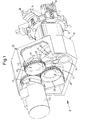
- stepper gear 10 for driving a tool turret 12 shown
- the six switching positions has and accordingly with six tool holders 14 for one turning tool 16 or one or more drills 18 or other processing tools.
- the stepping gear 10 has a housing 20, for example attached to an upper slide of a cross slide arrangement can be.
- a selector shaft 22 by means of tapered roller bearings 24 rotatably mounted about a switching axis S.
- the Switch shaft 22 carries the tool turret 12 and is a hollow shaft formed in which a drive shaft 26 for rotationally driven Tools, for example the drill shown in Fig.1 18, is stored.
- the drive shaft 26 is in the usual way via a reduction gear 28 from a not shown Motor can be driven.
- the left end area in Fig. 1, 3 and 4 the control shaft 22 is a roller carrier 30 with three in the same Angular distances of 120 ° arranged around the switching axis S. Pin 32 formed.
- roller 34 there is 32 on each of the three pins a roller 34 about a roller axis R parallel to the switching axis S. rotatably mounted.
- the three rollers 34 are equidistant from each other the switching axis S and lie in a row, i.e. they are interchangeable by rotating the control shaft 22.
- Axle stub 36 and 36 'mounted which has a small eccentricity have and by means of a clamping plate 38 in a selected Angular position can be clamped.
- On the two stub axles 36 and 36 ' is a cam 40 and 40' by one axis of rotation parallel to the switching axis S and to the roller axes R. K or K 'rotatably mounted.
- the exact location of the axes of rotation K and K ' can be turned by turning the associated eccentric stub shaft Set 36 or 36 'and then fix fix the associated clamping plate 38.
- Each of the two Cam 40 and 40 ' has a substantially circular Core 42 or 42 'of the same measured in the axial direction Width as the rollers 34 and one protruding radially outwards Half-width projection 44 or 44 '.
- the cam plate 40 is shown individually. It is symmetrical with respect to a central plane M. Its core 42 has a leading or when rotating in the direction of the arrow front holding section a, which is exactly circular cylindrical and has the axis of rotation K as the axis of curvature. The holding section a ends at a point b from which the core 42 gradually rises decreasing distance from the axis of rotation K, so that there a central depression c begins. According to the symmetry to the The center plane M increases the distance from the axis of rotation K up to gradually to a position d, and this is followed by further circular cylindrical holding section e. Connects to that the projection 44 with a range of motion that with a steep front flank f begins to form a circular cylindrical shape Section g continues and in a steep rear Edge h ends.
- the cam disk 40 ' is complete with the cam disk 40 the same, but attached to their stub shaft 36 'so that its projection 44 'according to FIGS. 1, 4 and 5 is arranged on the left, while the projection 44 of the cam plate 40 is on the right.
- the protrusions 44 and 44 'overlap each other can be moved past each other, although the two cams 40 and 40 'as a whole are not axially offset from one another are.
- Each of the two cams 40 and 40 ' is with one associated axis of rotation K or K 'concentric intermediate gear 46 or 46 'connected to a common rotation.
- the two idler gears 46 and 46 ' are the same size and in the example shown designed as spur gears; they comb with one of the same size Drive wheel 48, the axis of which bisects an angle Level W lies, which contains the switching axis S and of which two axes of rotation K and K 'of the cam discs 40 and 40' the same is far away.
- the drive wheel 48 is driven by a drive 50, for example an oil motor, driven; in the illustrated Example, this happens in that the drive wheel 48 with a hollow shaft 52 is integrally formed, which by means of a Clamping device 54 with the shaft 56 of the drive 50 transmitting torque connected is.
- a drive 50 for example an oil motor
- the roller carrier 30, and thus also the tool turret 12 rotated step by step by 60 ° and shut down so safely and precisely in the standstill phases, that there is an additional locking of the tool turret 12 is not required, although it can be expected that the Use of certain tools, for example the one shown Turning tool 16, significant torques on the tool turret 12, and thus also act on the roller carrier 30.
- both cam disks 40 and 40 'each have one circular-cylindrical holding section a or e of its core 42 or 42 'on one and the same roller 34 and practice on them each a force F or F ', the line of action of which is considerable Distance from the switching axis S. So it is proportionate low forces F and F 'to each other on the roller carrier 30 exert opposite torques that are sufficient around the tool turret 12 with all occurring loads with certainty to prevent any rotation.
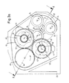
- the said Roller 34 is in a position in which its roller axis R in the bisecting plane W. Now the drive 50 turned on so that the two cams 40 and 40 'over the drive wheel 48 in the same direction as that shown Arrows are rotated, the roller carrier 30 initially still remains in its position.
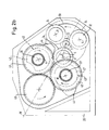
- the two cams 40 and 40 'each have one Position where they started, the roller carrier 30 accelerate in the direction of the arrow; the cam plate 40 acts with the steep front flank f of its projection 44 on the called roller 34, while the trough c in the core 42 'of the cam 40 'of the same role offers 34 space, but at the same time it prevents it from moving away from the cam 40.
- the aforementioned roller 34 thus remains between the two Cam 40 and 40 'positively held during the roller carrier 30 from its initial position Has rotated angle ⁇ .
- the mentioned roller 34 is only removed from the cam 40 ', namely by its core 42', after the roller carrier 30 from its initial position Has rotated angle ⁇ 1.
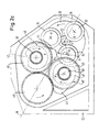
- the cam 40 lies with the steep rear flank h of its projection 44 on the next, now top, roller 34 on and slows the rotation of the roller carrier 30, and thus the tool turret 12.
- This contact of the projection 44 on the upper roll in Fig.2c 34 has started before the previous one, now located at the bottom left Roller 34 has lost contact with the projection 44.
- the roller carrier 30 is thus from the two cams 40 and 40 'continuously positively guided so that he cannot turn uncontrolled even in the deceleration phase.
- the next switching step begins.
- the stepping gear 10 arrives at the in Fig. 2e and Fig. 2f finally shown positions again in the starting position according to FIG. 2a.
- the roll diameter dimensioned relatively large As for six switching steps of the roller carrier 30 only in total rei 34 rolls are required, the roll diameter dimensioned relatively large, and thus the surface pressures be kept low even under the influence of large forces.
Landscapes
- Engineering & Computer Science (AREA)
- Mechanical Engineering (AREA)
- General Engineering & Computer Science (AREA)
- Transmission Devices (AREA)
- Machine Tool Positioning Apparatuses (AREA)
Description
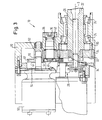
- Fig. 1
- ein erfindungsgemäßes Schrittgetriebe in perspektivischer Ansicht bei geöffnetem und teilweise aufgebrochen dargestelltem Gehäuse,
- Fig.2a
- die axiale Ansicht in Richtung des Pfeils II in Fig.1 während einer ersten Stillstandsphase des Getriebes,
- Fig.2b
- die entsprechende Ansicht während einer ersten Beschleunigungsphase,
- Fig.2c
- die entsprechende Ansicht während einer ersten Verzögerungsphase,
- Fig.2d
- die entsprechende Ansicht während einer zweiten Stillstandsphase,
- Fig.2e
- die entsprechende Ansicht während einer zweiten Beschleunigungsphase
- Fig.2f
- die entsprechende Ansicht während einer zweiten Verzögerungsphase,
- Fig.3
- den Schnitt III-III in Fig.2a.
- Fig.4
- den Schnitt IV-IV in Fig.2d
- Fig.5
- eine axiale Ansicht einer Kurvenscheibe und
- Fig.6
- die Seitenansicht in Richtung des Pfeils VI in Fig.5.
Claims (5)
- Schrittgetriebe, insbes. zum Schalten eines Revolvers (12) an einer Werkzeugmaschine, mitdadurch gekennzeichnet, daßeinem Rollenträger (30), der um eine Schaltachse (S) drehbar ist, und an dem Rollen (34) in Winkelabständen rings um die Schaltachse (S) derart gelagert sind, daß ihre Positionen durch Drehen des Rollenträgers (30) gegeneinander austauschbar sind,zwei Kurvenscheiben (40, 40'), die um je eine eigene Drehachse (K, K') drehbar gelagert und gleichsinnig drehantreibbar sind, und von denen jede gebildet ist voneinem Kern (42, 42'), der einen zur Drehachse (K, K') der betreffenden Kurvenscheibe (40, 40') konzentrischen Haltebereich (a, e) und eine Mulde (c) aufweist, undeinem Vorsprung (44, 44'), der einen Bewegungsbereich (f, h) aufweist, und miteiner Anordnung der Kurvenscheiben (40, 40') in bezug auf den Rollenträger (30), bei derdie Haltebereiche (a, e) beider Kurvenscheiben (40, 40') gleichzeitig und einander entgegenwirkend an je eine Rolle (34) anlegbar sind, wodurch der Rollenträger (30) am Vorwärts- und Rückwärtsdrehen gehindert ist (Fig. 2d), undder Bewegungsbereich (f, h) jeweils einer der Kurvenscheiben (40, 40') an eine der Rollen (34) anlegbar ist, während eine andere der Rollen (34) in die Mulde (c) der anderen Kurvenscheibe (40', 40) eintaucht, so daß der Rollenträger (30) gedreht wird,die Kurvenscheiben (40, 40') einander derart benachbart angeordnet und ihre Vorsprünge (44, 44') einander überlappend derart aneinander vorbei bewegbar sind, daß im Wechsel mit den genannten Anlageverhältnissendie Haltebereiche (a, e) beider Kurvenscheiben (40, 40') gleichzeitig und einander entgegenwirkend an eine und dieselbe Rolle (34) anlegbar sind, wodurch der Rollenträger (30) wiederum am Vorwärts- und Rückwärtsdrehen gehindert ist (Fig. 2a), undder Bewegungsbereich (f, h) jeweils einer Kurvenscheibe (40, 40') an eine der Rollen (34) anlegbar ist, während dieselbe Rolle (34) in die Mulde (c) der anderen Kurvenscheibe (40', 40) eintaucht, so daß der Rollenträger (30) wieder gedreht wird (Fig. 2b, Fig. 20c).
- Schrittgetriebe nach Anspruch 1,
dadurch gekennzeichnet, daß nur der Kern (42, 42') jeder der Kurvenscheiben (40, 40') in seiner axialen Breite und Lage ungefähr mit den Rollen (34) übereinstimmt, während die Vorsprünge (44, 44') in axialer Richtung je ungefähr halb so breit und entsprechend axial gegeneinander versetzt sind. - Schrittgetriebe nach Anspruch 1 oder 2,
dadurch gekennzeichnet, daß jede der Kurvenscheiben (40, 40') in bezug auf eine axiale Mittelebene (M) symmetrisch ist, wobei ihr Haltebereich (a, e) unterteilt ist in einen vorderen Halteabschnitt (a) und einen hinteren Halteabschnitt (e), die einerseits durch die Mulde (c) und andererseits durch den Bewegungsbereich (f, h) miteinander verbunden sind. - Schrittgetriebe nach Anspruch 3,
dadurch gekennzeichnet, daß die beiden Kurvenscheiben (40, 40') gleich sind und ihre Drehachsen (K, K') von der Schaltachse (S) gleich weit entfernt sind. - Schrittgetriebe nach einem der Ansprüche 1 bis 4,
dadurch gekennzeichnet, daß die Drehachsen (K, K') der beiden Kurvenscheiben (40, 40') von je einem exzentrisch gelagerten, dreheinstellbaren Achsstummel (36) definiert sind.
Applications Claiming Priority (3)
| Application Number | Priority Date | Filing Date | Title |
|---|---|---|---|
| DE19619809A DE19619809C1 (de) | 1996-05-15 | 1996-05-15 | Schrittgetriebe |
| DE19619809 | 1996-05-15 | ||
| PCT/EP1997/002350 WO1997043565A1 (de) | 1996-05-15 | 1997-05-07 | Schrittgetriebe |
Publications (2)
| Publication Number | Publication Date |
|---|---|
| EP0839294A1 EP0839294A1 (de) | 1998-05-06 |
| EP0839294B1 true EP0839294B1 (de) | 1999-12-22 |
Family
ID=7794506
Family Applications (1)
| Application Number | Title | Priority Date | Filing Date |
|---|---|---|---|
| EP97923013A Expired - Lifetime EP0839294B1 (de) | 1996-05-15 | 1997-05-07 | Schrittgetriebe |
Country Status (5)
| Country | Link |
|---|---|
| US (1) | US5916324A (de) |
| EP (1) | EP0839294B1 (de) |
| JP (1) | JP3142580B2 (de) |
| DE (2) | DE19619809C1 (de) |
| WO (1) | WO1997043565A1 (de) |
Families Citing this family (3)
| Publication number | Priority date | Publication date | Assignee | Title |
|---|---|---|---|---|
| DE29811467U1 (de) * | 1998-05-07 | 1999-09-23 | Expert Maschinenbau Gmbh, 64653 Lorsch | Schrittgetriebe |
| US6662686B2 (en) * | 2002-03-21 | 2003-12-16 | Kwok Hung Chan | Automatic motor-output-redirection system |
| CN110605729B (zh) * | 2019-09-29 | 2023-10-24 | 中建七局安装工程有限公司 | 一种高空自动化作业的机械臂装置 |
Family Cites Families (13)
| Publication number | Priority date | Publication date | Assignee | Title |
|---|---|---|---|---|
| DE1625023A1 (de) * | 1951-01-28 | 1970-02-05 | Cts Corp | Vorrichtung und Verfahren zum Schalten einer Einstellscheibe u.dgl. |
| US2986949A (en) * | 1959-11-27 | 1961-06-06 | Commercial Cam & Machine Co | Indexing cam structure |
| FR1579551A (de) * | 1968-04-02 | 1969-08-29 | ||
| DE1941214B2 (de) * | 1969-08-13 | 1971-09-23 | Schrittschaltwerk insbesondere zum weiterschalten eines werkstuecktraegers an einer maschine zum bedrucken lackieren ausruesten oder etikettieren von tuben huelsen od dgl | |
| DE2218755A1 (de) * | 1972-04-18 | 1973-10-31 | Ferguson Machine | Schrittantrieb |
| GB1351082A (en) | 1972-04-21 | 1974-04-24 | Ferguson Machine | Indexing drive |
| JPS525177U (de) * | 1975-06-27 | 1977-01-13 | ||
| DE2903732C2 (de) | 1979-02-01 | 1982-06-09 | Focke & Co, 2810 Verden | Schrittgetriebe |
| GB2071805B (en) | 1980-03-17 | 1983-07-06 | Shinohara S | Intermittent rotary table |
| EP0277713B1 (de) * | 1987-01-29 | 1991-08-28 | A.E. Bishop & Associates Pty. Limited | Vorrichtung zum Indexieren und Fördern |
| US5386743A (en) * | 1993-07-13 | 1995-02-07 | Industrial Technology Research Institute | Turret indexing device |
| JP3625849B2 (ja) * | 1993-11-26 | 2005-03-02 | 東芝機械株式会社 | テーブル旋回駆動装置 |
| DE29811467U1 (de) | 1998-05-07 | 1999-09-23 | Expert Maschinenbau Gmbh, 64653 Lorsch | Schrittgetriebe |
-
1996
- 1996-05-15 DE DE19619809A patent/DE19619809C1/de not_active Expired - Fee Related
-
1997
- 1997-05-07 JP JP09540484A patent/JP3142580B2/ja not_active Expired - Fee Related
- 1997-05-07 WO PCT/EP1997/002350 patent/WO1997043565A1/de not_active Ceased
- 1997-05-07 US US08/983,222 patent/US5916324A/en not_active Expired - Fee Related
- 1997-05-07 EP EP97923013A patent/EP0839294B1/de not_active Expired - Lifetime
- 1997-05-07 DE DE59700879T patent/DE59700879D1/de not_active Expired - Lifetime
Also Published As
| Publication number | Publication date |
|---|---|
| DE59700879D1 (de) | 2000-01-27 |
| DE19619809C1 (de) | 1997-11-06 |
| JP3142580B2 (ja) | 2001-03-07 |
| EP0839294A1 (de) | 1998-05-06 |
| JPH11500520A (ja) | 1999-01-12 |
| US5916324A (en) | 1999-06-29 |
| WO1997043565A1 (de) | 1997-11-20 |
Similar Documents
| Publication | Publication Date | Title |
|---|---|---|
| EP1961515A1 (de) | Kupplungseinrichtung für Werkzeughalter oder Werkstückspanneinrichtungen | |
| DE68920667T2 (de) | Automatischer Palettenwechsler. | |
| EP0901861A2 (de) | Fliehkraftgesteuertes Senk- und Entgratwerkzeug | |
| DD295700A5 (de) | Freilaufkupplung | |
| DE3990008C1 (de) | ||
| DE102010002190B3 (de) | Vorrichtung zur Aufnahme zumindest einer Materialrolle und ein Verfahren zur Fixierung einer Materialrolle | |
| DE3134970C2 (de) | Werkzeugrevolver | |
| DE2733482C2 (de) | Automatische Werkzeugwechseleinrichtung | |
| DE3018883C2 (de) | Vorrichtung zur axialen Lagesicherung zwischen einem Hohlrad und den Planetenrädern eines Planetengetriebes | |
| DE4235095C2 (de) | Werkzeugrevolver | |
| EP0066122B1 (de) | Differentialgetriebe | |
| EP0416612B1 (de) | Werkzeugrevolver, insbesondere für Drehautomaten, mit Werkzeughalter für drehantreibbare Werkzeuge | |
| DE3346042C2 (de) | ||
| DE69821433T2 (de) | Leistungsgetriebe für Drehbewegungsübertragung | |
| DE1918962A1 (de) | Fraesmaschine zum Bearbeiten gezahnter Werkstuecke,z.B. zum Abfasen der Zahnkanten oder -enden an Zahnraedern | |
| DE2237345C3 (de) | Ausrichtstation für Bleche elektrischer Maschinen an einer automatischen Nutenstanzanlage | |
| DE2229452C2 (de) | Rollenscherenanlage zum Streifenschneiden von Blechband | |
| EP0799663B1 (de) | Werkzeugrevolver, insbesondere für Drehmaschinen | |
| DE19619809C1 (de) | Schrittgetriebe | |
| EP0180050A1 (de) | Antriebsvorrichtung für Werkstückträger von Bearbeitungsmaschinen | |
| DE2343167A1 (de) | Presse | |
| DE2428413A1 (de) | Entgratungsvorrichtung | |
| DE2905631C2 (de) | Walzgerüst mit mindestens einer von einer losen drehbaren Hülse umgebenden Stützwalze | |
| DE2930965A1 (de) | Schaltbarer mehrfachwerkzeughalter fuer werkzeugmaschinen, insbesondere drehmaschinen | |
| DE19803613A1 (de) | Plandrehkopf |
Legal Events
| Date | Code | Title | Description |
|---|---|---|---|
| PUAI | Public reference made under article 153(3) epc to a published international application that has entered the european phase |
Free format text: ORIGINAL CODE: 0009012 |
|
| 17P | Request for examination filed |
Effective date: 19971202 |
|
| AK | Designated contracting states |
Kind code of ref document: A1 Designated state(s): CH DE FR IT LI |
|
| GRAG | Despatch of communication of intention to grant |
Free format text: ORIGINAL CODE: EPIDOS AGRA |
|
| 17Q | First examination report despatched |
Effective date: 19990312 |
|
| GRAG | Despatch of communication of intention to grant |
Free format text: ORIGINAL CODE: EPIDOS AGRA |
|
| GRAH | Despatch of communication of intention to grant a patent |
Free format text: ORIGINAL CODE: EPIDOS IGRA |
|
| GRAH | Despatch of communication of intention to grant a patent |
Free format text: ORIGINAL CODE: EPIDOS IGRA |
|
| GRAA | (expected) grant |
Free format text: ORIGINAL CODE: 0009210 |
|
| ITF | It: translation for a ep patent filed | ||
| AK | Designated contracting states |
Kind code of ref document: B1 Designated state(s): CH DE FR IT LI |
|
| REG | Reference to a national code |
Ref country code: CH Ref legal event code: EP |
|
| REF | Corresponds to: |
Ref document number: 59700879 Country of ref document: DE Date of ref document: 20000127 |
|
| ET | Fr: translation filed | ||
| PLBE | No opposition filed within time limit |
Free format text: ORIGINAL CODE: 0009261 |
|
| STAA | Information on the status of an ep patent application or granted ep patent |
Free format text: STATUS: NO OPPOSITION FILED WITHIN TIME LIMIT |
|
| 26N | No opposition filed | ||
| PGFP | Annual fee paid to national office [announced via postgrant information from national office to epo] |
Ref country code: IT Payment date: 20080524 Year of fee payment: 12 |
|
| PG25 | Lapsed in a contracting state [announced via postgrant information from national office to epo] |
Ref country code: IT Free format text: LAPSE BECAUSE OF NON-PAYMENT OF DUE FEES Effective date: 20090507 |
|
| PGFP | Annual fee paid to national office [announced via postgrant information from national office to epo] |
Ref country code: DE Payment date: 20130529 Year of fee payment: 17 Ref country code: CH Payment date: 20130521 Year of fee payment: 17 |
|
| PGFP | Annual fee paid to national office [announced via postgrant information from national office to epo] |
Ref country code: FR Payment date: 20130607 Year of fee payment: 17 |
|
| REG | Reference to a national code |
Ref country code: DE Ref legal event code: R119 Ref document number: 59700879 Country of ref document: DE |
|
| REG | Reference to a national code |
Ref country code: CH Ref legal event code: PL |
|
| PG25 | Lapsed in a contracting state [announced via postgrant information from national office to epo] |
Ref country code: CH Free format text: LAPSE BECAUSE OF NON-PAYMENT OF DUE FEES Effective date: 20140531 Ref country code: LI Free format text: LAPSE BECAUSE OF NON-PAYMENT OF DUE FEES Effective date: 20140531 |
|
| REG | Reference to a national code |
Ref country code: DE Ref legal event code: R119 Ref document number: 59700879 Country of ref document: DE Effective date: 20141202 |
|
| REG | Reference to a national code |
Ref country code: FR Ref legal event code: ST Effective date: 20150130 |
|
| PG25 | Lapsed in a contracting state [announced via postgrant information from national office to epo] |
Ref country code: DE Free format text: LAPSE BECAUSE OF NON-PAYMENT OF DUE FEES Effective date: 20141202 |
|
| PG25 | Lapsed in a contracting state [announced via postgrant information from national office to epo] |
Ref country code: FR Free format text: LAPSE BECAUSE OF NON-PAYMENT OF DUE FEES Effective date: 20140602 |