EP0838375B1 - Sicherheitsnetzanordnung - Google Patents
Sicherheitsnetzanordnung Download PDFInfo
- Publication number
- EP0838375B1 EP0838375B1 EP97117460A EP97117460A EP0838375B1 EP 0838375 B1 EP0838375 B1 EP 0838375B1 EP 97117460 A EP97117460 A EP 97117460A EP 97117460 A EP97117460 A EP 97117460A EP 0838375 B1 EP0838375 B1 EP 0838375B1
- Authority
- EP
- European Patent Office
- Prior art keywords
- safety net
- winding shaft
- arrangement according
- locking
- housing
- Prior art date
- Legal status (The legal status is an assumption and is not a legal conclusion. Google has not performed a legal analysis and makes no representation as to the accuracy of the status listed.)
- Expired - Lifetime
Links
- 238000004804 winding Methods 0.000 claims description 89
- 230000001133 acceleration Effects 0.000 claims description 6
- 230000000694 effects Effects 0.000 claims description 3
- 230000000903 blocking effect Effects 0.000 description 5
- 230000006835 compression Effects 0.000 description 5
- 238000007906 compression Methods 0.000 description 5
- 238000011161 development Methods 0.000 description 4
- 230000018109 developmental process Effects 0.000 description 4
- 208000027418 Wounds and injury Diseases 0.000 description 3
- 230000015572 biosynthetic process Effects 0.000 description 2
- 230000006378 damage Effects 0.000 description 2
- 230000001419 dependent effect Effects 0.000 description 2
- 238000010586 diagram Methods 0.000 description 2
- 208000036829 Device dislocation Diseases 0.000 description 1
- 206010019196 Head injury Diseases 0.000 description 1
- 230000001447 compensatory effect Effects 0.000 description 1
- 230000006735 deficit Effects 0.000 description 1
- 230000001934 delay Effects 0.000 description 1
- 230000000881 depressing effect Effects 0.000 description 1
- 208000014674 injury Diseases 0.000 description 1
- 238000004519 manufacturing process Methods 0.000 description 1
- 238000005192 partition Methods 0.000 description 1
Images


Classifications
-
- B—PERFORMING OPERATIONS; TRANSPORTING
- B60—VEHICLES IN GENERAL
- B60R—VEHICLES, VEHICLE FITTINGS, OR VEHICLE PARTS, NOT OTHERWISE PROVIDED FOR
- B60R21/00—Arrangements or fittings on vehicles for protecting or preventing injuries to occupants or pedestrians in case of accidents or other traffic risks
- B60R21/02—Occupant safety arrangements or fittings, e.g. crash pads
- B60R21/06—Safety nets, transparent sheets, curtains, or the like, e.g. between occupants and glass
Definitions
- Safety nets are known from practice, which the Passenger compartment from the loading or trunk of a station wagon mechanically disconnect.
- objects that are in the trunk or trunk of the car be prevented in the event of a rear-end collision in the passenger compartment to be hurled.
- the safety net has that Task to hold the objects back to a hazard to exclude the passengers.
- the safety net by no means fail with delays for which the crumple zone of a vehicle is designed. It is ultimately unsatisfactory if, for example, the driver of the restraint systems and the crumple zone against life-threatening Injury is protected, on the other hand but gets fatal head injuries taught by one Object that in the rear-end collision from the hold is thrown against the driver's head.
- the safety net Since at least in today's motor vehicles the rear seats can be folded down in order to enlarge the load space the safety net is not only Back seat back, but at least also after Front seat backrest folded down required.
- the lower edge of the safety net is on the height of the upper edge of the upright seat back and another case near the floor e.g. in the footwell in front of the Rear seats.
- the distance between the lower attachment point of the safety net and the Headlining different.
- Providing different safety nets is unsatisfactory. That is why it has been in the past tries to open the safety net, similar to a roller blind wind up a winding shaft and just extend the part, the one to separate the cargo area from the Passenger compartment is needed.
- DE 27 49 560 A is a safety net or Partition grid known, the rotatably mounted winding shaft has with the help of a spring motor in the winding direction is biased. The real thing is on the winding shaft Safety net attached, the other edge with a Drawbar is provided below the headlining to be anchored in the vehicle.
- a ratchet wheel is rotatably connected to the winding shaft, that with a pawl in the form of a spring lever cooperates, which is designed as a leaf spring and in engages the recesses of the ratchet wheel.
- the safety net must be retracted the lever by hand in a release or release position be transferred in which the ratchet wheel is unimpeded can rotate.
- the spring lever be locked in the disengaged position in order to to enable a retraction of the safety net. at The spring lever is in the extended position again lifted again and the lever is able to retract to block.
- the safety net can also for the application with full extension so long be designed so that it is still a full extract or two gears around the winding shaft to anchor it to protect the safety net in the winding shaft.
- a spring motor device arranged in the winding shaft keeps the safety net taut in every position as it the winding shaft in the sense of winding up the safety net biases. Keeping the safety net tight shortens the response time in the event of danger.
- the locking device of the new safety net arrangement has two operating states.
- the winding shaft In one of the two Operating states, the winding shaft is essentially free rotatable, in both directions of rotation of the winding shaft, while in the other state there is rotation of the winding shaft is blocked at least in the development sense.
- the locking device can do this be a one-way lock that is like a kind of freewheel works, regardless of any manipulation when taking out the safety net on a winding up the winding shaft is possible.
- the one-way lock can be disabled.
- In the safety net can handle this condition without hindrance for the purpose of hanging in the body from the housing be pulled out.
- a control device is expediently assigned to the blocking device, by means of which the blocking device can be switched back and forth between the two states.
- This control device can be operated manually, it can be dependent on the vehicle acceleration or -working delay or it can be started by excessive acceleration of the winding shaft which occurs when an object is thrown into the safety net.
- At least two locking devices are provided. These locking devices are provided at one end of the winding shaft. These locking devices there can work according to the same or different working principles. It's even in the spirit of improving security conceivable to use three locking devices, wherein two locking devices arranged at one end of the winding shaft are and work according to different principles, while at the other end the third locking device sits, which in turn is of a different design.
- Control device by vehicle acceleration is unlocked and the locking device in the locked state transferred.
- Such two similar locking devices can be accommodated at both ends of the winding shaft his. It is also possible to use only one such locking device to use while on the other side of the winding shaft a locking device sits, which thereby activates is that an object hurled into the safety net causes a lateral force on the winding shaft, whereby the winding shaft from its storage position in which it is free is rotatable, is lifted into a position in which the rotation is blocked. It is possible to continue in place manual operation is a fully automatic operation provided.
- the locking device preferably has a Winding shaft essentially rotatably connected locking member on which cooperates with a locking member in the housing.
- the locking member is a non-rotatably connected to the winding shaft Ratchet wheel that has ratchet teeth over the entire circumference wearing.
- the locking member can also be a disc be that only has one or two teeth and the opposite the winding shaft is radially movable.
- Pawls come into question as locking elements, Gate valve or hollow gears fixed in the housing, which are either fully equipped with ratchet teeth or wear just a few ratchet teeth.
- the control device comprises one mounted in a trough Bullet accelerating out of the trough is deflected and causes a corresponding actuation.
- the control device can also be an inertial system be connected to the winding shaft.
- the control device can also be operated by a Latching device or deformable means can be formed become effective when transverse forces act on the winding shaft and the winding shaft in the associated storage facility move radially.
- Fig. 1 illustrates one not shown Combi car whose backrest 1, on the back 2 in near the top of the backrest 1 a safety net arrangement 3 is anchored releasably.
- the representation corresponds here a point of view from the perspective of the open Load compartment flap of the station wagon concerned.
- the safety net arrangement 3 includes an elongated one Housing 4 that extends across the width of the rear seat back 1 stretches and at its top with a smooth-edged Outlet slot 5 is provided.
- the outlet slot 5 extends from one end cap 6 to the opposite other end cap 7 of the housing 4th
- the housing 4 serves Bearing of a winding shaft 8 on the one edge Safety net 9 is attached, through the slot 5 can be pulled out of the housing 4.
- One to the winding shaft 8 parallel edge 11 of the safety net 9 is one Loop 12 formed through which an extension rod 13 passes through at both ends with mushroom-like heads 15 is provided, which in corresponding receiving pockets to be hung on the roof of the car in question.
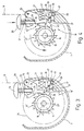
- the housing 4 In the housing 4 are for the right and the left 8 locking devices 16 arranged at the end of the winding shaft, their structure and mode of operation based on the principle diagrams 3 and 4 or 5 and 6 is explained.
- the winding shaft 8 goes into one at its right end Shafts tap 17, which from a thinner section 18th and a thicker section 19.
- the thinner shaft section 18 is in a not shown, slide bearing located in the end cap 7.
- the locking device 16 ' With the Section 19 with a larger diameter acts the locking device 16 'together, which consists of a with the winding shaft 8 rotatably connected locking member 21 'and a so cooperating locking member 22 ', which in the end cap 7 is pivotally mounted.
- the locking member 21 ' has the shape of a locking gear, that sits rotatably on the section 19 and with a A large number of sawtooth-shaped locking teeth 23 'is provided.
- the ratchet teeth 23 ' point counterclockwise and thus in the development direction of the safety network 9, which on the Winding shaft 8 wound bale 24 illustrated in phantom is.
- the locking member is a locking pawl 22 'which can be pivoted axially parallel to the winding shaft 8 at 25 is stored. She carries on her from the swivel axis 25 remote end of a pawl nose 26, which cooperate is designed with the locking teeth 23 '. With With the help of a compression spring 27 designed as a coil spring is the locking pawl 22 'in the engaged position biased with the ratchet wheel 21 '.
- an actuating button 28 is provided, one actuating head 29 and one attached to it has cylindrical shaft 31.
- the shaft 31 is the actuation button 28 in a cylindrical bore 32 guided next to the pivot axis 25.
- One on the shaft 31 sitting coil spring 33 is supported on the outside the cap 7 and is at the other end at the bottom of the Head 29 to the actuating button 28 upwards in the direction to bias away from the locking pawl 22 '.
- the actuation button 28 stands with his from the head 29 distal end 34 of the shaft 31 on a step or Shoulder 35 on the locking pawl 22 'in the area between the pivot axis 25 and the locking lug 26 is formed.
- the locking pawl 22 ' is provided with a hook 36, which is set up with a hook 37 of a two-armed Control lever 38 cooperate.
- the hook 36 opens in the opposite direction as the hook 37.
- the two-armed control lever 38 is axially parallel at 39 to the winding shaft 8 in the cap 7 and pivoted is with the help of a compression spring 41, which is below the Hook 37 is in the engaged position with the hook 36 preloaded.
- a compression spring 41 which is below the Hook 37 is in the engaged position with the hook 36 preloaded.
- the two hooks 36 and 37 are over Inclined surfaces 42 and 43 to each other; they are not in each other hooked.
- the control lever 38 is on its remote from the hook 37 End with an extension 44 pointing downwards provided which contains a trough 45 which extends downwards opens.
- a trough 46 in corresponds to the trough 45 the end cap 7. Between the two troughs 45 and 46 is a ball 47 acting as a control member bound.
- the locking device 16 "on the left side of the winding shaft 8 differs from the locking device 16 ' on the right side.
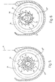
- the structure is shown in a schematic diagram Fig. 5. Here are functionally equivalent to each other Parts with the same reference number supplemented by two Designated apostrophes.
- the winding shaft 8 with a Bearing pin 17 "provided, which comes from the thicker section 19 "and the thin section 18".
- the locking member 21 sits in turn in the form of a ratchet gear with ratchet teeth 23 ", so are aligned so that they oppose the unwinding direction.
- Bearing bush 48, 49 on an inner end face the end cap 6 is integrally formed. This bearing bush 48 points in the direction of the adjacent winding shaft 8.
- a section 50 is on the circumference of the bearing bush 48 through two predetermined breaking points 51 in the form of two in parallel delimited notches, the Distance corresponds approximately to the diameter of the journal 18 and run through the length of the bearing bush 48. Their exact location follows from the below given functional description.
- the locking member 22 "of the locking device 16" on left end consists of a ring gear that rotates in the Housing 4 is anchored and is coaxial with the bearing bush 48.
- This ring gear 22 " is provided with three locking teeth 52, which is the section bounded between the two notches 51 50 of the bearing bush 48 are approximately opposite.
- the Tooth tip diameter of the ratchet 23 " is smaller than the tooth tip diameter of the ring gear 22 ", which Ratchet wheel 23 "with uninjured bearing bush 48 freely rotatable is.
- the predetermined breaking points are in the form of delivery of the two notches 51 intact, in the sense that the bearing sleeve 48 with its cylindrical contained therein Bore a plain bearing for the shaft journal in question 18 "forms.
- the locking device 16 'on the right side of the Winding shaft 8 may be in the state shown in FIG. 3 are located. In this state, the locking pawl engages 22 'in a tooth gap between locking teeth 23' of the associated Ratchet wheel 21 '. This is a rotation of the Winding shaft 8 in the sense of pulling out the safety net 9 blocked from the housing 4. To the safety net 9 to be able to pull out, the user presses Control button 28 low, causing the locking pawl 22 'against the action of the compression spring 27 in Counterclockwise pivoted about the pivot axis 25 a bit becomes. The hook presses during this swiveling movement 36 the hook 37 against the action of the compression spring 41st back down.
- the user can now freely access the safety net 9 Pull out of the housing 4 as far as necessary is so that the tie rod 13 in the body side Anchors can be hung.
- the locking device 16 prevents by the engagement between the ratchet wheel 21 'and the locking lug 26 such a rotation at the right end of the Winding shaft 8.
- the winding shaft 8 can no longer turn, calls the object pressing against the safety net 9 on the Winding shaft 8 a significant lateral force.
- the lateral force leads to that on the left side of the winding shaft 8th the bearing bush 48 breaks open at the two notches 51 and the part 50 of the bearing bush 48 located therebetween pushes away at the top.
- the shaft journal 18 "slips upwards the bearing sleeve 48, which is now open at the top, whereby the ratchet teeth 23 "of this ratchet wheel 21 located there" can come into engagement with the locking teeth 52.
- the winding shaft 8 is at both ends blocked against rotation and can safely against the safety net 9 hold back pressing object.
- the security network arrangement 3 On the Rear seat back 1 attached, but e.g. in the footwell in front of the Rear seat.
- This assembly requires because of the larger Distance a much greater length of safety net, but which is available on the winding shaft 8.
- the Handling the safety network arrangement 3 is in principle the same, as well as blocking in a rear-end collision.
- control button acts on the right side 28 together with the control lever 38 as manual / acceleration-dependent Control device to the locking device Hold 16 'in the freewheel position.
- the locking device 16 "on the left hand side is controlled by lateral force, the control device the two predetermined breaking notches 51 are that when a given shear force is exceeded let the bearing bush 48 break open so that the locking member 21 "can engage with the locking member 22".
- Locking device 16 on the right in her Rest position is in the locked position in which a turning the winding shaft 8 is blocked in the unwinding direction.
- the Locking device 16 on the left hand side has one Rest position that corresponds to the freewheel position. Only in the event of an accident is the locking device moved into the Locked position transferred.
- locking device 16 can also be used there the locking device 16 'shown in FIGS. 3 and 4 for Come into play.
- a security network arrangement has one in a housing freely rotatable winding shaft on which with an edge a safety net is attached.
- the safety net leads out of the housing through an outlet slot, the outer edge being connected with a tension rod is.
- the winding shaft are preferably at both ends Assigned locking devices that prevent objects, in the event of a rear-end collision into the safety net to be flung, the safety net with balloon formation unwind from the winding shaft. You can different locking devices used at both ends become. These locking devices can vary depending on the application and ease of use and manufacturing costs be designed so that they are at rest enable a free running of the winding shaft and only at a strong deceleration of the vehicle or a strong one Angular acceleration of the winding shaft can be activated.
Landscapes
- Engineering & Computer Science (AREA)
- Mechanical Engineering (AREA)
- Vehicle Step Arrangements And Article Storage (AREA)
Description
-verzögerung arbeiten oder sie kann durch eine übermäßige Beschleunigung der Wickelwelle in Gang gesetzt werden, die auftritt, wenn ein Gegenstand in das Sicherheitsnetz geschleudert wird. Schließlich ist es denkbar, die Steuereinrichtung durch eine Querkraft, die auf die Wickelwelle einwirkt, zu aktivieren.
Claims (15)
- Sicherheitsnetzanordnung (3) für Kraftfahrzeuge, insbesondere für Kombi-PKW, um bei einem Auffahrunfall Gegenstände aus einem Koffer- oder Gepäckraum daran zu hindern, in den Fahrgastraum geschleudert zu werden,
mit einem Gehäuse (4), das einen parallel zu der Länge des Gehäuses (4) sich erstreckenden Auslaufschlitz (5) aufweist,
mit einer in dem Gehäuse (4) drehbar gelagerten Wickelwelle (8),
mit einem Sicherheitsnetz (9), das zwei voneinander beabstandete Längskanten (11) aufweist, von denen eine an der Wickelwelle befestigt ist und die andere (11) mit einem Zugstab (13) verbunden ist, und das durch den Auslaufschlitz (5) verläuft,
mit einer der Wickelwelle (8) zugeordneten Wickeleinrichtung, um die Wickelwelle (8) im Sinne eines Aufwickelns des Sicherheitsnetzes (9) in Umdrehungen zu versetzen,
mit wenigstens einer einen Ruhezustand aufweisenden Sperreinrichtung (16), die zwischen dem Ruhezustand und einem weiteren Zustand umschaltbar ist, wobei sie in dem Ruhezustand eine Rotation der Wickelwelle (8) infolge der Wirkung eines in das Sicherheitsnetz (9) geschleuderten Gegenstands im Sinne des Abwickelns des Sicherheitsnetzes (9) sperrt, und in dem anderen Zustand die Wickelwelle (8) im wesentlichen frei drehbar ist, und
mit einer Steuereinrichtung (29,38,47;50,51;72,84), die der Sperreinrichtung (16) zugeordnet ist und durch die die Sperreinrichtung (16) aus dem einen Zustand in den Ruhezustand umschaltbar ist. - Sicherheitsnetzanordnung nach Anspruch 1, dadurch gekennzeichnet, daß zu der Wickeleinrichtung eine Federmotoreinrichtung gehört, durch die die Wickelwelle (8) in Sinne des Aufwickelns des Sicherheitsnetzes (9) vorgespannt ist.
- Sicherheitsnetzanordnung nach Anspruch 1, dadurch gekennzeichnet, daß die Sperreinrichtung (16) ein Ein-Richtungs-Gesperre ist, das im Sperrzustand eine Drehung der Wickelwelle (8) im Sinne des Aufwickeins des Sicherheitsnetzes (9) nicht verhindert.
- Sicherheitsnetzanordnung nach Anspruch 1, dadurch gekennzeichnet, daß die Steuereinrichtung (29,38,47) zur manuellen Betätigung eingerichtet ist.
- Sicherheitsnetzanordnung nach Anspruch 1, dadurch gekennzeichnet, daß die Steuereinrichtung (29,38,47;72,84) derart gestaltet ist, daß sie in Abhängigkeit von der Beschleunigung des Fahrzeugs wirksam zu machen ist.
- Sicherheitsnetzanordnung nach Anspruch 1, dadurch gekennzeichnet, daß sie wenigstens zwei unterschiedliche Sperreinrichtungen (16) aufweist.
- Sicherheitsnetzanordnung nach Anspruch 1, dadurch gekennzeichnet, daß die Sperreinrichtung (16) wenigstens ein im wesentlichen drehfest mit der Wickelwelle (8) verbundenes Sperrglied (21,67) aufweist, das mit einem in dem Gehäuse (4) befindlichen Verriegelungsglied (22,62) zusammenwirkt.
- Sicherheitsnetzanordnung nach Anspruch 7, dadurch gekennzeichnet, daß das Sperrglied ein drehfest mit der Wickelwelle (8) verbundenes Sperrad (21) aufweist, das eine Verzahnung trägt, die sich über den gesamten Umfang fortsetzt.
- Sicherheitsnetzanordnung nach Anspruch 8, dadurch gekennzeichnet, daß die Verzahnung sägezahnförmig ist.
- Sicherheitsnetzanordnung nach Anspruch 7, dadurch gekennzeichnet, daß das Verriegelungsglied von einer in dem Gehäuse (4) schwenkbar gelagerten Verriegelungsklinke (22) gebildet ist.
- Sicherheitsnetzanordnung nach Anspruch 7, dadurch gekennzeichnet, daß das Verriegelungsglied von einem in dem Gehäuse (4) verschiebbar gelagerten Verriegelungsschieber gebildet ist.
- Sicherheitsnetzanordnung nach Anspruch 7, dadurch gekennzeichnet, daß das Verriegelungsglied von wenigstens einem in dem Gehäuse (4) starr befestigten Verriegelungszahn (52,63) gebildet ist.
- Sicherheitsnetzanordnung nach Anspruch 7, dadurch gekennzeichnet, daß das Verriegelungsglied von einem in dem Gehäuse (4) drehfest sitzenden Hohlrad (22,62) gebildet ist, das wenigstens einen Verriegelungszahn (52) oder eine Vielzahl äqudistant verteilter Verriegelungszähne (63) trägt.
- Sicherheitsnetzanordnung nach Anspruch 1, dadurch gekennzeichnet, daß zu der Steuereinrichtung (29,38,47;72,84) eine in einer Mulde (45,46) gelagerte Kugel (47,84) gehört.
- Sicherheitsnetzanordnung nach Anspruch 1, dadurch gekennzeichnet, daß zu der Steuereinrichtung (29,38,47) eine in dem Gehäuse (4) schwenkbar gelagerte Klinke (38) gehört.
Applications Claiming Priority (2)
| Application Number | Priority Date | Filing Date | Title |
|---|---|---|---|
| DE19643691 | 1996-10-23 | ||
| DE19643691A DE19643691C2 (de) | 1996-10-23 | 1996-10-23 | Sicherheitsnetzanordnung |
Publications (2)
| Publication Number | Publication Date |
|---|---|
| EP0838375A1 EP0838375A1 (de) | 1998-04-29 |
| EP0838375B1 true EP0838375B1 (de) | 2002-04-10 |
Family
ID=7809530
Family Applications (1)
| Application Number | Title | Priority Date | Filing Date |
|---|---|---|---|
| EP97117460A Expired - Lifetime EP0838375B1 (de) | 1996-10-23 | 1997-10-09 | Sicherheitsnetzanordnung |
Country Status (3)
| Country | Link |
|---|---|
| US (1) | US5971433A (de) |
| EP (1) | EP0838375B1 (de) |
| DE (2) | DE19643691C2 (de) |
Families Citing this family (36)
| Publication number | Priority date | Publication date | Assignee | Title |
|---|---|---|---|---|
| US5772370A (en) | 1995-11-22 | 1998-06-30 | Moore; Donal | Retractable and/or removable net type cargo restraining system |
| US6817644B2 (en) | 1995-11-22 | 2004-11-16 | Exco Automotive Solutions, L.P. | Load retaining barrier net for motor vehicle |
| JPH1024790A (ja) * | 1996-07-11 | 1998-01-27 | Ashimori Ind Co Ltd | 車両用巻取式荷崩れ防止装置 |
| JP2001505159A (ja) * | 1996-12-06 | 2001-04-17 | バウマイスター・ウント・オストラー・ゲーエムベーハー・ウント・コンパニー | 取扱いが簡単な安全ネット装置 |
| DE19708192C5 (de) * | 1997-02-28 | 2006-08-03 | Bos Gmbh & Co. Kg | Laderaum-Trennvorrichtung für Kraftwagen, insbesondere für Kombinations-Personenkraftwagen |
| JP3784421B2 (ja) * | 1998-01-05 | 2006-06-14 | 芦森工業株式会社 | 車両用巻取式パーティショニングシステム |
| DE19818583C1 (de) * | 1998-04-25 | 1999-09-23 | Bayerische Motoren Werke Ag | Kraftfahrzeug mit mindestens einem zwischen Fahrgastraum und Laderaum anbringbaren Rollo |
| DE19843044B4 (de) * | 1998-09-19 | 2007-06-28 | Volkswagen Ag | Ladegutrückhaltevorrichtung für ein Kraftfahrzeug |
| SE514565C2 (sv) * | 1999-07-15 | 2001-03-12 | Klippan Safety Ab | Kojarrangemang i en lastbilshytt |
| DE19946382A1 (de) * | 1999-09-28 | 2001-04-12 | Baumeister & Ostler Gmbh Co | Laderaumabtrennung für Kraftfahrzeuge |
| US20020056980A1 (en) | 2000-05-17 | 2002-05-16 | Saczalski Todd K. | Vehicle occupant safety net |
| DE10044958C2 (de) | 2000-09-12 | 2003-04-10 | Bos Gmbh | Schutzvorrichtung zur Sicherung eines Laderaumes in einem Fahrzeuginnenraum |
| DE10046142B4 (de) * | 2000-09-15 | 2006-08-24 | Bos Gmbh & Co. Kg | Vorrichtung zur Festlegung eines Endbereiches einer Fahrzeug- Sicherheitseinrichtung an einem fahrzeugseitigen Befestigungspunkt sowie zur Spannung des Endbereichs der Fahrzeug-Sicherheitseinrichtung relativ zu dem Befestigungspunkt |
| DE10056671C1 (de) * | 2000-11-09 | 2002-06-06 | Bos Gmbh | Trennvorrichtung für ein Kraftfahrzeug |
| GB2370017B (en) * | 2000-12-15 | 2004-07-14 | Brian Marran | Vehicle security gate |
| GB2361462A (en) * | 2001-07-25 | 2001-10-24 | Gordon Stewart Hill | Roller blind for separating load compartments from occupant compartments in vehicles |
| AU2002361612A1 (en) | 2001-11-12 | 2003-05-26 | Polytech Netting, L.P. | Frameless load restraining vehicular barrier device |
| DE10229815B4 (de) * | 2002-06-28 | 2006-12-14 | Bos Gmbh & Co. Kg | System zum Laderaumschutz von Fahrzeugen |
| US6749241B1 (en) | 2002-08-29 | 2004-06-15 | Collins & Aikman Products | Vehicle cargo panel having retractable belt |
| US20050023312A1 (en) * | 2003-08-01 | 2005-02-03 | Steinberg Judith Lynn | Cargo restraint and storage device and method |
| DE10356911B3 (de) * | 2003-12-02 | 2005-01-20 | Bos Gmbh & Co. Kg | Laderaumschutzvorrichtung für ein Kraftfahrzeug |
| US7637705B2 (en) * | 2004-02-27 | 2009-12-29 | Valeda Company | Track fitting with visual indicia of engagement |
| US7229238B2 (en) * | 2004-03-25 | 2007-06-12 | Valeda Company Llc | Wheelchair docking system |
| SE527806C2 (sv) * | 2005-03-04 | 2006-06-13 | Volvo Lastvagnar Ab | Säkerhetsnät |
| DE102006001029B3 (de) * | 2006-01-02 | 2007-05-31 | Bos Gmbh & Co. Kg | Schutzvorrichtung für ein Kraftfahrzeug |
| DE102006018079B3 (de) * | 2006-04-11 | 2007-11-22 | Bos Gmbh & Co. Kg | Laderaum für ein Kraftfahrzeug mit einer Schutzvorrichtung |
| FR2907399A1 (fr) * | 2006-10-18 | 2008-04-25 | Wagon Sas | Dispositif de separation a deploiement et maintien automatique,et vehicule automobile correspondant |
| US7931177B2 (en) * | 2007-08-14 | 2011-04-26 | Bos Gmbh & Co. Kg | Storage container for use in a boot |
| DE102007045037A1 (de) * | 2007-09-13 | 2009-04-02 | Bos Gmbh & Co. Kg | Vorrichtung zum Verstauen von Gegenständen in einem Kraftfahrzeug |
| DE102007058255B3 (de) * | 2007-11-26 | 2009-07-02 | Bos Gmbh & Co. Kg | Staufach mit Tragrahmen und Aufnahmevorrichtung für einen Tragrahmen |
| TW201114629A (en) * | 2009-10-28 | 2011-05-01 | Macauto Ind Co Ltd | Vehicle safety protection device |
| US9333931B1 (en) * | 2015-01-28 | 2016-05-10 | Ford Global Technologies, Llc | Passenger protection system |
| DE102016116775C5 (de) * | 2016-09-07 | 2023-07-13 | Macauto Industrial Co., Ltd. | Laderaumtrennnetz mit Auszugsbegrenzung |
| US10611314B2 (en) * | 2017-09-29 | 2020-04-07 | Faurecia Automotive Seating, Llc | Vehicle privacy screen |
| US11286048B2 (en) * | 2019-02-11 | 2022-03-29 | The Boeing Company | Aircraft cargo restraint system and method for restraining cargo within an aircraft |
| WO2020252253A1 (en) * | 2019-06-12 | 2020-12-17 | Shanghai Yanfeng Jinqiao Automotive Trim Systems Co. Ltd. | Vehicle component |
Family Cites Families (10)
| Publication number | Priority date | Publication date | Assignee | Title |
|---|---|---|---|---|
| US1186865A (en) * | 1915-04-12 | 1916-06-13 | William A Uttz | Wind-shield protector. |
| US1936251A (en) * | 1932-07-12 | 1933-11-21 | Lester W May | Safety curtain |
| JPS53142728A (en) * | 1977-05-17 | 1978-12-12 | Takata Kojyo Co | Winder device of accelerate speed induction |
| DE2739741A1 (de) * | 1977-09-03 | 1979-03-15 | Daimler Benz Ag | Mit einer einen laderaum verschliessenden hecktuere versehener kraftwagen |
| DE2749560A1 (de) * | 1977-11-05 | 1979-05-10 | Eugen Seitz | Vorrichtung zum abteilen des hinteren laderaumes vom fahrgastraum eines fuer den transport von personen und lasten ausgelegten kraftfahrzeuges (kombifahrzeug) |
| DE2823334C2 (de) * | 1978-05-29 | 1986-08-28 | Autoflug Gmbh, 2084 Rellingen | Selbstsperrender Gurtaufroller für Sicherheitsgurte |
| DE3418378A1 (de) * | 1984-05-17 | 1986-02-13 | Britax-Kolb GmbH & Co, 8065 Erdweg | Gurtaufroller fuer fahrzeugsicherheitsgurte |
| DE4336380C2 (de) * | 1993-10-25 | 1995-08-10 | Baumeister & Ostler Gmbh Co | Sicherheitsnetzanordnung |
| DE4438910C1 (de) * | 1994-11-03 | 1996-03-21 | Butz Peter Verwaltung | Rückhaltevorrichtung für den Laderaum von Kraftfahrzeugen, wie z. B. für Kombinationskraftwagen oder Großraum-Personenkraftwagen |
| DE19531303C1 (de) * | 1995-08-25 | 1997-02-06 | Baumeister & Ostler Gmbh Co | Laderaumabtrennung zwischen einem Fondraum und einem Laderaum eines Innenraumes eines Kombi-Personenkraftwagens |
-
1996
- 1996-10-23 DE DE19643691A patent/DE19643691C2/de not_active Expired - Fee Related
-
1997
- 1997-10-09 DE DE59706950T patent/DE59706950D1/de not_active Expired - Lifetime
- 1997-10-09 EP EP97117460A patent/EP0838375B1/de not_active Expired - Lifetime
- 1997-10-20 US US08/954,509 patent/US5971433A/en not_active Expired - Lifetime
Also Published As
| Publication number | Publication date |
|---|---|
| US5971433A (en) | 1999-10-26 |
| EP0838375A1 (de) | 1998-04-29 |
| DE19643691C2 (de) | 2000-03-23 |
| DE59706950D1 (de) | 2002-05-16 |
| DE19643691A1 (de) | 1998-04-30 |
Similar Documents
| Publication | Publication Date | Title |
|---|---|---|
| DE19643691C2 (de) | Sicherheitsnetzanordnung | |
| EP0640513B1 (de) | Sicherheitsnetzanordnung | |
| DE102012019004B4 (de) | Gurtaufroller für einen Sicherheitsgurt | |
| DE2420848A1 (de) | Fahrzeuginsassenrueckhaltesystem | |
| EP0754594B1 (de) | Abdeckeinrichtung mit hoher Crashsicherheit | |
| DE4307012C2 (de) | Sicherheitsgurt-Retraktor | |
| DE102020107973A1 (de) | Sicherheitsgurtaufrollerbaugruppe | |
| DE2749560A1 (de) | Vorrichtung zum abteilen des hinteren laderaumes vom fahrgastraum eines fuer den transport von personen und lasten ausgelegten kraftfahrzeuges (kombifahrzeug) | |
| DE3009094A1 (de) | Auf traegheitskraefte ansprechende betaetigungsvorrichtung fuer eine im notfall blockierende fahrzeug-sitzgurtrueckholvorrichtung | |
| DE2556400A1 (de) | Einziehvorrichtung fuer sicherheitsgurte | |
| DE19849927C2 (de) | Sicherheitseinrichtung für Fahrzeuge, insbesondere Laderaum-Trennvorrichtung für Kraftwagen, wie zum Beispiel für Kombinations-Personenkraftwagen o. dgl. | |
| DE1158847B (de) | Selbstsperrende Aufwickelvorrichtung fuer einen Anschnallgurt | |
| DE102016116775B3 (de) | Laderaumtrennnetz mit Auszugsbegrenzung | |
| EP0861758B1 (de) | Laderaum-Trennvorrichtung für Kraftwagen, insbesondere für Kombinations-Personenkraftwagen | |
| DE102024125541A1 (de) | Sicherheitsgurtaufroller mit lastbegrenzung | |
| DE1556415C3 (de) | Selbstsperrender Gurtaufroller | |
| DE102023113141A1 (de) | Sicherheitsgurtbaugruppe | |
| DE102018118357A1 (de) | Belastungsbegrenzender sicherheitsgurtaufroller | |
| DE29623739U1 (de) | Sicherheitsnetzanordnung | |
| DE2653369A1 (de) | Armrueckhalteeinrichtung fuer schleudersitze | |
| DE19843044B4 (de) | Ladegutrückhaltevorrichtung für ein Kraftfahrzeug | |
| EP2308722B1 (de) | Laderaumabtrennung | |
| DE10207575A1 (de) | Kfz-Sicherheitseinrichtung, insbesondere Kfz-Sicherheitsnetz | |
| DE2365551C3 (de) | Automatischer Gurtaufroller für Sicherheitsgurte in Fahrzeugen, insbesondere Kraftfahrzeugen | |
| WO2006081851A1 (de) | Sicherheitsgurtvorrichtung |
Legal Events
| Date | Code | Title | Description |
|---|---|---|---|
| PUAI | Public reference made under article 153(3) epc to a published international application that has entered the european phase |
Free format text: ORIGINAL CODE: 0009012 |
|
| AK | Designated contracting states |
Kind code of ref document: A1 Designated state(s): DE FR GB SE |
|
| AX | Request for extension of the european patent |
Free format text: AL;LT;LV;RO;SI |
|
| 17P | Request for examination filed |
Effective date: 19980725 |
|
| AKX | Designation fees paid |
Free format text: DE FR GB SE |
|
| RBV | Designated contracting states (corrected) |
Designated state(s): DE FR GB SE |
|
| 17Q | First examination report despatched |
Effective date: 19991025 |
|
| GRAG | Despatch of communication of intention to grant |
Free format text: ORIGINAL CODE: EPIDOS AGRA |
|
| GRAG | Despatch of communication of intention to grant |
Free format text: ORIGINAL CODE: EPIDOS AGRA |
|
| GRAH | Despatch of communication of intention to grant a patent |
Free format text: ORIGINAL CODE: EPIDOS IGRA |
|
| REG | Reference to a national code |
Ref country code: GB Ref legal event code: IF02 |
|
| RAP1 | Party data changed (applicant data changed or rights of an application transferred) |
Owner name: BOS GMBH & CO. KG |
|
| GRAH | Despatch of communication of intention to grant a patent |
Free format text: ORIGINAL CODE: EPIDOS IGRA |
|
| GRAA | (expected) grant |
Free format text: ORIGINAL CODE: 0009210 |
|
| AK | Designated contracting states |
Kind code of ref document: B1 Designated state(s): DE FR GB SE |
|
| REF | Corresponds to: |
Ref document number: 59706950 Country of ref document: DE Date of ref document: 20020516 |
|
| GBT | Gb: translation of ep patent filed (gb section 77(6)(a)/1977) |
Effective date: 20020708 |
|
| ET | Fr: translation filed | ||
| ET | Fr: translation filed | ||
| PGFP | Annual fee paid to national office [announced via postgrant information from national office to epo] |
Ref country code: SE Payment date: 20021002 Year of fee payment: 6 |
|
| PLBQ | Unpublished change to opponent data |
Free format text: ORIGINAL CODE: EPIDOS OPPO |
|
| PLBI | Opposition filed |
Free format text: ORIGINAL CODE: 0009260 |
|
| PLBF | Reply of patent proprietor to notice(s) of opposition |
Free format text: ORIGINAL CODE: EPIDOS OBSO |
|
| 26 | Opposition filed |
Opponent name: BUTZ-LEPER AUTOMOTIVE GMBH Effective date: 20030110 |
|
| PLAX | Notice of opposition and request to file observation + time limit sent |
Free format text: ORIGINAL CODE: EPIDOSNOBS2 |
|
| PGFP | Annual fee paid to national office [announced via postgrant information from national office to epo] |
Ref country code: GB Payment date: 20030929 Year of fee payment: 7 |
|
| PG25 | Lapsed in a contracting state [announced via postgrant information from national office to epo] |
Ref country code: SE Free format text: LAPSE BECAUSE OF NON-PAYMENT OF DUE FEES Effective date: 20031010 |
|
| PLBD | Termination of opposition procedure: decision despatched |
Free format text: ORIGINAL CODE: EPIDOSNOPC1 |
|
| PLBM | Termination of opposition procedure: date of legal effect published |
Free format text: ORIGINAL CODE: 0009276 |
|
| STAA | Information on the status of an ep patent application or granted ep patent |
Free format text: STATUS: OPPOSITION PROCEDURE CLOSED |
|
| 27C | Opposition proceedings terminated |
Effective date: 20031123 |
|
| EUG | Se: european patent has lapsed | ||
| PG25 | Lapsed in a contracting state [announced via postgrant information from national office to epo] |
Ref country code: GB Free format text: LAPSE BECAUSE OF NON-PAYMENT OF DUE FEES Effective date: 20041009 |
|
| GBPC | Gb: european patent ceased through non-payment of renewal fee |
Effective date: 20041009 |
|
| PGFP | Annual fee paid to national office [announced via postgrant information from national office to epo] |
Ref country code: FR Payment date: 20111103 Year of fee payment: 15 |
|
| REG | Reference to a national code |
Ref country code: FR Ref legal event code: ST Effective date: 20130628 |
|
| PG25 | Lapsed in a contracting state [announced via postgrant information from national office to epo] |
Ref country code: FR Free format text: LAPSE BECAUSE OF NON-PAYMENT OF DUE FEES Effective date: 20121031 |
|
| PGFP | Annual fee paid to national office [announced via postgrant information from national office to epo] |
Ref country code: DE Payment date: 20131031 Year of fee payment: 17 |
|
| REG | Reference to a national code |
Ref country code: DE Ref legal event code: R119 Ref document number: 59706950 Country of ref document: DE |
|
| PG25 | Lapsed in a contracting state [announced via postgrant information from national office to epo] |
Ref country code: DE Free format text: LAPSE BECAUSE OF NON-PAYMENT OF DUE FEES Effective date: 20150501 |