US1936251A - Safety curtain - Google Patents
Safety curtain Download PDFInfo
- Publication number
- US1936251A US1936251A US622144A US62214432A US1936251A US 1936251 A US1936251 A US 1936251A US 622144 A US622144 A US 622144A US 62214432 A US62214432 A US 62214432A US 1936251 A US1936251 A US 1936251A
- Authority
- US
- United States
- Prior art keywords
- curtain
- shaft
- dog
- ratchet
- drums
- Prior art date
- Legal status (The legal status is an assumption and is not a legal conclusion. Google has not performed a legal analysis and makes no representation as to the accuracy of the status listed.)
- Expired - Lifetime
Links
Images


Classifications
-
- B—PERFORMING OPERATIONS; TRANSPORTING
- B60—VEHICLES IN GENERAL
- B60J—WINDOWS, WINDSCREENS, NON-FIXED ROOFS, DOORS, OR SIMILAR DEVICES FOR VEHICLES; REMOVABLE EXTERNAL PROTECTIVE COVERINGS SPECIALLY ADAPTED FOR VEHICLES
- B60J1/00—Windows; Windscreens; Accessories therefor
- B60J1/20—Accessories, e.g. wind deflectors, blinds
- B60J1/2011—Blinds; curtains or screens reducing heat or light intensity
- B60J1/2013—Roller blinds
- B60J1/2019—Roller blinds powered, e.g. by electric, hydraulic or pneumatic actuators
- B60J1/2025—Roller blinds powered, e.g. by electric, hydraulic or pneumatic actuators with flexible actuating elements connected to the draw bar for pulling only, e.g. cords, wires or cables
Definitions
- This invention relates to a safety, curtain for motor vehicles, the general object of the invention being to provide a curtain for the windshield and windows of an automobile with means for automatically moving thecurtain over the transparent member of the windshield or window if a collision should occur between the auto-v mobile'and another automobile or object or if the automobile should turnover.
- Fig. 2 is a section on line 2-2 of Fig.1.
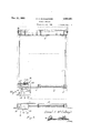
- Fig. 3 is a view of the curtain means for a right hand window of an automobile.
- Fig. 4 is a top plan View of the curtain operating means shown in Fig. 3.
- Fig. 5 is a section 'online 5-5 of Fig. 3.
- Fig. 6 is a sectionon line 6-6 of Fig. 3.
- the letter A indicates the front part of an automobile body and the letter B indicates thewindshield pane thereof. 7
- brackets 1 In carryingout my invention, I fasten brackets 1 to the inner face of the front part of the body and these brackets form bearings for the trunnions 2 of a roller on which is wound a curtain 3.
- Cords 4 are attached to the lower edge of the curtain in any suitable manner at the sides there-' of and these cords pass downwardly and are fastened to the drums 5 attached to a rod 6 at the ends thereof, this rod being rotatably supported in the brackets 7 attached to the inner face of the front part of the body below the transparent member 13.
- This rod passes through a casing 8 fastened to the body of the automobile by a bracket 9 and a spring 10 is located in the casing and has one end attached thereto and its other end attached to one of the drums 5, the spring tending to rotate the'drums and the rod 6 in a direction to wind up the cords 4 so as to pull down the curtain over the transparent member of the windshield as shown in Fig. 2.
- a beveled hook 11 attached to each side portion of the curtain adjacent the bottom thereof will engage a downwardly curved hookv 12 located under the transparent. member B, so that these two pairs of hooks will hold the curtain. in lowered position as'shownin Fig. 2.
- One of the drums 5 is formedwith a ratchet 13 which is engaged by adog 14 having a weight 15 attached to its lower end, this dog normally holding the rod 6 and the drums 5 against actuationby the spring 10 so that thecurtain will remain in rolled up positionat the top of the windshield.
- a small casing 16 encloses the ratchet carrying drum and the dog and the top of the casing has an opening 17 therein for passage of the cord 4, and alsinall shaft 18' is journalled in the casing and hasone end extending therefrom and formed with acrank handle 19.
- This shaft within the casing supports a double arm lever 20 the upper arm of which is normallyheld against the upper end of the dog by a small spring 21" on the shaft 18 and, by turning the shaft through means of the handle 19, the lower arm of the lever can be movedagai'nst the lower end ofthe dog so as to release the ratchet from the dog to'permit the curtain to be lowered or partly lowered. In the latter position, the curtain acts as a sun shade.
- v Figs. 3,4, 5 and 6 showthe invention applied to one of the windows of an automobile, and in this case, the cords 4' are attached to the drums 5' carried by the rod or shaft 6' located in the lower part of the window receivin opening of the automobile, with the spring 10' adapted to rotate the shaft drums in a direction to wind the cords on the drums to pull the curtain 3 over the transparent member of the window.
- One of the drums carries the ratchet 13 but the teeth of the ratchet are formed on a flange which extends from one end of the drum, as shown, and'said teeth are engaged by a dog 22 formed on a rod 23, the lower end of which has attached thereto a weight 2 and the upper end of the rod is beveled as shown at 25.
- a short shaft 26 is pivoted which is rotatably arranged in a bearing part formed in the bracket 27 located on a window receiving opening, and a weight 28 has an arm 29 thereon whieh is connected to the other end of the short shaft 25.
- the bearings for the shaft 6 and the bracket 27 are attached to an elongated bracket 30 which is suitably supported on a wall of the window re-. DCv ng. Opening and this bracket 30 carries a bracket 31 having a horizontal part 'on which is slidably arranged the plate 32 having the slots 33 therein for receiving the pins 34 carried by said horizontal part and springs .32 encircling the pins or bolts 34 and act to frictionally press the plate 32 on said horizontal part of the bracket 31.
- This plate 32 is provided with a V shape'd recess 35 through which passes the beveled end of the. rod 23.
- a handle 36 is attached to the plate 32 and extends through a slot in the inner wall of the window receiving opening, so that it can be manipulated by an occupant of the automobile.
- the shaft f6" and its associated parts are located in the lower part of the window receiving opening with the parts spaced suificient from the inner and outer walls of said opening to permit swinging movement of the weight 28 and theseweights 24 and 28 and their associated parts area'r 'fariged in the forward part of the window receiving opening.
- the plate 32 cccupies the dotted line position shown in Fig. 4
- the weight 28 would be caused to swing to release the tooth 22 from the ratchet l3 and thus the curtain would be lowered.
- a safety device for preventing fragments of a' broken trai'isparent member from injuring occupants of a vehicle comprising a curtain, a roller on which the curtain is wound, a shaft, means for connecting the shaft with the, cure. tain whereby rotary movement of the shaft will unwind the, roller, a spring for rotating the shaft, ratchet means, including a dog, for holding the shaft against movement by the spring, and a weight conn cted with the dog for movingthe dog to releasing position when a collision occurs the vehicle is upset.
- a safety device for preventing fragments of said transparent member, if the'same should break, from injuring occupants of the vehicle, said device comprising a curtain, a roller on which the curtain is wound, a shaft supported for rotary movement, a drum on the shaft, a flexiblez member having one end connected, with the drum and its other end with the curtain, a ratchet on the drum, a, spring for rotating the shaft to wind the fiexiblemember on the drum, a dog engaging the ratchet for preventing rotation of" the shaft by the spring and aweight connected with the dog, i
- a safety device for vehicles comprising a curtain, a roller upon whichithe curtain is wound, means for supporting theroller adjacent an. edge of the transparent member of the vehiclaa shaft rotatably supported adjacent an opposite edge of the, transparent member, drums on the shaft, flexible members connectedwith the drums and the curtain, a spring for rotating the shaft. to.
- drums drums, a pivoted dog engagingv the teeth, and a weight connected with the dog for inoving the dog to releasing position from the ,shockof acollision or the vehicle upsetting.
- a safety device for vehicles comprising a;
- a safety device for preventing the breaking of a transparent member of a vehicle from injuring occupants of the vehicle comprising a curtain, a roller on which the curtain is wound,
- a safety device for preventing the breaking of a transparent member of a vehicle from injuring occupants of a vehicle comprising a curtain, a roller on which the curtain is wound, means for supporting the roller adjacent one edge of the transparent member, a shaft rotatably supported adjacent an opposite edge thereof, a spring for rotating'the shaft, drums carried by the shaft, flexible members connecting the drums with the curtain, a ratchet connected with one drum, a dog engaging the ratchet, a weight on the dog for moving the dog to releasing position when a collision occurs, a shaft rotatably supported and to one end of which the dog is pivoted, the last-mentioned shaft paralleling the firstmentioned shaft, a second weight connected with the second-mentioned shaft and movable in a plane at right angles to the plane of movement of the first weight, and manually operated means for moving the dog back into engagement with the ratchet after the dog has been released from the ratchet.
Landscapes
- Engineering & Computer Science (AREA)
- Mechanical Engineering (AREA)
- Curtains And Furnishings For Windows Or Doors (AREA)
- Operating, Guiding And Securing Of Roll- Type Closing Members (AREA)
Description
.1933- s. A; M cuLLouGH SAFETY CURTAIN Filed July 12, 1952 3 Sheets-Sheet l famue r4 1 4 [zJ/oajz Nov. 21, 1933. s, MECULLOUGH 1,936,251
SAFETY CURTAIN Filed July 12, 1932 3 Sheets-Sheet 2 naw/,4. 4/ GJ/ouy By J flllomey Nov. 21, 1933. s A, MCCULLOUGH 1,936,251
SAFETY CURTAIN Filed July 12, 1932 3 Sheets-Sheet 3 a H Inventor fmue/ 4. M? (u/a z,
flwpwgim.
Patented Nov. 21 I933 UNITE. rATfE's PATENT mes 6 Claims. (01. 296-44) This invention relates to a safety, curtain for motor vehicles, the general object of the invention being to provide a curtain for the windshield and windows of an automobile with means for automatically moving thecurtain over the transparent member of the windshield or window if a collision should occur between the auto-v mobile'and another automobile or object or if the automobile should turnover.
This invention also consists in certain other features of construction and in the combination and arrangement of the several parts to be hereinafter fully described, illustrated in the accompanying drawings and specifically pointed out in the appended claims.
In describing the invention in detail, reference will be had to the accompanying drawings wherein like characters denote like or corresponding parts throughout the several views, and in which:--- 7 Figure 1 is a, fragmentary 'view looking towards the inner face of a windshield and its frame showing the invention in use, parts being shown in section,
Fig. 2 is a section on line 2-2 of Fig.1.
Fig. 3 is a view of the curtain means for a right hand window of an automobile.
Fig. 4 is a top plan View of the curtain operating means shown in Fig. 3.
Fig. 5 is a section 'online 5-5 of Fig. 3.
Fig. 6 is a sectionon line 6-6 of Fig. 3.
Referring first to Figs. 1 and '2, the letter A indicates the front part of an automobile body and the letter B indicates thewindshield pane thereof. 7
In carryingout my invention, I fasten brackets 1 to the inner face of the front part of the body and these brackets form bearings for the trunnions 2 of a roller on which is wound a curtain 3. Cords 4 are attached to the lower edge of the curtain in any suitable manner at the sides there-' of and these cords pass downwardly and are fastened to the drums 5 attached to a rod 6 at the ends thereof, this rod being rotatably supported in the brackets 7 attached to the inner face of the front part of the body below the transparent member 13. This rod passes through a casing 8 fastened to the body of the automobile by a bracket 9 and a spring 10 is located in the casing and has one end attached thereto and its other end attached to one of the drums 5, the spring tending to rotate the'drums and the rod 6 in a direction to wind up the cords 4 so as to pull down the curtain over the transparent member of the windshield as shown in Fig. 2.
beinginjured by when the curtain is so pulled down, a beveled hook 11 attached to each side portion of the curtain adjacent the bottom thereof will engage a downwardly curved hookv 12 located under the transparent. member B, so that these two pairs of hooks will hold the curtain. in lowered position as'shownin Fig. 2. One of the drums 5 is formedwith a ratchet 13 which is engaged by adog 14 having a weight 15 attached to its lower end, this dog normally holding the rod 6 and the drums 5 against actuationby the spring 10 so that thecurtain will remain in rolled up positionat the top of the windshield. However, if a collision occurs, the shock will throw the weight 15 forwardly so that the dog 14 is released from the ratchet which permits the spring '10 to rotate the rod and'the drums so that the cords will be'wound upon the drum and the curtain will be pulled downwardly until the hooks 11 engage the hooks 12 and thus the curtain will beheld in 'stretched position in rear of the transparentjportion of the windshieldfso that if the windshield pane should be broken the flying glass will not'harm the occupants of the automobile. 1
A small casing 16 encloses the ratchet carrying drum and the dog and the top of the casing has an opening 17 therein for passage of the cord 4, and alsinall shaft 18' is journalled in the casing and hasone end extending therefrom and formed with acrank handle 19. This shaft within the casing supports a double arm lever 20 the upper arm of which is normallyheld against the upper end of the dog by a small spring 21" on the shaft 18 and, by turning the shaft through means of the handle 19, the lower arm of the lever can be movedagai'nst the lower end ofthe dog so as to release the ratchet from the dog to'permit the curtain to be lowered or partly lowered. In the latter position, the curtain acts as a sun shade. Thus it will be seen that when a headon collisionoccurs or the car strikes an object, the resultant shock will release the dog from the ratchet and the curtain will be pulled downwardly to cover the transparent member and thus prevent the occupants of the automobile from' the'breaking of the transparent member.
It will also be seen that by moving the dog to releasing position by means of the shaft 18 the v curtain may be partly lowered so that the same can be used as-a sunshade. v Figs. 3,4, 5 and 6 showthe invention applied to one of the windows of an automobile, and in this case, the cords 4' are attached to the drums 5' carried by the rod or shaft 6' located in the lower part of the window receivin opening of the automobile, with the spring 10' adapted to rotate the shaft drums in a direction to wind the cords on the drums to pull the curtain 3 over the transparent member of the window. One of the drums carries the ratchet 13 but the teeth of the ratchet are formed on a flange which extends from one end of the drum, as shown, and'said teeth are engaged by a dog 22 formed on a rod 23, the lower end of which has attached thereto a weight 2 and the upper end of the rod is beveled as shown at 25.
Intermediate the ends of the rod 23 a short shaft 26 is pivoted which is rotatably arranged in a bearing part formed in the bracket 27 located on a window receiving opening, and a weight 28 has an arm 29 thereon whieh is connected to the other end of the short shaft 25. The bearings for the shaft 6 and the bracket 27 are attached to an elongated bracket 30 which is suitably supported on a wall of the window re-. ceiv ng. Opening and this bracket 30 carries a bracket 31 having a horizontal part 'on which is slidably arranged the plate 32 having the slots 33 therein for receiving the pins 34 carried by said horizontal part and springs .32 encircling the pins or bolts 34 and act to frictionally press the plate 32 on said horizontal part of the bracket 31. This plate 32 is provided with a V shape'd recess 35 through which passes the beveled end of the. rod 23.
A handle 36 is attached to the plate 32 and extends through a slot in the inner wall of the window receiving opening, so that it can be manipulated by an occupant of the automobile.
The shaft f6" and its associated parts are located in the lower part of the window receiving opening with the parts spaced suificient from the inner and outer walls of said opening to permit swinging movement of the weight 28 and theseweights 24 and 28 and their associated parts area'r 'fariged in the forward part of the window receiving opening. Normally the plate 32 cccupies the dotted line position shown in Fig. 4
so that the upper end of the rod 23 will be permittedto move rearwardly when the weight 24 moves forwardly if the vehicle should strike an object'infront of it. Thus if a head-on collision occurs the weight 24 will move forwardly and v the upper end of the rod 23 will move rearwardly When said rod 23 rocks on the pivot 23' which connects it with the shaft 26. This movement of the rod 23. moves the dog 22 out of engagement with the ratchet teeth 13 ofthe forward drum 5 and thus the spring 10, will rotate the shaft 6' and the'dru ns and thus the curtain will be lowered and prevent particles of glass injuring. the occupants of the vehicle. 7 I v If the vehicle should upset on its right side I the weight, 28 wouldmove toward the right and thus rotate, the shaft 26 which would swing the tooth carrying Dart of the rod 23 outwardly from the toothed flange of the drum 5 so that-the tooth 22 of the rod 23 wouldv be released from .i the teeth of the ratchet and thus the shaft 6' would berotated by the spring 10' and'the curtain 3 lowered. If the vehicle should upset toward, its left side the weight 28 would swing in the opposite direction and the tooth 22 of the rod 23 would swing into the circular space formed by the flange which carries theteeth 13 so that the shaft 6' would be released and the spring 19 would lower the curtain. If the vehicle was struck on either side by another vehicle,
the weight 28 would be caused to swing to release the tooth 22 from the ratchet l3 and thus the curtain would be lowered.
When it is desired to return the dog 22 into engagement with the teeth of the ratchet 13' the plate 32 is moved forward by its handle 36 and the V-shaped notch 35 will position the rod 23 so that the tooth 22 will engage the teeth of the ratchet 13. rearwardly to the dotted line position shown in It is thought from the foregoing description that the advantages and novel features of the invention will be readily apparent.
It is to be understood that changes may be made in the censtruction and in the combination and arrangement of the several parts, provided that such chan es fall within the scope of the appended claims.
Having thus described invention, what I claini as new is:
l. A safety device for preventing fragments of a' broken trai'isparent member from injuring occupants of a vehicle comprising a curtain, a roller on which the curtain is wound, a shaft, means for connecting the shaft with the, cure. tain whereby rotary movement of the shaft will unwind the, roller, a spring for rotating the shaft, ratchet means, including a dog, for holding the shaft against movement by the spring, and a weight conn cted with the dog for movingthe dog to releasing position when a collision occurs the vehicle is upset.
2. In a vehicle DI'OVided With a transparent member, a safety device for preventing fragments of said transparent member, if the'same should break, from injuring occupants of the vehicle, said device comprising a curtain, a roller on which the curtain is wound, a shaft supported for rotary movement, a drum on the shaft, a flexiblez member having one end connected, with the drum and its other end with the curtain, a ratchet on the drum, a, spring for rotating the shaft to wind the fiexiblemember on the drum, a dog engaging the ratchet for preventing rotation of" the shaft by the spring and aweight connected with the dog, i
3. A safety device for vehicles comprising a curtain, a roller upon whichithe curtain is wound, means for supporting theroller adjacent an. edge of the transparent member of the vehiclaa shaft rotatably supported adjacent an opposite edge of the, transparent member, drums on the shaft, flexible members connectedwith the drums and the curtain, a spring for rotating the shaft. to.
wind the flexible members upon the drums to move the. curtain over the, inner face of the transparent member, ratchet teeth on one of the,
drums, a pivoted dog engagingv the teeth, and a weight connected with the dog for inoving the dog to releasing position from the ,shockof acollision or the vehicle upsetting.
i. A safety device for vehicles comprising a;
curtain, a roller upon which the means for support of the transparent curtain is wound, g the roller adjacent. an edge member .of thevehicle, a shaft rotatably supported adjacent an. opposite edge of the transparent member, drums on the shaft,
transparent member, the drums, a pivoted ratchet teeth on d rect dog, engaging the teeth, a
weight connected with the dog for rnovingthef Then the plate 32 is moved collision or the vehicle upsetting, and manually operated means for moving the dog to releasing position.
5. A safety device for preventing the breaking of a transparent member of a vehicle from injuring occupants of the vehicle comprising a curtain, a roller on which the curtain is wound,
means for supporting the roller adjacent one edge of the transparent member, a, shaft rotatably supported adjacent an opposite edge thereof, a spring for rotating the shaft, drums carried by the shaft, flexible members connecting the drums with the curtain, a ratchet connected with one drum, a dog engaging the ratchet, a weight on the dog for moving the dog to releasing position when a collision occurs, a shaft rotatably supported and to one end of which the dog is pivoted, the last-mentioned shaft paralleling the first-mentioned shaft, and asecond weight connected with the second-mentioned shaft and movable in a plane at right angles to the plane of movement of the first weight.
6. A safety device for preventing the breaking of a transparent member of a vehicle from injuring occupants of a vehicle comprising a curtain, a roller on which the curtain is wound, means for supporting the roller adjacent one edge of the transparent member, a shaft rotatably supported adjacent an opposite edge thereof, a spring for rotating'the shaft, drums carried by the shaft, flexible members connecting the drums with the curtain, a ratchet connected with one drum, a dog engaging the ratchet, a weight on the dog for moving the dog to releasing position when a collision occurs, a shaft rotatably supported and to one end of which the dog is pivoted, the last-mentioned shaft paralleling the firstmentioned shaft, a second weight connected with the second-mentioned shaft and movable in a plane at right angles to the plane of movement of the first weight, and manually operated means for moving the dog back into engagement with the ratchet after the dog has been released from the ratchet.
SAMUEL A. MCCULLOUGH.
Priority Applications (1)
| Application Number | Priority Date | Filing Date | Title |
|---|---|---|---|
| US622144A US1936251A (en) | 1932-07-12 | 1932-07-12 | Safety curtain |
Applications Claiming Priority (1)
| Application Number | Priority Date | Filing Date | Title |
|---|---|---|---|
| US622144A US1936251A (en) | 1932-07-12 | 1932-07-12 | Safety curtain |
Publications (1)
| Publication Number | Publication Date |
|---|---|
| US1936251A true US1936251A (en) | 1933-11-21 |
Family
ID=24493098
Family Applications (1)
| Application Number | Title | Priority Date | Filing Date |
|---|---|---|---|
| US622144A Expired - Lifetime US1936251A (en) | 1932-07-12 | 1932-07-12 | Safety curtain |
Country Status (1)
| Country | Link |
|---|---|
| US (1) | US1936251A (en) |
Cited By (21)
| Publication number | Priority date | Publication date | Assignee | Title |
|---|---|---|---|---|
| US2757040A (en) * | 1953-06-12 | 1956-07-31 | Roger T Mclelland | Head protecting shock absorber for vehicle windshields |
| US2822187A (en) * | 1955-09-01 | 1958-02-04 | John D Bibbs | Safety crash pad for vehicles |
| US2942913A (en) * | 1959-06-16 | 1960-06-28 | Basil B Felts | Safety curtain for automotive vehicles |
| US3133746A (en) * | 1961-11-29 | 1964-05-19 | Joseph R Zazzara | Vehicle occupant guard |
| JPS4849726U (en) * | 1971-10-13 | 1973-06-29 | ||
| US3774936A (en) * | 1970-10-16 | 1973-11-27 | Gen Motors Corp | Occupant restraint system |
| JPS5344813U (en) * | 1976-09-20 | 1978-04-17 | ||
| DE2739741A1 (en) | 1977-09-03 | 1979-03-15 | Daimler Benz Ag | A REAR DOOR LOCKING A LOAD AREA OF A CAR |
| DE2759777C2 (en) * | 1977-09-03 | 1986-06-26 | Daimler-Benz Ag, 7000 Stuttgart | Protective device designed as a roller blind |
| US5299830A (en) * | 1991-03-26 | 1994-04-05 | European Components Corporation | Safety belt pre-tension assembly |
| US5551726A (en) * | 1993-10-25 | 1996-09-03 | Baumeister +Ostler Gmbh & Co. | Safety net system for a motor vehicle to separate a cargo compartment from a passenger compartment |
| US5599042A (en) * | 1995-12-14 | 1997-02-04 | Chorng Rong Shyr | Safety air curtain for vehicles |
| US5707075A (en) * | 1991-11-15 | 1998-01-13 | Mst Automotive Gmbh | Protecting apparatus |
| US5971433A (en) * | 1996-10-23 | 1999-10-26 | Baumeister & Ostler Gmbh & Co. | Safety net device |
| US6135497A (en) * | 1998-06-29 | 2000-10-24 | Trw Vehicle Safety Systems Inc. | Vehicle occupant protection apparatus |
| US20050051283A1 (en) * | 2001-12-21 | 2005-03-10 | David Chatellard | Motor-driven shutter or sun-shading device |
| US20070199771A1 (en) * | 2005-10-21 | 2007-08-30 | Inventio Ag | Elevator Door System |
| US20090115170A1 (en) * | 2007-11-07 | 2009-05-07 | Erik Hjerpe | Safety Device for the Protection of Vehicle Occupants |
| GB2511393A (en) * | 2013-12-16 | 2014-09-03 | Daimler Ag | Passenger restraint system for a vehicle |
| US10294718B2 (en) * | 2005-12-12 | 2019-05-21 | Centor Design Pty Ltd | Pull across roll up screen assembly |
| USD865223S1 (en) | 2017-11-03 | 2019-10-29 | Centor Design Pty Ltd | Screen mounting tube |
-
1932
- 1932-07-12 US US622144A patent/US1936251A/en not_active Expired - Lifetime
Cited By (23)
| Publication number | Priority date | Publication date | Assignee | Title |
|---|---|---|---|---|
| US2757040A (en) * | 1953-06-12 | 1956-07-31 | Roger T Mclelland | Head protecting shock absorber for vehicle windshields |
| US2822187A (en) * | 1955-09-01 | 1958-02-04 | John D Bibbs | Safety crash pad for vehicles |
| US2942913A (en) * | 1959-06-16 | 1960-06-28 | Basil B Felts | Safety curtain for automotive vehicles |
| US3133746A (en) * | 1961-11-29 | 1964-05-19 | Joseph R Zazzara | Vehicle occupant guard |
| US3774936A (en) * | 1970-10-16 | 1973-11-27 | Gen Motors Corp | Occupant restraint system |
| JPS4849726U (en) * | 1971-10-13 | 1973-06-29 | ||
| JPS5344813U (en) * | 1976-09-20 | 1978-04-17 | ||
| DE2739741A1 (en) | 1977-09-03 | 1979-03-15 | Daimler Benz Ag | A REAR DOOR LOCKING A LOAD AREA OF A CAR |
| DE2759777C2 (en) * | 1977-09-03 | 1986-06-26 | Daimler-Benz Ag, 7000 Stuttgart | Protective device designed as a roller blind |
| US5299830A (en) * | 1991-03-26 | 1994-04-05 | European Components Corporation | Safety belt pre-tension assembly |
| US5707075A (en) * | 1991-11-15 | 1998-01-13 | Mst Automotive Gmbh | Protecting apparatus |
| US5551726A (en) * | 1993-10-25 | 1996-09-03 | Baumeister +Ostler Gmbh & Co. | Safety net system for a motor vehicle to separate a cargo compartment from a passenger compartment |
| US5599042A (en) * | 1995-12-14 | 1997-02-04 | Chorng Rong Shyr | Safety air curtain for vehicles |
| US5971433A (en) * | 1996-10-23 | 1999-10-26 | Baumeister & Ostler Gmbh & Co. | Safety net device |
| US6135497A (en) * | 1998-06-29 | 2000-10-24 | Trw Vehicle Safety Systems Inc. | Vehicle occupant protection apparatus |
| US20050051283A1 (en) * | 2001-12-21 | 2005-03-10 | David Chatellard | Motor-driven shutter or sun-shading device |
| US20070199771A1 (en) * | 2005-10-21 | 2007-08-30 | Inventio Ag | Elevator Door System |
| US7617860B2 (en) * | 2005-10-21 | 2009-11-17 | Inventio Ag | Elevator door system |
| US10294718B2 (en) * | 2005-12-12 | 2019-05-21 | Centor Design Pty Ltd | Pull across roll up screen assembly |
| US20090115170A1 (en) * | 2007-11-07 | 2009-05-07 | Erik Hjerpe | Safety Device for the Protection of Vehicle Occupants |
| US7938439B2 (en) * | 2007-11-07 | 2011-05-10 | Autoliv Development Ab | Safety device for the protection of vehicle occupants |
| GB2511393A (en) * | 2013-12-16 | 2014-09-03 | Daimler Ag | Passenger restraint system for a vehicle |
| USD865223S1 (en) | 2017-11-03 | 2019-10-29 | Centor Design Pty Ltd | Screen mounting tube |
Similar Documents
| Publication | Publication Date | Title |
|---|---|---|
| US1936251A (en) | Safety curtain | |
| US3133746A (en) | Vehicle occupant guard | |
| US1745695A (en) | Antiglare device | |
| US2661221A (en) | Safety passenger holding device for automotive vehicles | |
| US1461478A (en) | Protective ventilating screen for vehicles | |
| US2120892A (en) | Telescope sun visor | |
| US1795184A (en) | Glare shade | |
| US2050141A (en) | Automatic automobile life preserver | |
| US2991119A (en) | Glare shield and sun reflector | |
| US1775486A (en) | Glare shield, draft regulator, and antirattler for automobiles | |
| US2791272A (en) | Anti-glare shade for automobile windshields | |
| US1557388A (en) | Antiglare device | |
| US2445473A (en) | Glare screen | |
| US2501250A (en) | Sunrays and reflected glare arresting device | |
| US2942913A (en) | Safety curtain for automotive vehicles | |
| GB1581897A (en) | Motor vehicle having an internal courtesy mirror | |
| US2458918A (en) | Sun visor | |
| US1548396A (en) | Windshield curtain | |
| US3244447A (en) | Automobile sun visors | |
| US1842991A (en) | Antiglare shield for automobiles | |
| US1837546A (en) | Antiglare shield | |
| US1272958A (en) | Automobile storm-awning. | |
| US1733371A (en) | Safety shield for automobile windshields | |
| US1764478A (en) | Nonglare shield | |
| US1766884A (en) | Glare protector |