EP0837381A2 - Elektrische Heizung - Google Patents
Elektrische Heizung Download PDFInfo
- Publication number
- EP0837381A2 EP0837381A2 EP19970117886 EP97117886A EP0837381A2 EP 0837381 A2 EP0837381 A2 EP 0837381A2 EP 19970117886 EP19970117886 EP 19970117886 EP 97117886 A EP97117886 A EP 97117886A EP 0837381 A2 EP0837381 A2 EP 0837381A2
- Authority
- EP
- European Patent Office
- Prior art keywords
- heating
- control
- controller
- variable
- linear
- Prior art date
- Legal status (The legal status is an assumption and is not a legal conclusion. Google has not performed a legal analysis and makes no representation as to the accuracy of the status listed.)
- Granted
Links
- 238000010438 heat treatment Methods 0.000 title claims abstract description 152
- 238000005485 electric heating Methods 0.000 claims abstract description 4
- 239000002826 coolant Substances 0.000 claims description 3
- 230000001105 regulatory effect Effects 0.000 abstract description 7
- 239000004065 semiconductor Substances 0.000 description 13
- 239000000498 cooling water Substances 0.000 description 7
- 238000001816 cooling Methods 0.000 description 5
- 238000010586 diagram Methods 0.000 description 4
- 230000000694 effects Effects 0.000 description 3
- 238000000034 method Methods 0.000 description 3
- RYGMFSIKBFXOCR-UHFFFAOYSA-N Copper Chemical compound [Cu] RYGMFSIKBFXOCR-UHFFFAOYSA-N 0.000 description 2
- 230000000052 comparative effect Effects 0.000 description 2
- 229910052802 copper Inorganic materials 0.000 description 2
- 239000010949 copper Substances 0.000 description 2
- 239000000446 fuel Substances 0.000 description 2
- 230000008569 process Effects 0.000 description 2
- 230000009467 reduction Effects 0.000 description 2
- 230000007704 transition Effects 0.000 description 2
- XLYOFNOQVPJJNP-UHFFFAOYSA-N water Substances O XLYOFNOQVPJJNP-UHFFFAOYSA-N 0.000 description 2
- 238000002485 combustion reaction Methods 0.000 description 1
- 230000001276 controlling effect Effects 0.000 description 1
- 238000011161 development Methods 0.000 description 1
- 230000018109 developmental process Effects 0.000 description 1
- 238000010292 electrical insulation Methods 0.000 description 1
- 238000009413 insulation Methods 0.000 description 1
- 230000007257 malfunction Effects 0.000 description 1
- 238000012544 monitoring process Methods 0.000 description 1
- 230000004044 response Effects 0.000 description 1
Images

Classifications
-
- B—PERFORMING OPERATIONS; TRANSPORTING
- B60—VEHICLES IN GENERAL
- B60H—ARRANGEMENTS OF HEATING, COOLING, VENTILATING OR OTHER AIR-TREATING DEVICES SPECIALLY ADAPTED FOR PASSENGER OR GOODS SPACES OF VEHICLES
- B60H1/00—Heating, cooling or ventilating [HVAC] devices
- B60H1/22—Heating, cooling or ventilating [HVAC] devices the heat being derived otherwise than from the propulsion plant
- B60H1/2215—Heating, cooling or ventilating [HVAC] devices the heat being derived otherwise than from the propulsion plant the heat being derived from electric heaters
- B60H1/2218—Heating, cooling or ventilating [HVAC] devices the heat being derived otherwise than from the propulsion plant the heat being derived from electric heaters controlling the operation of electric heaters
-
- B—PERFORMING OPERATIONS; TRANSPORTING
- B60—VEHICLES IN GENERAL
- B60H—ARRANGEMENTS OF HEATING, COOLING, VENTILATING OR OTHER AIR-TREATING DEVICES SPECIALLY ADAPTED FOR PASSENGER OR GOODS SPACES OF VEHICLES
- B60H1/00—Heating, cooling or ventilating [HVAC] devices
- B60H1/22—Heating, cooling or ventilating [HVAC] devices the heat being derived otherwise than from the propulsion plant
- B60H1/2215—Heating, cooling or ventilating [HVAC] devices the heat being derived otherwise than from the propulsion plant the heat being derived from electric heaters
- B60H1/2221—Heating, cooling or ventilating [HVAC] devices the heat being derived otherwise than from the propulsion plant the heat being derived from electric heaters arrangements of electric heaters for heating an intermediate liquid
-
- G—PHYSICS
- G05—CONTROLLING; REGULATING
- G05B—CONTROL OR REGULATING SYSTEMS IN GENERAL; FUNCTIONAL ELEMENTS OF SUCH SYSTEMS; MONITORING OR TESTING ARRANGEMENTS FOR SUCH SYSTEMS OR ELEMENTS
- G05B11/00—Automatic controllers
- G05B11/01—Automatic controllers electric
- G05B11/06—Automatic controllers electric in which the output signal represents a continuous function of the deviation from the desired value, i.e. continuous controllers
-
- G—PHYSICS
- G05—CONTROLLING; REGULATING
- G05B—CONTROL OR REGULATING SYSTEMS IN GENERAL; FUNCTIONAL ELEMENTS OF SUCH SYSTEMS; MONITORING OR TESTING ARRANGEMENTS FOR SUCH SYSTEMS OR ELEMENTS
- G05B6/00—Internal feedback arrangements for obtaining particular characteristics, e.g. proportional, integral or differential
- G05B6/02—Internal feedback arrangements for obtaining particular characteristics, e.g. proportional, integral or differential electric
Definitions
- the invention relates to an electric heater according to the preamble of claim 1.
- Electric heaters or heating systems are for example in Motor vehicles needed for different applications to Example of temperature control (heating) of the room air Preheating the cooling water in water-cooled engines to Preheating the spark plugs for self-igniting Internal combustion engines, for heating fuel (diesel) etc.
- Such heating systems usually consist of a heater with at least one heating level, each at least one (For example, as a heating resistor) heating element have to generate a certain heating power and from a control unit for monitoring the timing and to specify the heating output; Heating and control unit are designed as separate modules (functional units) and at various points within the motor vehicle arranged.
- the control unit can be controlled by means of a various controllers can be realized when they occur a control deviation or control difference a different one Effect control behavior; for example Proportional controller, integral controller, differential controller, Linear controllers or switchable step controllers commonly used. To the To reduce the load on the control device, this can several controllers, which are usually built as switchable step controllers are formed and for example activated and deactivated by switching processes. The problem here is (especially with step controllers) Delimitation of the areas of activity of the various controllers, i.e.
- the invention has for its object a simple electric heating with low power dissipation.
- this is at least two Heater with heating levels as a controlled system
- Control loop formed together with the control device of the control loop is integrated into a common housing.
- the heating output of the heating i.e. the heating level (s) are regulated as a controlled variable; however often instead of the actual controlled variable heating output preferably a variable determining the heating power as actual controlled variable used, i.e. it will either be the Current through the heating stage / s or the heating elements (the Heating current) or the voltage at the heating level (s) Heating elements (the heating voltage) regulated.
- this (for example voltage-controlled) control loop Setpoint of the quantity determining the heating output (for example the heating voltage), this setpoint with the actual value of the quantity determining the heating output (e.g. heating voltage) compared, and deviations between setpoint and actual value (the control deviation or Control difference) automatically by feedback within the Control loop minimized.
- the actual value of the quantity determining the heating output e.g. heating voltage
- At least one is preferably used as the control device Linear regulator used; such linear controllers (continuous Controllers) have no discontinuities in their control process (in In contrast to a switched controller).
- linear controllers continuous Controllers
- a switched controller In contrast to a switched controller
- the setpoint of the heating power control variable or the The heating power determining size can be determined either by means of a Reference variable can be varied, for example by means of a external input signal supplied to the control loop or by means of a (for example in the control loop generated) direct control signal for the heating power or for the quantity that determines the heat output.
- control variable heating power or the heating power determining size generating heating elements of the heating level / s of Heating are preferably used as heating resistors educated.
- the semiconductor components are preferably the Control device, in particular its power transistors, for Reduction of thermal resistance on a common Carrier body with high thermal conductivity (for example on a copper plate) applied.
- the heating system can be used to heat a circuit bound media, i.e. in a heat cycle and / or in media located in a cooling circuit of the motor vehicle (e.g. water, air, oil, etc.) can be used (for example for the cooling water heating of the Motor vehicle); alternatively for heating from not on a cycle - bound media (for example for the Interior heating of the motor vehicle).
- a circuit bound media i.e. in a heat cycle and / or in media located in a cooling circuit of the motor vehicle
- a cooling circuit of the motor vehicle e.g. water, air, oil, etc.
- the heating power of the heating elements of the heating system should both set dynamically and statically with minimal errors or be specified.
- this is done within the voltage controlled Control circuit RK from control device 1, control system 2 (heating from at least one heating level with at least one Heating element) and setpoint adjuster 31 the heating power as Controlled variable RG using the manipulated variable SG voltage drop at the Heating 2 (heating voltage) regulated.
- control signal SS activatable / deactivatable setpoint adjuster 31 for example by means of an external control signal GS
- This control difference RD or Control deviation is the control device 1 (for example at least one linear controller) and from this the Control variable SG heating voltage generated.
- the controlled system 2 heating
- the heating 2 the heating levels or the heating elements of the Heating levels
- a certain heating output as (actual value of) Control variable RG generated.
- the heating power as a controlled variable RG on the one hand at the output of the control circuit RK as the output signal AS spent (the cooling water circuit of the motor vehicle fed) and thereby heating the cooling water made and on the other in the feedback loop of the Control circuit RK fed to comparator 32 as the actual value.
- RG is one of the two Used to determine the heat output, i.e. either the Current through the heating 2 or the heating levels (heating current) or the voltage drop across the heating 2 or heating levels (Heating voltage); for example, the heating voltage is considered Controlled variable RG is used, in this case the controlled variable RG identical to the manipulated variable SG.
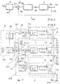
- the heating 2 is implemented by means of three heating stages 21, 22, 23 connected in parallel and each having a heating element; the heating elements of the heating stages 21, 22, 23 are designed, for example, as heating resistors and are connected between the supply voltage V S (for example + 12 V) and the reference potential GND.
- the control device 1 is implemented by means of three parallel-connected linear controllers 11, 12, 13, each heating stage 21, 22, 23 or each heating element being connected to the output of a linear controller 11, 12, 13 and thus with a specific manipulated variable SG (SG1, SG2 , SG3) is applied as a voltage drop at heating stage 21, 22, 23 or the heating element (heating voltage).
- the heating power or the heating voltage as a feedback controlled variable RG (RG1, RG2, RG3) is fed to the comparator 32 from three comparison elements 321, 322, 323, with each linear controller 11, 12, 13 being assigned a comparison element 321, 322, 323; the comparison elements 321, 322, 323 are designed such that each linear controller 11, 12, 13 is acted upon with a certain control difference RD1, RD2, RD3 in such a way that each linear controller 11, 12, 13 has a different control range (only one becomes the linear controller 11, 12, 13 operated in linear mode) and thereby the heating output is continuously controlled without dead areas, overlaps or discontinuities (hysteresis, jump points) in the course of the control.
- the linear controller 11 for the lowest control range is the Command variable FG generated by the setpoint adjuster 31 fed. With the subsequent, next higher control range an additional heating output should only be brought about if the heating power of the underlying control range can no longer be effected can.
- a corresponding one for the next higher controller Generating a benchmark is the difference from that of the Setpoint adjuster 31 predetermined reference variable FG and the in Dependence on this reference variable FG from the first controller 11 generated manipulated variable SG1. Once the first regulator has reached the upper limit of its control range between the command variable FG and the manipulated variable SG1 Difference RD1 no longer from the first controller 11 can be compensated. This difference RD1 that in the Comparative element V1 is determined as the reference variable Controller 12 supplied to the subsequent control range.
- controller 12 can reach its upper limit Control range a further increase in heating output no longer cause.
- a command variable RD1 has been generated is also used for the controller 13 of the next following control area determined.
- the difference supplied to the controller RD1 and that generated in response to this variable by controller 12 Actuating variable SG2 in comparison element V2 is the difference RD2 determined.
- This difference RD2 is the reference variable Regulator 13 fed. In this way, the controller 13 only then an additional heating power if this over the Setpoint adjuster 31 is requested by the controllers 11 and 12 with the respectively connected heating resistors 21 and 22, but can no longer be effected.
- the entire heating area can be designed according to this principle divide into any number of sub-control ranges, and so on for example the average controller power loss low hold.
- the target heating output specified from outside becomes this initially fed to the lowest of the control ranges.
- For one seamless, i.e. continuous transition of the control ranges is the controller for the next higher control ranges only the difference from the next lowest controller supplied target size and the subsequently generated by this Control variable supplied.
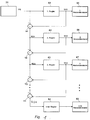
- FIG. 1 A simple circuit diagram to illustrate this principle is shown in Fig. 1.
- Fig. 1 are only the essential Elements of such a heating system for controlling seamless control ranges.
- Target heating power FG is fed to the first controller 61.
- the first controller generates a function of the reference variable FG 61 a manipulated variable SG1, that of the associated with this controller first heating stage 65 is fed.
- This difference RD1 is the second controller 62 supplied.
- the second controller generates in Dependence on the difference RD1 supplied to it Actuating variable SG2, which is the heating power of the second heating level 66 controls.
- the third controller 63 Difference from the difference fed to the second controller 62 RD1 and that of the second controller 62 depending on the Difference RD1 generated manipulated variable SG2 and the third Controller 63 fed as a reference variable.
- the third controller too 63 generates one depending on the difference RD2 Manipulated variable SG3 to the heating power of the third Control heating resistor 67. From the difference RD2 and the Actuating variable SG3 becomes a further difference in comparator V3 formed until finally for the last controller 64 with the connected heating stage 68 the difference RD4 in the comparator V4 is formed.
- the reference variable FG that determines the setpoint value is given in 3 by means of the setpoint adjuster 31, for example in Dependency of the degree of utilization of the generator of the Motor vehicle generated; for example, the leader FG and thus the setpoint specification for the heating output in Dependency of those still available from the generator Output power by means of an externally supplied Generator signal GS varies - for example, the Heating power regulated so that the generator shortly before its Maximum power is operated (for example at 95% of the maximum power).
- the control circuit RK is released or blocked (control activated or deactivated).
- the control circuit RK can thus also with high impedance without adjustment Heating resistors of heating levels 21, 22, 23 and with different resistance values of the heating resistors Heating levels 21, 22, 23 can be realized.
- the maximum value of the command variable FG is based on the sum of the Control limits of the individual linear controllers 11, 12, 13 and thus based on the maximum value of the controlled variable RG.
- the reference variable FG is set using the setpoint adjuster 31 for example depending on the externally supplied Control signal GS varies. Using a setpoint adjuster The control signal SS supplied to the control loop 1 enabled or blocked (the control is activated or deactivated).
- FIG. 7 shows the time profile of the control variables RG1, RG2, RG3 of the individual linear controllers 11, 12, 13 of the control device 1 and the time profile of the control variable RG (overall control profile) of the control device 1 with a continuous increase in the reference variable FG to at their maximum value FG max .
- the values FG 1 , FG 2 and FG 3 of the reference variable FG depend on the structure or type of the respective controller and result from the fact that the controller that is active up to that point can no longer regulate its specified setpoint (ie reaches its controller limit).
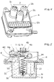
- the control circuit RK consisting of (the invisible) control device 1 and the heater 2 (heating stages 21, 22, 23) is integrated in a housing 4.
- the ribs 53 serve to enlarge the surface at the point where the power loss of the power semiconductor components of the control device 1 arises and thus to increase the heating effect.
- the connection of the control circuit RK for the reference potential GND can be made via the housing 4, so that in addition to the signal lines, only the connection for the supply voltage V S has to be provided.
- the housing 4 of the heating system is defined Preheating the (cooling) medium 52 of the cooling circuit 5 one (For example, water-cooled) motor vehicle in the Receiving device 51 of the cooling circuit 5 arranged that the Heating 2 with heating levels 21, 22, 23 or heating elements ins Cooling medium 52 (for example water) immersed and thus from Cooling medium (52) flows around.
- the housing 4 has a Connection part 45 for signal lines, by means of which Heating system external signals can be supplied (for example the control signal SS or the generator signal GS) or output signals provided by the heating system will.
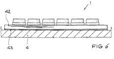
- the semiconductor components of the control device 1 for example the linear regulator 11, 12, 13), in particular the Power semiconductor devices (e.g.
- Power transistors are good on a common thermally conductive support body 42 (for example a Copper plate) applied above the ribs 53 is arranged; the connection between (the Semiconductor components) of the control device 1 and (the Heating elements 21, 22, 23) of heating level 2 is carried out by means of at least one contact connection 24.
- a common thermally conductive support body 42 for example a Copper plate
- the connection between (the Semiconductor components) of the control device 1 and (the Heating elements 21, 22, 23) of heating level 2 is carried out by means of at least one contact connection 24.
- this common carrier body 42 is arranged on the housing 4 (above the ribs 53); an insulation layer 43 for electrical insulation of the support body 42 and the housing 4 is provided between the support body 42 and the housing 4.
- the other linear regulators 11, 12, 13 are either deactivated (no power loss) or operated in saturation mode are (combined with a low power loss), the effective thermal resistance for the respective linear controller 11, 12, 13 in linear operation corresponding to the number of linear controllers 11, 12, 13 of the control device 1 and thus the temperature load of the semiconductor components (in particular the power transistors) of the control device 1 reduced.
- the heating system is neither on motor vehicles nor on the described embodiment is limited, for example the heating elements of the heating level can also be used with PTC elements will be realized. Instead of cooling water heating the heating system can also be used in other applications Motor vehicle (either circulatory or non-circulatory) are used, for example for the Air heating (interior heating) or for preheating (Diesel) fuel.
Landscapes
- Physics & Mathematics (AREA)
- Engineering & Computer Science (AREA)
- General Physics & Mathematics (AREA)
- Automation & Control Theory (AREA)
- Thermal Sciences (AREA)
- Mechanical Engineering (AREA)
- Air-Conditioning For Vehicles (AREA)
- Control Of Resistance Heating (AREA)
- Feedback Control In General (AREA)
Abstract
Description
- ist das Heizsystem als kompakte funktionsfähige Einheit realisierbar,
- ist keine Abstimmung zwischen der Heizung und einer Kontrolleinheit erforderlich,
- besteht nur ein geringer Aufwand für externe Anschlüsse, die Heizelemente der Heizstufe/n müssen seitens des Anwenders nicht mehr angeschlossen werden;
- wird die Verlustleistung (der Halbleiterbauelemente) der Regeleinrichtung zum Heizen mitverwendet, wodurch man außerdem einen linearen Zusammenhang zwischen dem Heizstrom und der Heizleistung erhält.
- werden Schaltvorgänge vermieden und demzufolge auch die durch Schaltvorgänge bedingten Störungen der Regelung (Auftreten von Totbereichen Überlappungen, Hysteresen, undefinierten Zuständen etc.),
- werden EMV-Störungen weitgehend vermieden, so daß keine kostenintensiven Bauelemente zur Beseitigung der EMV-Problematik benötigt werden.
- Figur 1
- ein Prinzipschaltbild zur Veranschaulichung der Regelung der elektronischen Heizung,
- Figur 2
- ein Prinzipschaltbild des Regelkreises,
- Figur 3
- ein Ausführungsbeispiel des Regelkreises,
- Figur 4
- eine perspektivische Ansicht des Heizsystems,
- Figur 5
- eine Schnittzeichnung des in einen Kühlkreislauf (beispielsweise den Kühlwasserkreislauf) des Kraftfahrzeugs integrierten Heizsystems,
- Figur 6
- eine Anordnung der Halbleiterbauelemente der Regeleinrichtung, und
- Figur 7
- ein Diagramm zur Veranschaulichung des Regelverhaltens.
Claims (5)
- Elektrische Heizung mit wenigstens zwei elektrischen Heizwiderständen, deren Heizleistung von einer Regeleinrichtung einstellbar ist, dadurch gekennzeichnet, daß die Regeleinrichtung (1) eine der Anzahl der Heizwiderstände entsprechende Anzahl von Reglern (11, 12, 13) aufweist, denen jeweils einer der elektrischen Heizwiderstände (21, 22, 23) zugeordnet ist, wobei der Regelbereich der Regeleinrichtung (1) auf die Regler (11, 12, 13) aufgeteilt ist und jedem der Regler (11, 12, 13) ein anderer Regelbereich zugeordnet ist.
- Elektrische Heizung nach Anspruch 1,
gekennzeichnet durchVergleichselemente (V1, V2) mit jeweils zwei Eingängen und einem Ausgang,wobei der Ausgang jedes Vergleichselements (V1, V2) mit dem Eingang eines der Regler (12, 13) mit Ausnahme des Reglers (11) für den niedrigsten Regelbereich verbunden ist, um dem jeweiligen Regler (12, 13) eine ermittelte Differenz (FG2, FG3) zuzuleiten,wobei dem Minuendeneingang der Vergleichselemente (V1, V2) jeweils das Eingangssignal (FG1, FG2) des Reglers (11, 12) zugeleitet wird, dem der nächst niedrigere Regelbereich zugeordnet ist, undwobei dem Subtrahenteneingang der Vergleichselemente (V1, V2) jeweils die vom Regler (11, 12) des nächst niedrigen Regelbereichs erzeugte Stellgröße (SG1, SG2) zugeleitet wird. - Elektrische Heizung nach einem der Ansprüche 1 oder 2,
dadurch gekennzeichnet,daß jeder der Regler (11, 12, 13) einen Linearregler und ein Vergleichselement (321, 322, 323) umfaßt,wobei das Vergleichselement (321, 322, 323) dem Linearregler (11, 12, 13) eine Regeldifferenz (RD1, RD2, RD3) aus der Führungsgröße (FG, FG2, FG3) und dem Istwert der resultierenden Regelgröße (RG1, RG2, RG3) zuleitet. - Elektrische Heizung nach Anspruch 3,
dadurch gekennzeichnet,daß die Vergleichselemente (V1, V2) zur Aufteilung des Regelbereichs in die Vergleichselemente (321, 322, 323) der Regler integriert sind, die die ermittelte Regeldifferenz dem Linearregler (11, 12, 13) und als Führungsgröße (FG2, FG3) dem Regler des nächst höheren Regelbereichs zuleiten. - Elektrische Heizung nach einem der Ansprüche 1 bis 4,
dadurch gekennzeichnet,daß die elektrische Heizung für den Kühlflüssigkeitskreislauf von Kraftfahrzeugen verwendet wird.
Applications Claiming Priority (4)
| Application Number | Priority Date | Filing Date | Title |
|---|---|---|---|
| DE19642443A DE19642443C2 (de) | 1996-10-15 | 1996-10-15 | Verfahren zur Regelung einer Regelgröße |
| DE19642442 | 1996-10-15 | ||
| DE19642443 | 1996-10-15 | ||
| DE1996142442 DE19642442C5 (de) | 1996-10-15 | 1996-10-15 | Heizsystem für Kraftfahrzeuge |
Publications (3)
| Publication Number | Publication Date |
|---|---|
| EP0837381A2 true EP0837381A2 (de) | 1998-04-22 |
| EP0837381A3 EP0837381A3 (de) | 1999-06-02 |
| EP0837381B1 EP0837381B1 (de) | 2002-03-06 |
Family
ID=26030359
Family Applications (1)
| Application Number | Title | Priority Date | Filing Date |
|---|---|---|---|
| EP19970117886 Expired - Lifetime EP0837381B1 (de) | 1996-10-15 | 1997-10-15 | Elektrische Heizung |
Country Status (4)
| Country | Link |
|---|---|
| US (1) | US5990459A (de) |
| EP (1) | EP0837381B1 (de) |
| JP (1) | JPH10187204A (de) |
| DE (1) | DE59706540D1 (de) |
Cited By (6)
| Publication number | Priority date | Publication date | Assignee | Title |
|---|---|---|---|---|
| EP1026020A1 (de) * | 1999-02-08 | 2000-08-09 | Valeo Klimasysteme GmbH | Elektrische Heizvorrichtung für Kraftfahrzeug |
| DE19946339C1 (de) * | 1999-09-28 | 2000-08-31 | Daimler Chrysler Ag | Verfahren zur Regelung einer Heiz- und/oder Klimaautomatik |
| EP1091621A1 (de) * | 1999-10-07 | 2001-04-11 | Alcatel | Elektrische Heizung sowie Verfahren zur Regelung einer elektrischen Heizung |
| EP1157868A2 (de) | 2000-05-23 | 2001-11-28 | Catem GmbH & Co.KG | Elektrische Heizvorrichtung |
| WO2002045985A2 (de) * | 2000-12-09 | 2002-06-13 | Eichenauer Heizelemente Gmbh & Co. Kg | Verfahren und vorrichtung zur temperaturregelung einer mit einem ptc-heizelement arbeitenden elektrischen heizung |
| EP1530405A2 (de) | 1997-09-02 | 2005-05-11 | Behr GmbH & Co. KG | Elektrische Heizeinrichtung, insbesondere für ein Kraftfahrzeug |
Families Citing this family (22)
| Publication number | Priority date | Publication date | Assignee | Title |
|---|---|---|---|---|
| FR2813559B1 (fr) * | 2000-09-04 | 2002-11-29 | Renault | Dispositif de chauffage de l'habitacle d'un vehicule automobile |
| DE10065400C2 (de) * | 2000-12-27 | 2003-08-14 | Siemens Ag | Flusspumpe mit Hochtemperatursupraleiter und damit zu betreibender supraleitender Elektromagnet |
| DE10102671C2 (de) * | 2001-01-17 | 2003-12-24 | Eichenauer Heizelemente Gmbh | Elektrische Heizung für ein Kraftfahrzeug |
| DE10208103A1 (de) * | 2002-02-26 | 2003-09-11 | Beru Ag | Elektrische Luftheizungsvorrichtung insbesondere für ein Kraftfahrzeug |
| DE10214166A1 (de) * | 2002-03-28 | 2003-10-23 | David & Baader Gmbh | Heizflansch, insbesondere zum Vorwärmen von Luft in einer Ansaugleitung einer Brennkraftmaschine |
| US20060196484A1 (en) * | 2003-07-28 | 2006-09-07 | Gill Alan P | Capture and burn air heater |
| EP2395226B1 (de) * | 2003-07-28 | 2013-07-17 | Phillips and Temro Industries Inc. | Steuerschaltung für Ansaugluftheizer |
| US8003922B2 (en) * | 2006-02-17 | 2011-08-23 | Phillips & Temro Industries Inc. | Solid state switch with over-temperature and over-current protection |
| US8981264B2 (en) * | 2006-02-17 | 2015-03-17 | Phillips & Temro Industries Inc. | Solid state switch |
| DE502007005351D1 (de) * | 2007-07-20 | 2010-11-25 | Eberspaecher Catem Gmbh & Co K | Elektrische Heizvorrichtung insbesondere für Kraftfahrzeuge |
| US8218955B2 (en) * | 2008-12-30 | 2012-07-10 | Hatco Corporation | Method and system for reducing response time in booster water heating applications |
| DE202009003807U1 (de) * | 2009-03-20 | 2010-08-12 | Voss Automotive Gmbh | Elektrisches Heizsystem für ein Fluid-Leitungssystem |
| KR101082722B1 (ko) * | 2009-09-24 | 2011-11-10 | (주)엘지하우시스 | 발열유리의 발열제어장치 |
| JP2011152907A (ja) * | 2010-01-28 | 2011-08-11 | Mitsubishi Heavy Ind Ltd | 電気式加熱装置及び車両用空気調和装置 |
| DE102011002144A1 (de) | 2011-02-25 | 2012-08-30 | Dbk David + Baader Gmbh | Verfahren zum Ansteuern eines elektrischen Heizers und elektrischer Heizer |
| WO2014015886A1 (en) | 2012-07-26 | 2014-01-30 | Hewlett-Packard Development Company, L.P. | Electrical resistor heating |
| DE102012109801B4 (de) * | 2012-10-15 | 2015-02-05 | Borgwarner Ludwigsburg Gmbh | Elektrische Heizvorrichtung |
| US10221817B2 (en) | 2016-05-26 | 2019-03-05 | Phillips & Temro Industries Inc. | Intake air heating system for a vehicle |
| US10077745B2 (en) | 2016-05-26 | 2018-09-18 | Phillips & Temro Industries Inc. | Intake air heating system for a vehicle |
| US10585411B2 (en) * | 2018-02-06 | 2020-03-10 | Ford Global Technologies, Llc | Vehicle power supply control using serial communication |
| US10969141B2 (en) | 2018-03-13 | 2021-04-06 | Ngb Innovations Llc | Regulating temperature and reducing buildup in a water heating system |
| CN114675625A (zh) * | 2022-03-21 | 2022-06-28 | 潍柴动力股份有限公司 | 一种控制器控制方法及装置 |
Citations (5)
| Publication number | Priority date | Publication date | Assignee | Title |
|---|---|---|---|---|
| US3659186A (en) * | 1968-09-04 | 1972-04-25 | Hitachi Ltd | Control and protection arrangement for a d.c. power transmission system |
| US3710139A (en) * | 1967-04-24 | 1973-01-09 | Sybron Corp | Amplifier system |
| US4151589A (en) * | 1978-02-03 | 1979-04-24 | Leeds & Northrup Company | Decoupled cascade control system |
| EP0057477A2 (de) * | 1981-01-30 | 1982-08-11 | Werkzeugmaschinenfabrik Oerlikon-Bührle AG | Regelkreis mit Abgleichvorrichtung |
| GB2151820A (en) * | 1984-01-10 | 1985-07-24 | Gary Miller | Multiple loop feedback systems |
Family Cites Families (8)
| Publication number | Priority date | Publication date | Assignee | Title |
|---|---|---|---|---|
| US4138607A (en) * | 1977-06-24 | 1979-02-06 | Pako Corporation | Dual priority temperature control |
| DE3447182A1 (de) * | 1984-12-22 | 1986-06-26 | Kromberg & Schubert, 5600 Wuppertal | Heizung fuer den fahrgastraum in kraftfahrzeugen |
| JP2727319B2 (ja) * | 1988-02-05 | 1998-03-11 | 富士写真フイルム株式会社 | 温度制御装置 |
| FR2690112B1 (fr) * | 1992-04-21 | 1995-06-23 | Valeo Thermique Habitacle | Dispositif de chauffage-ventilation de l'habitacle d'un vehicule automobile propulse par un moteur a faibles rejets thermiques. |
| JP3155393B2 (ja) * | 1993-05-13 | 2001-04-09 | 富士写真フイルム株式会社 | 感光材料処理装置用乾燥装置 |
| DE4345056C2 (de) * | 1993-12-31 | 1996-07-11 | Eberspaecher J | Fahrzeugheizgerät mit Steuergerät |
| US5521359A (en) * | 1995-04-18 | 1996-05-28 | Bone; Charles A. | System for coordinating operation of microwave oven with a second appliance |
| US5658480A (en) * | 1995-09-05 | 1997-08-19 | Therm-O-Disc, Incorporated | Heating element control |
-
1997
- 1997-10-14 US US08/949,639 patent/US5990459A/en not_active Expired - Lifetime
- 1997-10-15 EP EP19970117886 patent/EP0837381B1/de not_active Expired - Lifetime
- 1997-10-15 JP JP28227497A patent/JPH10187204A/ja active Pending
- 1997-10-15 DE DE59706540T patent/DE59706540D1/de not_active Expired - Lifetime
Patent Citations (5)
| Publication number | Priority date | Publication date | Assignee | Title |
|---|---|---|---|---|
| US3710139A (en) * | 1967-04-24 | 1973-01-09 | Sybron Corp | Amplifier system |
| US3659186A (en) * | 1968-09-04 | 1972-04-25 | Hitachi Ltd | Control and protection arrangement for a d.c. power transmission system |
| US4151589A (en) * | 1978-02-03 | 1979-04-24 | Leeds & Northrup Company | Decoupled cascade control system |
| EP0057477A2 (de) * | 1981-01-30 | 1982-08-11 | Werkzeugmaschinenfabrik Oerlikon-Bührle AG | Regelkreis mit Abgleichvorrichtung |
| GB2151820A (en) * | 1984-01-10 | 1985-07-24 | Gary Miller | Multiple loop feedback systems |
Cited By (10)
| Publication number | Priority date | Publication date | Assignee | Title |
|---|---|---|---|---|
| EP1530405A2 (de) | 1997-09-02 | 2005-05-11 | Behr GmbH & Co. KG | Elektrische Heizeinrichtung, insbesondere für ein Kraftfahrzeug |
| DE19738318C5 (de) * | 1997-09-02 | 2014-10-30 | Behr Gmbh & Co. Kg | Elektrische Heizeinrichtung für ein Kraftfahrzeug |
| EP1026020A1 (de) * | 1999-02-08 | 2000-08-09 | Valeo Klimasysteme GmbH | Elektrische Heizvorrichtung für Kraftfahrzeug |
| US6559426B2 (en) | 1999-02-08 | 2003-05-06 | Valeo Klimasysteme Gmbh | Electric heating device for a vehicle |
| DE19946339C1 (de) * | 1999-09-28 | 2000-08-31 | Daimler Chrysler Ag | Verfahren zur Regelung einer Heiz- und/oder Klimaautomatik |
| EP1091621A1 (de) * | 1999-10-07 | 2001-04-11 | Alcatel | Elektrische Heizung sowie Verfahren zur Regelung einer elektrischen Heizung |
| EP1157868A2 (de) | 2000-05-23 | 2001-11-28 | Catem GmbH & Co.KG | Elektrische Heizvorrichtung |
| EP1157869A2 (de) | 2000-05-23 | 2001-11-28 | Catem GmbH & Co.KG | Elektrische Zusatzheizung für Kraftfahrzeuge |
| WO2002045985A2 (de) * | 2000-12-09 | 2002-06-13 | Eichenauer Heizelemente Gmbh & Co. Kg | Verfahren und vorrichtung zur temperaturregelung einer mit einem ptc-heizelement arbeitenden elektrischen heizung |
| WO2002045985A3 (de) * | 2000-12-09 | 2002-12-27 | Beru Ag | Verfahren und vorrichtung zur temperaturregelung einer mit einem ptc-heizelement arbeitenden elektrischen heizung |
Also Published As
| Publication number | Publication date |
|---|---|
| US5990459A (en) | 1999-11-23 |
| EP0837381A3 (de) | 1999-06-02 |
| EP0837381B1 (de) | 2002-03-06 |
| JPH10187204A (ja) | 1998-07-14 |
| DE59706540D1 (de) | 2002-04-11 |
Similar Documents
| Publication | Publication Date | Title |
|---|---|---|
| EP0837381B1 (de) | Elektrische Heizung | |
| EP1986322B1 (de) | Halbleiterschalter mit integrierter Verzögerungsschaltung | |
| EP2123130A1 (de) | Ansteuerungseinrichtung und verfahren zum betrieb wenigstens einer reihenschaltung von leuchtdioden | |
| DE69636406T2 (de) | Spannungsregelmodul mit einer erweiterungsmöglichkeit | |
| DE10347426B4 (de) | Verfahren zum Steuern der Leerlaufdrehzahl eines einen Spannungsgenerator antreibenden Verbrennungsmotors | |
| DE19642442C5 (de) | Heizsystem für Kraftfahrzeuge | |
| EP1675245A2 (de) | Schaltungsanordnung zur schnellen Reduzierung des in der Erregerwicklung eines Generators induzierten Freilaufstromes | |
| DE3837071C1 (de) | ||
| DE19813797A1 (de) | Vorrichtung zur Steuerung des Stromflusses durch eine Reihe induktiver Lasten | |
| EP0314681B1 (de) | Endstufe in brückenschaltung | |
| EP0708998B1 (de) | Gepuffertes gleichspannungsversorgungssystem | |
| DE3623651C2 (de) | Verfahren und Schaltungsanordnung zur Ermittlung eines Stellglied-Sollwertes | |
| DE112018006766T5 (de) | LED-Luminanz-Steuerschaltung, LED-Luminanz-Steuerverfahren und LED-Luminanz-Steuerprogramm | |
| DE19845401A1 (de) | Elektrisches Heizelement | |
| DE4300953A1 (en) | Temp.-stabilised electronic ignition for IC engine - has series opposition Zener diodes between base of control transistor and earth | |
| DE2241621B2 (de) | Integrierte spannungsregeleinrichtung | |
| DE2649306A1 (de) | Spannungsregler fuer generatoren in kraftfahrzeugen | |
| DE10315303B4 (de) | Halbleiter-Bauelement-Spannungsversorgung für System mit mindestens zwei, insbesondere gestapelten, Halbleiter-Bauelementen | |
| EP0932856B1 (de) | Regelkreis zur Regelung von wenigstens zwei Regelgrössen | |
| DE102011084230A1 (de) | Verfahren zum Betreiben eines Umsetzers für einen Startermotor | |
| DE19711364A1 (de) | Spannungsstabilisator | |
| DE102016007752A1 (de) | Schutzschaltung, Beleuchtungsanordnung und Betriebsverfahren | |
| DE102007043516A1 (de) | Anordnung zum Betrieb eines elektronischen Kameramoduls | |
| EP0285814B1 (de) | Variable Parallelschnittstelle, insbesondere für einen Schrauber | |
| WO2000031603A1 (de) | Schaltungsanordnung zum erzeugen einer stabilisierten versorgungsspannung für mehrere verbraucher |
Legal Events
| Date | Code | Title | Description |
|---|---|---|---|
| PUAI | Public reference made under article 153(3) epc to a published international application that has entered the european phase |
Free format text: ORIGINAL CODE: 0009012 |
|
| AK | Designated contracting states |
Kind code of ref document: A2 Designated state(s): DE FR GB IT SE |
|
| PUAL | Search report despatched |
Free format text: ORIGINAL CODE: 0009013 |
|
| AK | Designated contracting states |
Kind code of ref document: A3 Designated state(s): AT BE CH DE DK ES FI FR GB GR IE IT LI LU MC NL PT SE |
|
| 17P | Request for examination filed |
Effective date: 19991123 |
|
| AKX | Designation fees paid |
Free format text: DE FR GB IT SE |
|
| 17Q | First examination report despatched |
Effective date: 20000901 |
|
| GRAG | Despatch of communication of intention to grant |
Free format text: ORIGINAL CODE: EPIDOS AGRA |
|
| GRAG | Despatch of communication of intention to grant |
Free format text: ORIGINAL CODE: EPIDOS AGRA |
|
| GRAH | Despatch of communication of intention to grant a patent |
Free format text: ORIGINAL CODE: EPIDOS IGRA |
|
| GRAH | Despatch of communication of intention to grant a patent |
Free format text: ORIGINAL CODE: EPIDOS IGRA |
|
| REG | Reference to a national code |
Ref country code: GB Ref legal event code: IF02 |
|
| GRAA | (expected) grant |
Free format text: ORIGINAL CODE: 0009210 |
|
| AK | Designated contracting states |
Kind code of ref document: B1 Designated state(s): DE FR GB IT SE |
|
| GBT | Gb: translation of ep patent filed (gb section 77(6)(a)/1977) |
Effective date: 20020307 |
|
| REF | Corresponds to: |
Ref document number: 59706540 Country of ref document: DE Date of ref document: 20020411 |
|
| ET | Fr: translation filed | ||
| PLBQ | Unpublished change to opponent data |
Free format text: ORIGINAL CODE: EPIDOS OPPO |
|
| PLBI | Opposition filed |
Free format text: ORIGINAL CODE: 0009260 |
|
| PLBF | Reply of patent proprietor to notice(s) of opposition |
Free format text: ORIGINAL CODE: EPIDOS OBSO |
|
| 26 | Opposition filed |
Opponent name: BERU AG Effective date: 20021204 |
|
| PLBF | Reply of patent proprietor to notice(s) of opposition |
Free format text: ORIGINAL CODE: EPIDOS OBSO |
|
| PLCK | Communication despatched that opposition was rejected |
Free format text: ORIGINAL CODE: EPIDOSNREJ1 |
|
| APBP | Date of receipt of notice of appeal recorded |
Free format text: ORIGINAL CODE: EPIDOSNNOA2O |
|
| APAH | Appeal reference modified |
Free format text: ORIGINAL CODE: EPIDOSCREFNO |
|
| APBU | Appeal procedure closed |
Free format text: ORIGINAL CODE: EPIDOSNNOA9O |
|
| PLBN | Opposition rejected |
Free format text: ORIGINAL CODE: 0009273 |
|
| STAA | Information on the status of an ep patent application or granted ep patent |
Free format text: STATUS: OPPOSITION REJECTED |
|
| 27O | Opposition rejected |
Effective date: 20060502 |
|
| REG | Reference to a national code |
Ref country code: DE Ref legal event code: R082 Ref document number: 59706540 Country of ref document: DE Representative=s name: WINTER, BRANDL, FUERNISS, HUEBNER, ROESS, KAIS, DE |
|
| REG | Reference to a national code |
Ref country code: DE Ref legal event code: R082 Ref document number: 59706540 Country of ref document: DE Representative=s name: WINTER, BRANDL, FUERNISS, HUEBNER, ROESS, KAIS, DE Effective date: 20130612 Ref country code: DE Ref legal event code: R082 Ref document number: 59706540 Country of ref document: DE Representative=s name: WINTER, BRANDL, FUERNISS, HUEBNER, ROESS, KAIS, DE Effective date: 20130717 Ref country code: DE Ref legal event code: R081 Ref document number: 59706540 Country of ref document: DE Owner name: DBK DAVID + BAADER GMBH, DE Free format text: FORMER OWNERS: ALCATEL-LUCENT DEUTSCHLAND AG, 70435 STUTTGART, DE; DBK DAVID + BAADER GMBH, 76870 KANDEL, DE Effective date: 20130717 Ref country code: DE Ref legal event code: R081 Ref document number: 59706540 Country of ref document: DE Owner name: ALCATEL-LUCENT DEUTSCHLAND AG, DE Free format text: FORMER OWNERS: ALCATEL-LUCENT DEUTSCHLAND AG, 70435 STUTTGART, DE; DBK DAVID + BAADER GMBH, 76870 KANDEL, DE Effective date: 20130717 Ref country code: DE Ref legal event code: R081 Ref document number: 59706540 Country of ref document: DE Owner name: ALCATEL-LUCENT DEUTSCHLAND AG, DE Free format text: FORMER OWNER: ALCATEL-LUCENT DEUTSCHLAND AG, DBK DAVID + BAADER GMBH, , DE Effective date: 20130717 Ref country code: DE Ref legal event code: R081 Ref document number: 59706540 Country of ref document: DE Owner name: DBK DAVID + BAADER GMBH, DE Free format text: FORMER OWNER: ALCATEL-LUCENT DEUTSCHLAND AG, DBK DAVID + BAADER GMBH, , DE Effective date: 20130717 Ref country code: DE Ref legal event code: R081 Ref document number: 59706540 Country of ref document: DE Owner name: DBK DAVID + BAADER GMBH, DE Free format text: FORMER OWNER: DBK DAVID + BAADER GMBH, 76870 KANDEL, DE Effective date: 20130612 Ref country code: DE Ref legal event code: R081 Ref document number: 59706540 Country of ref document: DE Owner name: ALCATEL-LUCENT DEUTSCHLAND AG, DE Free format text: FORMER OWNER: DBK DAVID + BAADER GMBH, 76870 KANDEL, DE Effective date: 20130612 |
|
| REG | Reference to a national code |
Ref country code: FR Ref legal event code: PLFP Year of fee payment: 19 |
|
| REG | Reference to a national code |
Ref country code: FR Ref legal event code: PLFP Year of fee payment: 20 |
|
| REG | Reference to a national code |
Ref country code: DE Ref legal event code: R082 Ref document number: 59706540 Country of ref document: DE Representative=s name: WINTER, BRANDL - PARTNERSCHAFT MBB, PATENTANWA, DE Ref country code: DE Ref legal event code: R082 Ref document number: 59706540 Country of ref document: DE Representative=s name: WINTER, BRANDL, FUERNISS, HUEBNER, ROESS, KAIS, DE |
|
| PGFP | Annual fee paid to national office [announced via postgrant information from national office to epo] |
Ref country code: FR Payment date: 20161025 Year of fee payment: 20 Ref country code: GB Payment date: 20161025 Year of fee payment: 20 Ref country code: DE Payment date: 20160930 Year of fee payment: 20 |
|
| PGFP | Annual fee paid to national office [announced via postgrant information from national office to epo] |
Ref country code: SE Payment date: 20161025 Year of fee payment: 20 Ref country code: IT Payment date: 20161025 Year of fee payment: 20 |
|
| REG | Reference to a national code |
Ref country code: DE Ref legal event code: R071 Ref document number: 59706540 Country of ref document: DE |
|
| REG | Reference to a national code |
Ref country code: GB Ref legal event code: PE20 Expiry date: 20171014 |
|
| PG25 | Lapsed in a contracting state [announced via postgrant information from national office to epo] |
Ref country code: GB Free format text: LAPSE BECAUSE OF EXPIRATION OF PROTECTION Effective date: 20171014 |