EP0837381A2 - Electrical heating - Google Patents
Electrical heating Download PDFInfo
- Publication number
- EP0837381A2 EP0837381A2 EP19970117886 EP97117886A EP0837381A2 EP 0837381 A2 EP0837381 A2 EP 0837381A2 EP 19970117886 EP19970117886 EP 19970117886 EP 97117886 A EP97117886 A EP 97117886A EP 0837381 A2 EP0837381 A2 EP 0837381A2
- Authority
- EP
- European Patent Office
- Prior art keywords
- heating
- control
- controller
- variable
- linear
- Prior art date
- Legal status (The legal status is an assumption and is not a legal conclusion. Google has not performed a legal analysis and makes no representation as to the accuracy of the status listed.)
- Granted
Links
Images

Classifications
-
- B—PERFORMING OPERATIONS; TRANSPORTING
- B60—VEHICLES IN GENERAL
- B60H—ARRANGEMENTS OF HEATING, COOLING, VENTILATING OR OTHER AIR-TREATING DEVICES SPECIALLY ADAPTED FOR PASSENGER OR GOODS SPACES OF VEHICLES
- B60H1/00—Heating, cooling or ventilating [HVAC] devices
- B60H1/22—Heating, cooling or ventilating [HVAC] devices the heat being derived otherwise than from the propulsion plant
- B60H1/2215—Heating, cooling or ventilating [HVAC] devices the heat being derived otherwise than from the propulsion plant the heat being derived from electric heaters
- B60H1/2218—Heating, cooling or ventilating [HVAC] devices the heat being derived otherwise than from the propulsion plant the heat being derived from electric heaters controlling the operation of electric heaters
-
- B—PERFORMING OPERATIONS; TRANSPORTING
- B60—VEHICLES IN GENERAL
- B60H—ARRANGEMENTS OF HEATING, COOLING, VENTILATING OR OTHER AIR-TREATING DEVICES SPECIALLY ADAPTED FOR PASSENGER OR GOODS SPACES OF VEHICLES
- B60H1/00—Heating, cooling or ventilating [HVAC] devices
- B60H1/22—Heating, cooling or ventilating [HVAC] devices the heat being derived otherwise than from the propulsion plant
- B60H1/2215—Heating, cooling or ventilating [HVAC] devices the heat being derived otherwise than from the propulsion plant the heat being derived from electric heaters
- B60H1/2221—Heating, cooling or ventilating [HVAC] devices the heat being derived otherwise than from the propulsion plant the heat being derived from electric heaters arrangements of electric heaters for heating an intermediate liquid
-
- G—PHYSICS
- G05—CONTROLLING; REGULATING
- G05B—CONTROL OR REGULATING SYSTEMS IN GENERAL; FUNCTIONAL ELEMENTS OF SUCH SYSTEMS; MONITORING OR TESTING ARRANGEMENTS FOR SUCH SYSTEMS OR ELEMENTS
- G05B11/00—Automatic controllers
- G05B11/01—Automatic controllers electric
- G05B11/06—Automatic controllers electric in which the output signal represents a continuous function of the deviation from the desired value, i.e. continuous controllers
-
- G—PHYSICS
- G05—CONTROLLING; REGULATING
- G05B—CONTROL OR REGULATING SYSTEMS IN GENERAL; FUNCTIONAL ELEMENTS OF SUCH SYSTEMS; MONITORING OR TESTING ARRANGEMENTS FOR SUCH SYSTEMS OR ELEMENTS
- G05B6/00—Internal feedback arrangements for obtaining particular characteristics, e.g. proportional, integral, differential
- G05B6/02—Internal feedback arrangements for obtaining particular characteristics, e.g. proportional, integral, differential electric
Definitions
- the invention relates to an electric heater according to the preamble of claim 1.
- Electric heaters or heating systems are for example in Motor vehicles needed for different applications to Example of temperature control (heating) of the room air Preheating the cooling water in water-cooled engines to Preheating the spark plugs for self-igniting Internal combustion engines, for heating fuel (diesel) etc.
- Such heating systems usually consist of a heater with at least one heating level, each at least one (For example, as a heating resistor) heating element have to generate a certain heating power and from a control unit for monitoring the timing and to specify the heating output; Heating and control unit are designed as separate modules (functional units) and at various points within the motor vehicle arranged.
- the control unit can be controlled by means of a various controllers can be realized when they occur a control deviation or control difference a different one Effect control behavior; for example Proportional controller, integral controller, differential controller, Linear controllers or switchable step controllers commonly used. To the To reduce the load on the control device, this can several controllers, which are usually built as switchable step controllers are formed and for example activated and deactivated by switching processes. The problem here is (especially with step controllers) Delimitation of the areas of activity of the various controllers, i.e.
- the invention has for its object a simple electric heating with low power dissipation.
- this is at least two Heater with heating levels as a controlled system
- Control loop formed together with the control device of the control loop is integrated into a common housing.
- the heating output of the heating i.e. the heating level (s) are regulated as a controlled variable; however often instead of the actual controlled variable heating output preferably a variable determining the heating power as actual controlled variable used, i.e. it will either be the Current through the heating stage / s or the heating elements (the Heating current) or the voltage at the heating level (s) Heating elements (the heating voltage) regulated.
- this (for example voltage-controlled) control loop Setpoint of the quantity determining the heating output (for example the heating voltage), this setpoint with the actual value of the quantity determining the heating output (e.g. heating voltage) compared, and deviations between setpoint and actual value (the control deviation or Control difference) automatically by feedback within the Control loop minimized.
- the actual value of the quantity determining the heating output e.g. heating voltage
- At least one is preferably used as the control device Linear regulator used; such linear controllers (continuous Controllers) have no discontinuities in their control process (in In contrast to a switched controller).
- linear controllers continuous Controllers
- a switched controller In contrast to a switched controller
- the setpoint of the heating power control variable or the The heating power determining size can be determined either by means of a Reference variable can be varied, for example by means of a external input signal supplied to the control loop or by means of a (for example in the control loop generated) direct control signal for the heating power or for the quantity that determines the heat output.
- control variable heating power or the heating power determining size generating heating elements of the heating level / s of Heating are preferably used as heating resistors educated.
- the semiconductor components are preferably the Control device, in particular its power transistors, for Reduction of thermal resistance on a common Carrier body with high thermal conductivity (for example on a copper plate) applied.
- the heating system can be used to heat a circuit bound media, i.e. in a heat cycle and / or in media located in a cooling circuit of the motor vehicle (e.g. water, air, oil, etc.) can be used (for example for the cooling water heating of the Motor vehicle); alternatively for heating from not on a cycle - bound media (for example for the Interior heating of the motor vehicle).
- a circuit bound media i.e. in a heat cycle and / or in media located in a cooling circuit of the motor vehicle
- a cooling circuit of the motor vehicle e.g. water, air, oil, etc.
- the heating power of the heating elements of the heating system should both set dynamically and statically with minimal errors or be specified.
- this is done within the voltage controlled Control circuit RK from control device 1, control system 2 (heating from at least one heating level with at least one Heating element) and setpoint adjuster 31 the heating power as Controlled variable RG using the manipulated variable SG voltage drop at the Heating 2 (heating voltage) regulated.
- control signal SS activatable / deactivatable setpoint adjuster 31 for example by means of an external control signal GS
- This control difference RD or Control deviation is the control device 1 (for example at least one linear controller) and from this the Control variable SG heating voltage generated.
- the controlled system 2 heating
- the heating 2 the heating levels or the heating elements of the Heating levels
- a certain heating output as (actual value of) Control variable RG generated.
- the heating power as a controlled variable RG on the one hand at the output of the control circuit RK as the output signal AS spent (the cooling water circuit of the motor vehicle fed) and thereby heating the cooling water made and on the other in the feedback loop of the Control circuit RK fed to comparator 32 as the actual value.
- RG is one of the two Used to determine the heat output, i.e. either the Current through the heating 2 or the heating levels (heating current) or the voltage drop across the heating 2 or heating levels (Heating voltage); for example, the heating voltage is considered Controlled variable RG is used, in this case the controlled variable RG identical to the manipulated variable SG.
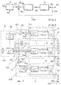
- the heating 2 is implemented by means of three heating stages 21, 22, 23 connected in parallel and each having a heating element; the heating elements of the heating stages 21, 22, 23 are designed, for example, as heating resistors and are connected between the supply voltage V S (for example + 12 V) and the reference potential GND.
- the control device 1 is implemented by means of three parallel-connected linear controllers 11, 12, 13, each heating stage 21, 22, 23 or each heating element being connected to the output of a linear controller 11, 12, 13 and thus with a specific manipulated variable SG (SG1, SG2 , SG3) is applied as a voltage drop at heating stage 21, 22, 23 or the heating element (heating voltage).
- the heating power or the heating voltage as a feedback controlled variable RG (RG1, RG2, RG3) is fed to the comparator 32 from three comparison elements 321, 322, 323, with each linear controller 11, 12, 13 being assigned a comparison element 321, 322, 323; the comparison elements 321, 322, 323 are designed such that each linear controller 11, 12, 13 is acted upon with a certain control difference RD1, RD2, RD3 in such a way that each linear controller 11, 12, 13 has a different control range (only one becomes the linear controller 11, 12, 13 operated in linear mode) and thereby the heating output is continuously controlled without dead areas, overlaps or discontinuities (hysteresis, jump points) in the course of the control.
- the linear controller 11 for the lowest control range is the Command variable FG generated by the setpoint adjuster 31 fed. With the subsequent, next higher control range an additional heating output should only be brought about if the heating power of the underlying control range can no longer be effected can.
- a corresponding one for the next higher controller Generating a benchmark is the difference from that of the Setpoint adjuster 31 predetermined reference variable FG and the in Dependence on this reference variable FG from the first controller 11 generated manipulated variable SG1. Once the first regulator has reached the upper limit of its control range between the command variable FG and the manipulated variable SG1 Difference RD1 no longer from the first controller 11 can be compensated. This difference RD1 that in the Comparative element V1 is determined as the reference variable Controller 12 supplied to the subsequent control range.
- controller 12 can reach its upper limit Control range a further increase in heating output no longer cause.
- a command variable RD1 has been generated is also used for the controller 13 of the next following control area determined.
- the difference supplied to the controller RD1 and that generated in response to this variable by controller 12 Actuating variable SG2 in comparison element V2 is the difference RD2 determined.
- This difference RD2 is the reference variable Regulator 13 fed. In this way, the controller 13 only then an additional heating power if this over the Setpoint adjuster 31 is requested by the controllers 11 and 12 with the respectively connected heating resistors 21 and 22, but can no longer be effected.
- the entire heating area can be designed according to this principle divide into any number of sub-control ranges, and so on for example the average controller power loss low hold.
- the target heating output specified from outside becomes this initially fed to the lowest of the control ranges.
- For one seamless, i.e. continuous transition of the control ranges is the controller for the next higher control ranges only the difference from the next lowest controller supplied target size and the subsequently generated by this Control variable supplied.
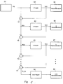
- FIG. 1 A simple circuit diagram to illustrate this principle is shown in Fig. 1.
- Fig. 1 are only the essential Elements of such a heating system for controlling seamless control ranges.
- Target heating power FG is fed to the first controller 61.
- the first controller generates a function of the reference variable FG 61 a manipulated variable SG1, that of the associated with this controller first heating stage 65 is fed.
- This difference RD1 is the second controller 62 supplied.
- the second controller generates in Dependence on the difference RD1 supplied to it Actuating variable SG2, which is the heating power of the second heating level 66 controls.
- the third controller 63 Difference from the difference fed to the second controller 62 RD1 and that of the second controller 62 depending on the Difference RD1 generated manipulated variable SG2 and the third Controller 63 fed as a reference variable.
- the third controller too 63 generates one depending on the difference RD2 Manipulated variable SG3 to the heating power of the third Control heating resistor 67. From the difference RD2 and the Actuating variable SG3 becomes a further difference in comparator V3 formed until finally for the last controller 64 with the connected heating stage 68 the difference RD4 in the comparator V4 is formed.
- the reference variable FG that determines the setpoint value is given in 3 by means of the setpoint adjuster 31, for example in Dependency of the degree of utilization of the generator of the Motor vehicle generated; for example, the leader FG and thus the setpoint specification for the heating output in Dependency of those still available from the generator Output power by means of an externally supplied Generator signal GS varies - for example, the Heating power regulated so that the generator shortly before its Maximum power is operated (for example at 95% of the maximum power).
- the control circuit RK is released or blocked (control activated or deactivated).
- the control circuit RK can thus also with high impedance without adjustment Heating resistors of heating levels 21, 22, 23 and with different resistance values of the heating resistors Heating levels 21, 22, 23 can be realized.
- the maximum value of the command variable FG is based on the sum of the Control limits of the individual linear controllers 11, 12, 13 and thus based on the maximum value of the controlled variable RG.
- the reference variable FG is set using the setpoint adjuster 31 for example depending on the externally supplied Control signal GS varies. Using a setpoint adjuster The control signal SS supplied to the control loop 1 enabled or blocked (the control is activated or deactivated).
- FIG. 7 shows the time profile of the control variables RG1, RG2, RG3 of the individual linear controllers 11, 12, 13 of the control device 1 and the time profile of the control variable RG (overall control profile) of the control device 1 with a continuous increase in the reference variable FG to at their maximum value FG max .
- the values FG 1 , FG 2 and FG 3 of the reference variable FG depend on the structure or type of the respective controller and result from the fact that the controller that is active up to that point can no longer regulate its specified setpoint (ie reaches its controller limit).
- the control circuit RK consisting of (the invisible) control device 1 and the heater 2 (heating stages 21, 22, 23) is integrated in a housing 4.
- the ribs 53 serve to enlarge the surface at the point where the power loss of the power semiconductor components of the control device 1 arises and thus to increase the heating effect.
- the connection of the control circuit RK for the reference potential GND can be made via the housing 4, so that in addition to the signal lines, only the connection for the supply voltage V S has to be provided.
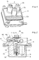
- the housing 4 of the heating system is defined Preheating the (cooling) medium 52 of the cooling circuit 5 one (For example, water-cooled) motor vehicle in the Receiving device 51 of the cooling circuit 5 arranged that the Heating 2 with heating levels 21, 22, 23 or heating elements ins Cooling medium 52 (for example water) immersed and thus from Cooling medium (52) flows around.
- the housing 4 has a Connection part 45 for signal lines, by means of which Heating system external signals can be supplied (for example the control signal SS or the generator signal GS) or output signals provided by the heating system will.
- the semiconductor components of the control device 1 for example the linear regulator 11, 12, 13), in particular the Power semiconductor devices (e.g.
- Power transistors are good on a common thermally conductive support body 42 (for example a Copper plate) applied above the ribs 53 is arranged; the connection between (the Semiconductor components) of the control device 1 and (the Heating elements 21, 22, 23) of heating level 2 is carried out by means of at least one contact connection 24.
- a common thermally conductive support body 42 for example a Copper plate
- the connection between (the Semiconductor components) of the control device 1 and (the Heating elements 21, 22, 23) of heating level 2 is carried out by means of at least one contact connection 24.
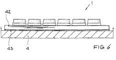
- this common carrier body 42 is arranged on the housing 4 (above the ribs 53); an insulation layer 43 for electrical insulation of the support body 42 and the housing 4 is provided between the support body 42 and the housing 4.
- the other linear regulators 11, 12, 13 are either deactivated (no power loss) or operated in saturation mode are (combined with a low power loss), the effective thermal resistance for the respective linear controller 11, 12, 13 in linear operation corresponding to the number of linear controllers 11, 12, 13 of the control device 1 and thus the temperature load of the semiconductor components (in particular the power transistors) of the control device 1 reduced.
- the heating system is neither on motor vehicles nor on the described embodiment is limited, for example the heating elements of the heating level can also be used with PTC elements will be realized. Instead of cooling water heating the heating system can also be used in other applications Motor vehicle (either circulatory or non-circulatory) are used, for example for the Air heating (interior heating) or for preheating (Diesel) fuel.
Abstract
Description
Die Erfindung bezieht sich auf eine elektrische Heizung gemäß
dem Oberbegriff des Patentanspruches 1.The invention relates to an electric heater according to
the preamble of
Elektrische Heizungen oder Heizsysteme werden beispielsweise in Kraftfahrzeugen für unterschiedliche Anwendungen benötigt, zum Beispiel zur Temperierung (Erwärmung) der Raumluft, zur Vorheizung des Kühlwassers bei wassergekühlten Motoren, zum Vorglühen der Zündkerzen bei selbstzündenden Brennkraftmaschinen, zur Erwärmung von Kraftstoff (Diesel) etc. Üblicherweise bestehen derartige Heizsysteme aus einer Heizung mit mindestens einer Heizstufe, die jeweils mindestens ein (beispielsweise als Heizwiderstand ausgebildetes) Heizelement zur Erzeugung einer bestimmten Heizleistung aufweisen sowie aus einer Kontrolleinheit zur Überwachung des zeitlichen Ablaufs und zur Vorgabe der Heizleistung; Heizung und Kontrolleinheit sind als getrennte Module (Funktionseinheiten) ausgebildet und an verschiedenen Stellen innerhalb des Kraftfahrzeugs angeordnet.Electric heaters or heating systems are for example in Motor vehicles needed for different applications to Example of temperature control (heating) of the room air Preheating the cooling water in water-cooled engines to Preheating the spark plugs for self-igniting Internal combustion engines, for heating fuel (diesel) etc. Such heating systems usually consist of a heater with at least one heating level, each at least one (For example, as a heating resistor) heating element have to generate a certain heating power and from a control unit for monitoring the timing and to specify the heating output; Heating and control unit are designed as separate modules (functional units) and at various points within the motor vehicle arranged.
Nachteilig hierbei ist, daß zum einen eine Vielzahl von Verbindungsleitungen zwischen Heizung und Kontrolleinheit erforderlich ist (verbunden mit Platzbedarf, Kosten, EMV-Problematik) und daß zum anderen die in der Kontrolleinheit entstehende Verlustleistung extra abgeführt werden muß.The disadvantage here is that on the one hand a variety of Connection lines between heating and control unit is required (combined with space requirements, costs, EMC problems) and that on the other hand those in the control unit resulting power loss must be removed separately.
Die Kontrolleinheit kann mittels einer Steuerung der verschiedenen Regler realisiert werden, die beim Auftreten einer Regelabweichung bzw. Regeldifferenz ein unterschiedliches Regelverhalten bewirken; beispielsweise sind Proportionalregler, Integralregler, Differentialregler, Linearregler oder schaltbare Stufenregler gebräuchlich. Um die Belastung der Regeleinrichtung zu reduzieren, kann diese aus mehreren Reglern aufgebaut werden, die üblicherweise als schaltbare Stufenregler ausgebildet sind und beispielsweise durch Schaltvorgänge aktiviert und deaktiviert werden. Problematisch hierbei ist (insbesondere bei Stufenreglern) die Abgrenzung der Wirkungsbereiche der verschiedenen Regler, d.h. der Übergang zwischen den Regelbereichen der Regler ist nicht eindeutig definiert; die Folge hiervon sind Störungen der Regelung bzw. des Regelverhaltens (Auftreten von Totbereichen, Überlappungen, Hysteresen, undefinierten Zuständen etc.) und EMV-Störungen, zu deren Reduzierung kostenintensive Bauelemente erforderlich sind.The control unit can be controlled by means of a various controllers can be realized when they occur a control deviation or control difference a different one Effect control behavior; for example Proportional controller, integral controller, differential controller, Linear controllers or switchable step controllers commonly used. To the To reduce the load on the control device, this can several controllers, which are usually built as switchable step controllers are formed and for example activated and deactivated by switching processes. The problem here is (especially with step controllers) Delimitation of the areas of activity of the various controllers, i.e. the transition between the control ranges of the controllers is not clearly defined; the consequence of this are disturbances of the Regulation or control behavior (occurrence of dead areas, Overlaps, hysteresis, undefined states etc.) and EMC interference, to reduce it cost-intensive components required are.
Der Erfindung liegt die Aufgabe zugrunde, eine einfache elektrische Heizung mit geringer Verlustleistung anzugeben.The invention has for its object a simple electric heating with low power dissipation.
Diese Aufgabe wird erfindungsgemäß durch die Merkmale des
Patentanspruchs 1 gelöst.This object is achieved by the features of
Vorteilhafte Weiterbildungen des Verfahrens sind Bestandteil der weiteren Patentansprüche.Advantageous further developments of the method are part of it of the other claims.
Beim vorgestellten Heizsystem ist die mindestens zwei Heizstufen aufweisende Heizung als Regelstrecke eines Regelkreises ausgebildet, die zusammen mit der Regeleinrichtung des Regelkreises in ein gemeinsames Gehäuse integriert wird. Bei diesem Regelkreis soll die Heizleistung der Heizung (d.h. der Heizstufe/n) als Regelgröße geregelt werden; jedoch wird anstelle der eigentlichen Regelgröße Heizleistung oftmals vorzugsweise eine die Heizleistung bestimmende Größe als tatsächliche Regelgröße herangezogen, d.h. es wird entweder der Strom durch die Heizstufe/n bzw. die Heizelemente (der Heizstrom) oder die Spannung an der/n Heizstufe/n bzw. den Heizelementen (die Heizspannung) geregelt. Bei diesem (beispielsweise spannungsgesteuerten) Regelkreis wird der Sollwert der die Heizleistung bestimmenden Größe (beispielsweise die Heizspannung) vorgegeben, dieser Sollwert mit dem Istwert der die Heizleistung bestimmenden Größe (beispielsweise die Heizspannung) verglichen, und Abweichungen zwischen Sollwert und Istwert (die Regelabweichung bzw. Regeldifferenz) selbsttätig durch Rückkopplung innerhalb des Regelkreises minimiert.In the heating system presented, this is at least two Heater with heating levels as a controlled system Control loop formed together with the control device of the control loop is integrated into a common housing. With this control loop, the heating output of the heating (i.e. the heating level (s) are regulated as a controlled variable; however often instead of the actual controlled variable heating output preferably a variable determining the heating power as actual controlled variable used, i.e. it will either be the Current through the heating stage / s or the heating elements (the Heating current) or the voltage at the heating level (s) Heating elements (the heating voltage) regulated. With this (for example voltage-controlled) control loop Setpoint of the quantity determining the heating output (for example the heating voltage), this setpoint with the actual value of the quantity determining the heating output (e.g. heating voltage) compared, and deviations between setpoint and actual value (the control deviation or Control difference) automatically by feedback within the Control loop minimized.
Als Regeleinrichtung wird vorzugsweise mindestens ein Linearregler eingesetzt; derartige Linearregler (stetige Regler) besitzen in ihrem Regelverlauf keine Unstetigkeiten (im Gegensatz zu einem geschalteten Regler). Beim Einsatz mehrerer Linearregler werden diese derart kaskadiert parallelgeschaltet, daß immer nur jeweils einer der Linearregler im Linearbetrieb betrieben wird und somit das Regelverhalten bestimmt.At least one is preferably used as the control device Linear regulator used; such linear controllers (continuous Controllers) have no discontinuities in their control process (in In contrast to a switched controller). When using several Linear controllers are cascaded in parallel, that only ever one of the linear regulators in linear operation is operated and thus determines the control behavior.
Der Sollwert der Regelgröße Heizleistung bzw. der die Heizleistung bestimmenden Größe kann entweder mittels einer Führungsgröße variiert werden, die beispielsweise mittels eines dem Regelkreis zugeführten externen Eingangssignals generiert wird oder aber mittels eines (beispielsweise im Regelkreis erzeugten) direkten Steuersignals für die Heizleistung bzw. für die die Heizleistung bestimmende Größe.The setpoint of the heating power control variable or the The heating power determining size can be determined either by means of a Reference variable can be varied, for example by means of a external input signal supplied to the control loop or by means of a (for example in the control loop generated) direct control signal for the heating power or for the quantity that determines the heat output.
Die die Regelgröße Heizleistung bzw. die die Heizleistung bestimmende Größe erzeugenden Heizelemente der Heizstufe/n der Heizung (Regelstrecke) sind vorzugsweise als Heizwiderstände ausgebildet. The control variable heating power or the heating power determining size generating heating elements of the heating level / s of Heating (controlled system) are preferably used as heating resistors educated.
Vorzugsweise sind die Halbleiterbauelemente der Regeleinrichtung, insbesondere deren Leistungstransistoren, zur Reduzierung des thermischen Widerstands auf einem gemeinsamen Trägerkörper mit hoher Wärmeleitfähigkeit (beispielsweise auf einer Kupferplatte) aufgebracht.The semiconductor components are preferably the Control device, in particular its power transistors, for Reduction of thermal resistance on a common Carrier body with high thermal conductivity (for example on a copper plate) applied.
Das Heizsystem kann zur Beheizung von an einen Kreislauf gebundenen Medien, d.h. der in einem Wärmekreislauf und/oder in einem Kühlkreislauf des Kraftfahrzeugs befindlichen Medien (beispielsweise Wasser, Luft, Öl, etc.) verwendet werden (beispielsweise für die Kühlwasserbeheizung des Kraftfahrzeugs); alternativ auch zur Beheizung von nicht an einen Kreislauf gebundenen Medien (beispielsweise für die Innenraumbeheizung des Kraftfahrzeugs).The heating system can be used to heat a circuit bound media, i.e. in a heat cycle and / or in media located in a cooling circuit of the motor vehicle (e.g. water, air, oil, etc.) can be used (for example for the cooling water heating of the Motor vehicle); alternatively for heating from not on a cycle - bound media (for example for the Interior heating of the motor vehicle).
Das vorgestellte Heizsystem vereinigt mehrere Vorteile in sich:The heating system presented combines several advantages:
Durch die Integration des Regelkreises aus Regeleinrichtung (Linearregler) und Regelstrecke (Heizung aus Heizstufe/n mit Heizelementen) in einem Gehäuse
- ist das Heizsystem als kompakte funktionsfähige Einheit realisierbar,
- ist keine Abstimmung zwischen der Heizung und einer Kontrolleinheit erforderlich,
- besteht nur ein geringer Aufwand für externe Anschlüsse, die Heizelemente der Heizstufe/n müssen seitens des Anwenders nicht mehr angeschlossen werden;
- wird die Verlustleistung (der Halbleiterbauelemente) der Regeleinrichtung zum Heizen mitverwendet, wodurch man außerdem einen linearen Zusammenhang zwischen dem Heizstrom und der Heizleistung erhält.
- the heating system can be implemented as a compact, functional unit,
- there is no need for coordination between the heating and a control unit,
- there is only little effort for external connections, the heating elements of the heating level / s no longer have to be connected by the user;
- the power loss (of the semiconductor components) of the control device for heating is also used, which also gives a linear relationship between the heating current and the heating power.
Durch die Realisierung der Regeleinrichtung mittels eines Linearreglers oder mittels mehrerer (parallelgeschalteten) Linearregler, von denen jeweils nur einer im Linearbetrieb betrieben wird
- werden Schaltvorgänge vermieden und demzufolge auch die durch Schaltvorgänge bedingten Störungen der Regelung (Auftreten von Totbereichen Überlappungen, Hysteresen, undefinierten Zuständen etc.),
- werden EMV-Störungen weitgehend vermieden, so daß keine kostenintensiven Bauelemente zur Beseitigung der EMV-Problematik benötigt werden.
- switching operations are avoided and consequently also the control malfunctions caused by switching operations (occurrence of dead areas, overlaps, hysteresis, undefined states etc.),
- EMC interference is largely avoided, so that no cost-intensive components are required to eliminate the EMC problem.
Durch den Aufbau der Halbleiterbauelemente der Regeleinrichtung auf einem gemeinsamen Trägerkörper mit hoher Wärmeleitfähigkeit ist eine Reduzierung des thermischen Widerstands der Halbleiterbauelemente der Regeleinrichtung (beispielsweise der Linearregler) und damit der Temperaturbelastung der Halbleiterbauelemente der Regeleinrichtung gegeben.Due to the structure of the semiconductor components of the control device on a common carrier body with high thermal conductivity is a reduction in the thermal resistance of the Semiconductor components of the control device (for example the Linear controller) and thus the temperature load of the Given semiconductor components of the control device.
Im folgenden ist das erfindungsgemäße Heizsystem für das Ausführungsbeispiel der Kühlwasserbeheizung eines Kraftfahrzeugs im Zusammenhang mit der Zeichnung (Figuren 1 bis 7) beschrieben. Es zeigen:
Figur 1- ein Prinzipschaltbild zur Veranschaulichung der Regelung der elektronischen Heizung,
Figur 2- ein Prinzipschaltbild des Regelkreises,
Figur 3- ein Ausführungsbeispiel des Regelkreises,
Figur 4- eine perspektivische Ansicht des Heizsystems,
- Figur 5
- eine Schnittzeichnung des in einen Kühlkreislauf (beispielsweise den Kühlwasserkreislauf) des Kraftfahrzeugs integrierten Heizsystems,
- Figur 6
- eine Anordnung der Halbleiterbauelemente der Regeleinrichtung, und
- Figur 7
- ein Diagramm zur Veranschaulichung des Regelverhaltens.
- Figure 1
- a basic circuit diagram to illustrate the control of the electronic heating,
- Figure 2
- a basic circuit diagram of the control loop,
- Figure 3
- an embodiment of the control loop,
- Figure 4
- a perspective view of the heating system,
- Figure 5
- 1 shows a sectional drawing of the heating system integrated in a cooling circuit (for example the cooling water circuit) of the motor vehicle,
- Figure 6
- an arrangement of the semiconductor components of the control device, and
- Figure 7
- a diagram to illustrate the control behavior.
Die Heizleistung der Heizelemente des Heizsystems soll sowohl dynamisch als auch statisch mit minimalem Fehler eingestellt bzw. vorgegeben werden.The heating power of the heating elements of the heating system should both set dynamically and statically with minimal errors or be specified.
Gemäß Figur 2 wird hierzu innerhalb des spannungsgesteuerten
Regelkreises RK aus Regeleinrichtung 1, Regelstrecke 2 (Heizung
aus mindestens einer Heizstufe mit jeweils mindestens einem
Heizelement) und Sollwerteinsteller 31 die Heizleistung als
Regelgröße RG mittels der Stellgröße SG Spannungsabfall an der
Heizung 2 (Heizspannung) geregelt. Hierzu wird über den
beispielsweise mittels des Steuersignals SS
aktivierbaren/deaktivierbaren Sollwerteinsteller 31
(beispielsweise mittels eines externen Steuersignals GS) eine
Führungsgröße FG erzeugt und diese als Sollwertvorgabe der
Regelgröße RG dem Vergleicher 32 zugeführt ; vom Vergleicher 32
wird diese Sollwertvorgabe der Regelgröße mit dem
(rückgeführten) Istwert der Regelgröße RG verglichen und anhand
dieses Vergleichs die Regeldifferenz RD bzw. die
Regelabweichung gebildet. Diese Regeldifferenz RD bzw.
Regelabweichung wird der Regeleinrichtung 1 (beispielsweise
mindestens ein Linearregler) zugeführt und von dieser die
Stellgröße SG Heizspannung generiert. Mittels der Stellgröße SG
wird die Regelstrecke 2 (Heizung) beaufschlagt und hierdurch
von der Heizung 2 (den Heizstufen bzw. den Heizelementen der
Heizstufen) eine bestimmte Heizleistung als (Istwert der)
Regelgröße RG erzeugt. Die Heizleistung als Regelgröße RG wird
zum einem am Ausgang des Regelkreises RK als Ausgangssignal AS
ausgegeben (dem Kühlwasserkreislauf des Kraftfahrzeugs
zugeführt) und hierdurch eine Heizung des Kühlwassers
vorgenommen und zum andern in der Rückkopplungsschleife des
Regelkreises RK dem Vergleicher 32 als Istwert zugeführt.According to Figure 2, this is done within the voltage controlled
Control circuit RK from
Anstelle der eigentlichen Regelgröße RG Heizleistung wird aus
Gründen der Einfachheit als Regelgröße RG eine der beiden die
Heizleistung bestimmende Größe verwendet, d.h. entweder der
Strom durch die Heizung 2 bzw. die Heizstufen (Heizstrom) oder
der Spannungsabfall an der Heizung 2 bzw. den Heizstufen
(Heizspannung); wird beispielsweise die Heizspannung als
Regelgröße RG verwendet, so ist in diesem Falle die Regelgröße
RG mit der Stellgröße SG identisch.Instead of the actual control variable RG heating power is switched off
For reasons of simplicity, RG is one of the two
Used to determine the heat output, i.e. either the
Current through the
Für ein vereinfachtes Heizungssystem ist zur Steuerung der
Heizleistung ein einfacher Linearregler ohne einen Vergleicher
32 ausreichend.For a simplified heating system is to control the
Heating output a simple linear controller without a
Gemäß Figur 3 ist die Heizung 2 mittels dreier
parallelgeschalteter, jeweils ein Heizelement aufweisenden
Heizstufen 21, 22, 23 realisiert; die Heizelemente der
Heizstufen 21, 22, 23 sind beispielsweise als Heizwiderstände
ausgebildet und zwischen Versorgungsspannung VS (beispielsweise
+ 12 V) und Bezugspotential GND geschaltet. Die
Regeleinrichtung 1 ist mittels dreier parallelgeschalteter
Linearregler 11, 12, 13 realisiert, wobei jede Heizstufe 21,
22, 23 bzw. jedes Heizelement mit dem Ausgang eines
Linearreglers 11, 12, 13 verbunden ist und so mit einer
bestimmten Stellgröße SG (SG1, SG2, SG3) als Spannungsabfall an
der Heizstufe 21, 22, 23 bzw. dem Heizelement (Heizspannung)
beaufschlagt wird. Die Heizleistung bzw. die Heizspannung als
rückgeführte Regelgröße RG (RG1, RG2, RG3) wird dem Vergleicher
32 aus drei Vergleichselementen 321, 322, 323 zugeführt, wobei
jedem Linearregler 11, 12, 13 ein Vergleichselement 321, 322,
323 zugeordnet ist; die Vergleichselemente 321, 322, 323 sind
so ausgebildet, daß jeder Linearregler 11, 12, 13 mit einer
bestimmten Regeldifferenz RD1, RD2, RD3 derart beaufschlagt
wird, daß jeder Linearregler 11, 12, 13 einen anderen
Regelbereich aufweist (es wird nur jeweils einer der
Linearregler 11, 12, 13 im Linearbetrieb betrieben) und
hierdurch eine kontinuierliche Regelung der Heizleistung ohne
Totbereiche, Überlappungen oder Unstetigkeiten (Hysterese,
Sprungstellen) im Regelverlauf erfolgt.According to FIG. 3, the
Dem Linearregler 11 für den niedrigsten Regelbereich wird die
von dem Sollwerteinsteller 31 erzeugte Führungsgröße FG
zugeführt. Mit dem anschließenden, nächst höheren Regelbereich
soll erst dann eine zusätzliche Heizleistung bewirkt werden,
wenn die von der Führungsgröße FG vorgegebene Heizleistung von
dem darunterliegenden Regelbereich nicht mehr bewirkt werden
kann. Um für den nächst höheren Regler eine entsprechende
Führungsgröße zu erzeugen, wird die Differenz aus der von dem
Sollwerteinsteller 31 vorgegebenen Führungsgröße FG und der in
Abhängigkeit von dieser Führungsgröße FG von dem ersten Regler
11 erzeugten Stellgröße SG1 gebildet. Sobald der erste Regler
die Obergrenze seines Regelbereichs erreicht hat, entsteht
zwischen der Führungsgröße FG und der Stellgröße SG1 eine
Differenz RD1, die von dem ersten Regler 11 nicht mehr
ausgeglichen werden kann. Diese Differenz RD1, die in dem
Vergleichselement V1 bestimmt wird, wird als Führungsgröße dem
Regler 12 des anschließenden Regelbereichs zugeführt. Ebenso
kann der Regler 12 bei Erreichen der Obergrenze seines
Regelbereichs eine weitere Zunahme der Heizleistung nicht mehr
bewirken. Nach demselben Prinzip, nach dem für den Regler 12
eine Führungsgröße RD1 erzeugt wurde, wird auch für den Regler
13 des nächstfolgenden Regelbereichs eine Führungsgröße
ermittelt. Dazu wird aus der dem Regler zugeleiteten Differenz
RD1 und der als Antwort auf diese Größe vom Regler 12 erzeugten
Stellgröße SG2 im Vergleichselement V2 die Differenz RD2
ermittelt. Diese Differenz RD2 wird als Führungsgröße dem
Regler 13 zugeleitet. Auf diese Weise bewirkt der Regler 13
erst dann eine zusätzliche Heizleistung, wenn diese über den
Sollwerteinsteller 31 angefordert wird, von den Reglern 11 und
12 mit den jeweils angeschlossenen Heizwiderständen 21 und 22,
aber nicht mehr bewirkt werden kann.The
Diesem Prinzip entsprechend läßt sich der gesamte Heizbereich in eine beliebige Zahl von Teil-Regelbereichen aufteilen, um so beispielsweise die mittlere Reglerverlustleistung niedrig zu halten. Die von außen vorgegebene Soll-Heizleistung wird dazu zunächst dem niedrigsten der Regelbereiche zugeführt. Für einen nahtlosen, d.h. kontinuierlichen Übergang der Regelbereiche wird den Reglern für die nächst höheren Regelbereiche jeweils nur die Differenz aus der dem jeweils nächst niedrigen Regler zugeführten Sollgröße und der von diesem daraufhin erzeugten Stellgröße zugeführt.The entire heating area can be designed according to this principle divide into any number of sub-control ranges, and so on for example the average controller power loss low hold. The target heating output specified from outside becomes this initially fed to the lowest of the control ranges. For one seamless, i.e. continuous transition of the control ranges is the controller for the next higher control ranges only the difference from the next lowest controller supplied target size and the subsequently generated by this Control variable supplied.
Ein einfacheres Schaltbild zur Verdeutlichung dieses Prinzips ist in Fig. 1 dargestellt. In Fig. 1 sind nur die wesentlichen Elemente eines solchen Heizsystems zur Steuerung von übergangslosen Regelbereichen wiedergegeben.A simple circuit diagram to illustrate this principle is shown in Fig. 1. In Fig. 1 are only the essential Elements of such a heating system for controlling seamless control ranges.
Die von außen (z.B. vom Sollwerteinsteller 31) vorgegebene
Soll-Heizleistung FG wird dem ersten Regler 61 zugeführt. In
Abhängigkeit von der Führungsgröße FG erzeugt der erste Regler
61 eine Stellgröße SG1, die der mit diesem Regler verbundenen
ersten Heizstufe 65 zugeleitet wird. Eine Differenz, die
entsteht, wenn der erste Regler 61 mit seiner Stellgröße SG1
einer weiteren Erhöhung der Führungsgröße FG durch den
Sollwerteinsteller 31 nicht mehr folgen kann, wird im
Vergleichselement V1 gebildet. Diese Differenz RD1 wird dem
zweiten Regler 62 zugeführt. Der zweite Regler erzeugt in
Abhängigkeit von der ihm zugeleiteten Differenz RD1 eine
Stellgröße SG2, welche die Heizleistung der zweiten Heizstufe
66 steuert. Zur Steuerung des dritten Reglers 63 wird die
Differenz aus der dem zweiten Regler 62 zugeleiteten Differenz
RD1 und der von dem zweiten Regler 62 in Abhängigkeit von der
Differenz RD1 erzeugten Stellgröße SG2 gebildet und dem dritten
Regler 63 als Führungsgröße zugeleitet. Auch der dritte Regler
63 erzeugt in Abhängigkeit von der Differenz RD2 eine
Stellgröße SG3, um die Heizleistung des dritten
Heizwiderstandes 67 zu steuern. Aus der Differenz RD2 und der
Stellgröße SG3 wird im Vergleicher V3 eine weitere Differenz
gebildet, bis abschließend für den letzten Regler 64 mit der
angeschlossenen Heizstufe 68 die Differenz RD4 im Vergleicher
V4 gebildet wird.The one specified from outside (e.g. by the setpoint adjuster 31)
Target heating power FG is fed to the
Die die Sollwertvorgabe bestimmende Führungsgröße FG wird in
Figur 3 mittels des Sollwerteinstellers 31 beispielsweise in
Abhängigkeit des Auslastungsgrads des Generators des
Kraftfahrzeugs generiert; beispielsweise wird die Führungsgröße
FG und damit die Sollwertvorgabe für die Heizleistung in
Abhängigkeit der vom Generator noch zur Verfügung stellbaren
Ausgangsleistung mittels eines extern zugeführten
Generatorsignals GS variiert - beispielsweise wird die
Heizleistung so geregelt, daß der Generator kurz vor seinem
Leistungsmaximum betrieben wird (beispielsweise bei 95 % der
maximalen Leistung). Mittels eines dem Sollwerteinsteller 31
zugeführten Steuersignals SS wird der Regelkreis RK freigegeben
oder gesperrt (die Regelung aktiviert oder deaktiviert). Da die
als Heizelemente verwendeten Heizwiderstände der Heizstufen 21,
22, 23 gegen Bezugspotential GND (Masse) geschaltet sind und
die über diesen Heizwiderständen abfallende Spannung (die
Heizspannung) als Stellgröße verwendet wird, sind keine
Strommeßwiderstände erforderlich; weiterhin ist die Regelung
auch unempfindlich gegenüber Toleranzen der Widerstandswerte,
der Regelkreis RK kann somit ohne Abgleich auch mit hochohmigen
Heizwiderständen der Heizstufen 21, 22, 23 und mit
unterschiedlichen Widerstandswerten der Heizwiderstände der
Heizstufen 21, 22, 23 realisiert werden.The reference variable FG that determines the setpoint value is given in
3 by means of the
Die parallelgeschalteten kaskadierten Linearregler 11, 12, 13
der Regeleinrichtung 10 werden mit unterschiedlichen, anhand
der Differenz aus jeweiliger Führungsgröße FG1, FG2, FG3
(Sollwert) und jeweiliger Regelgröße RG1, RG2, RG3 (Istwert)
generierten Regeldifferenzen RD1, RD2, RD3 beaufschlagt:
Der Maximalwert der Führungsgröße FG wird anhand der Summe der
Regelgrenzen der einzelnen Linearregler 11, 12, 13 und damit
anhand des Maximalwerts der Regelgröße RG vorgegeben. Die
Führungsgröße FG wird mittels des Sollwerteinstellers 31
beispielsweise in Abhängigkeit von dem extern zugeführten
Steuersignals GS variiert. Mittels eines dem Sollwerteinsteller
31 zugeführten Steuersignals SS wird der Regelkreis 1
freigegeben oder gesperrt (die Regelung aktiviert oder
deaktiviert).The maximum value of the command variable FG is based on the sum of the
Control limits of the individual
In der Figur 7 ist der zeitliche Verlauf der Regelgrößen RG1,
RG2, RG3 der einzelnen Linearregler 11, 12, 13 der
Regeleinrichtung 1 und der zeitlich Verlauf der Regelgröße RG
(Gesamtregelverlauf) der Regeleinrichtung 1 bei einer von Null
beginnenden kontinuierlichen Erhöhung der Führungsgröße FG bis
zu ihrem Maximalwert FGmax dargestellt.FIG. 7 shows the time profile of the control variables RG1, RG2, RG3 of the individual
Aufgrund der Vorgabe unterschiedlicher Regeldifferenzen RD1,
RD2, RD3 werden die parallelgeschalteten kaskadierten
Linearregler 11, 12, 13 der Regeleinrichtung 1 bei dieser
kontinuierlichen Erhöhung der Führungsgröße FG sukzessive
aktiviert und bestimmen hierdurch auch sukzessive den Verlauf
der als Summe der Regelgrößen RG1, RG2, RG3 der Linearregler
11, 12, 13 gebildeten Regelgröße RG (
Wie der Figur 7 zu entnehmen ist, wird jeweils nur einer der
Linearregler 11, 12, 13 der Regeleinrichtung 1 im Linearbetrieb
betrieben, so daß bei einer Variation der Führungsgröße FG eine
kontinuierliche Regelung der Regelgröße RG ohne Unstetigkeiten
(Hysterese, Sprungstellen), Totbereiche oder Überlappungen
erfolgt.As can be seen in Figure 7, only one of the
Die Werte FG1, FG2 und FG3 der Führungsgröße FG sind vom Aufbau bzw. Typ des jeweiligen Reglers abhängig und ergeben sich dadurch, daß der bis dort wirksame Regler seinen vorgegebenen Sollwert nicht mehr ausregeln kann (d.h. seine Reglergrenze erreicht).The values FG 1 , FG 2 and FG 3 of the reference variable FG depend on the structure or type of the respective controller and result from the fact that the controller that is active up to that point can no longer regulate its specified setpoint (ie reaches its controller limit).
Gemäß Figur 4 mit einer perspektivischen Darstellung des
Heizsystems ist der Regelkreis RK aus (der nicht sichtbaren)
Regeleinrichtung 1 und der Heizung 2 (Heizstufen 21, 22, 23) in
einem Gehäuse 4 integriert. Die Rippen 53 dienen zur
Vergrößerung der Oberfläche an der Stelle, wo die
Verlustleistung der Leistungs-Halbleiterbauelemente der
Regeleinrichtung 1 entsteht und damit zur Erhöhung der
Heizwirkung. Der Anschluß des Regelkreises RK für das
Bezugspotential GND (der Masseanschluß) kann über das Gehäuse 4
geführt werden, so daß außer den Signalleitungen nur der
Anschuß für die Versorgungsspannung VS vorgesehen werden muß.According to FIG. 4 with a perspective representation of the heating system, the control circuit RK consisting of (the invisible)
Gemäß Figur 5 ist das Gehäuse 4 des Heizsystems zur definierten
Vorheizung des (Kühl)Mediums 52 des Kühlkreislaufs 5 eines
(beispielsweise wassergekühlten) Kraftfahrzeugs derart in der
Aufnahmevorrichtung 51 des Kühlkreislaufs 5 angeordnet, daß die
Heizung 2 mit den Heizstufen 21, 22, 23 bzw. Heizelementen ins
Kühlmedium 52 (beispielsweise Wasser) eintaucht und somit vom
Kühlmedium (52) umströmt wird. Das Gehäuse 4 weist ein
Anschlußteil 45 für Signalleitungen auf, mittels dem dem
Heizsystem externe Signale zugeführt werden können
(beispielsweise das Steuersignal SS oder das Generatorsignal
GS) oder vom Heizsystem Ausgangssignale zur Verfügung gestellt
werden. Die Halbleiterbauelemente der Regeleinrichtung 1
(beispielsweise der Linearregler 11, 12, 13), insbesondere die
Leistungs-Halbleiterbauelemente (beispielsweise
Leistungstransistoren) sind auf einem gemeinsamen gut
wärmeleitenden Trägerkörper 42 (beispielsweise eine
Kupferplatte) aufgebracht, der oberhalb der Rippen 53
angeordnet ist; die Verbindung zwischen (den
Halbleiterbauelementen) der Regeleinrichtung 1 und (den
Heizelementen 21, 22, 23) der Heizstufe 2 erfolgt mittels
mindestens einer Kontaktverbindung 24.According to Figure 5, the
Da die Heizelemente der Heizstufen 21, 22, 23 (die
Heizwiderstände) gegen Bezugspotential GND (Masse) geschaltet
sind und die Gehäuse der Leistungs-Halbleiterbauelemente
(beispielsweise der Leistungstransistoren) der Regeleinrichtung
1 somit alle auf gleichem Potential (Versorgungsspannung VS)
liegen, können die Halbleiterbauelemente der Regeleinrichtung 1
auf einen gemeinsamen Trägerkörper 42 aufgebracht werden. Gemäß
Figur 6 ist dieser gemeinsame Trägerkörper 42 auf dem Gehäuse 4
(oberhalb der Rippen 53) angeordnet; zwischen Trägerkörper 42
und Gehäuse 4 ist eine Isolationsschicht 43 zur elektrischen
Isolation von Trägerkörper 42 und Gehäuse 4 vorgesehen. Da
immer nur jeweils einer der Linearregler 11, 12, 13 im
Linearbetrieb betrieben wird (und daher nur bei diesem
Linearregler eine große Verlustleistung entsteht), die jeweils
anderen Linearregler 11, 12, 13 dagegen entweder deaktiviert
sind (keine Verlustleistung) oder im Sättigungsbetrieb
betrieben werden (verbunden mit einer geringen
Verlustleistung), wird durch den gemeinsamen Trägerkörper 42
der wirksame thermische Widerstand für den jeweiligen
Linearregler 11, 12, 13 im Linearbetrieb entsprechend der
Anzahl der vorgesehenen Linearregler 11, 12, 13 der
Regeleinrichtung 1 und damit die Temperaturbelastung der
Halbleiterbauelemente (insbesondere der Leistungstransistoren)
der Regeleinrichtung 1 reduziert.Since the heating elements of the heating stages 21, 22, 23 (the heating resistors) are connected to reference potential GND (ground) and the housings of the power semiconductor components (for example the power transistors) of the
Das Heizsystem ist jedoch weder auf Kraftfahrzeuge, noch auf das beschriebene Ausführungsbeispiel beschränkt, beispielsweise können die Heizelemente der Heizstufe auch mittels PTC-Elementen realisiert werden. Anstelle einer Kühlwasserbeheizung kann das Heizsystem auch für andere Anwendungsfälle im Kraftfahrzeug (entweder kreislaufgebunden oder nichtkreislaufgebunden) eingesetzt werden, beispielsweise für die Erwärmung der Luft (Innenraumbeheizung) oder zur Vorheizung von (Diesel)-Kraftstoff.However, the heating system is neither on motor vehicles nor on the described embodiment is limited, for example the heating elements of the heating level can also be used with PTC elements will be realized. Instead of cooling water heating the heating system can also be used in other applications Motor vehicle (either circulatory or non-circulatory) are used, for example for the Air heating (interior heating) or for preheating (Diesel) fuel.
Claims (5)
gekennzeichnet durch
marked by
dadurch gekennzeichnet,
characterized by
dadurch gekennzeichnet,
characterized by
dadurch gekennzeichnet,
characterized by
Applications Claiming Priority (4)
| Application Number | Priority Date | Filing Date | Title |
|---|---|---|---|
| DE19642443A DE19642443C2 (en) | 1996-10-15 | 1996-10-15 | Process for controlling a controlled variable |
| DE1996142442 DE19642442C5 (en) | 1996-10-15 | 1996-10-15 | Heating system for motor vehicles |
| DE19642443 | 1996-10-15 | ||
| DE19642442 | 1996-10-15 |
Publications (3)
| Publication Number | Publication Date |
|---|---|
| EP0837381A2 true EP0837381A2 (en) | 1998-04-22 |
| EP0837381A3 EP0837381A3 (en) | 1999-06-02 |
| EP0837381B1 EP0837381B1 (en) | 2002-03-06 |
Family
ID=26030359
Family Applications (1)
| Application Number | Title | Priority Date | Filing Date |
|---|---|---|---|
| EP19970117886 Expired - Lifetime EP0837381B1 (en) | 1996-10-15 | 1997-10-15 | Electrical heating |
Country Status (4)
| Country | Link |
|---|---|
| US (1) | US5990459A (en) |
| EP (1) | EP0837381B1 (en) |
| JP (1) | JPH10187204A (en) |
| DE (1) | DE59706540D1 (en) |
Cited By (6)
| Publication number | Priority date | Publication date | Assignee | Title |
|---|---|---|---|---|
| EP1026020A1 (en) * | 1999-02-08 | 2000-08-09 | Valeo Klimasysteme GmbH | Electric heating device for a vehicle |
| DE19946339C1 (en) * | 1999-09-28 | 2000-08-31 | Daimler Chrysler Ag | Method for regulating automatic electrical heating and air conditioning machinery includes a booster heater with different heating elements triggered independently of each other. |
| EP1091621A1 (en) * | 1999-10-07 | 2001-04-11 | Alcatel | Electric heater and method for controlling the same |
| EP1157868A2 (en) | 2000-05-23 | 2001-11-28 | Catem GmbH & Co.KG | Electrical heating device |
| WO2002045985A2 (en) * | 2000-12-09 | 2002-06-13 | Eichenauer Heizelemente Gmbh & Co. Kg | Method and device for controlling the temperature of an electric heater that functions with a positive temperature coefficient (ptc) heating element |
| EP1530405A2 (en) | 1997-09-02 | 2005-05-11 | Behr GmbH & Co. KG | Electrical heating device, particularly for motor vehicles |
Families Citing this family (22)
| Publication number | Priority date | Publication date | Assignee | Title |
|---|---|---|---|---|
| FR2813559B1 (en) * | 2000-09-04 | 2002-11-29 | Renault | DEVICE FOR HEATING THE INTERIOR OF A MOTOR VEHICLE |
| DE10065400C2 (en) * | 2000-12-27 | 2003-08-14 | Siemens Ag | Flow pump with high temperature superconductor and thus operated superconducting electromagnet |
| DE10102671C2 (en) * | 2001-01-17 | 2003-12-24 | Eichenauer Heizelemente Gmbh | Electric heating for a motor vehicle |
| DE10208103A1 (en) * | 2002-02-26 | 2003-09-11 | Beru Ag | Electric air heating device, in particular for a motor vehicle |
| DE10214166A1 (en) * | 2002-03-28 | 2003-10-23 | David & Baader Gmbh | Heating flange, in particular for preheating air in an intake line of an internal combustion engine |
| EP1651911A4 (en) * | 2003-07-28 | 2010-09-01 | Phillips & Temro Ind Inc | Controller for air intake heater |
| US20060196484A1 (en) * | 2003-07-28 | 2006-09-07 | Gill Alan P | Capture and burn air heater |
| US8003922B2 (en) * | 2006-02-17 | 2011-08-23 | Phillips & Temro Industries Inc. | Solid state switch with over-temperature and over-current protection |
| US8981264B2 (en) * | 2006-02-17 | 2015-03-17 | Phillips & Temro Industries Inc. | Solid state switch |
| ES2349351T3 (en) * | 2007-07-20 | 2010-12-30 | EBERSPÄCHER CATEM GMBH & CO. KG | ELECTRICAL HEATING DEVICE IN SPECIAL FOR MOTOR VEHICLES. |
| US8218955B2 (en) * | 2008-12-30 | 2012-07-10 | Hatco Corporation | Method and system for reducing response time in booster water heating applications |
| DE202009003807U1 (en) * | 2009-03-20 | 2010-08-12 | Voss Automotive Gmbh | Electric heating system for a fluid line system |
| KR101082722B1 (en) * | 2009-09-24 | 2011-11-10 | (주)엘지하우시스 | A Heat Control Device of Generating Heat Glass |
| JP2011152907A (en) * | 2010-01-28 | 2011-08-11 | Mitsubishi Heavy Ind Ltd | Electric heating system and vehicular air conditioner |
| DE102011002144A1 (en) | 2011-02-25 | 2012-08-30 | Dbk David + Baader Gmbh | Method for actuating electric heater used in motor car, involves resistance heating element to which power supply is reduced or shutdown, when measured resistance is greater than or equal to positive temperature coefficient resistor |
| US9345068B2 (en) | 2012-07-26 | 2016-05-17 | Hewlett-Packard Development Company, L.P. | Electrical resistor heating |
| DE102012109801B4 (en) * | 2012-10-15 | 2015-02-05 | Borgwarner Ludwigsburg Gmbh | Electric heater |
| US10221817B2 (en) | 2016-05-26 | 2019-03-05 | Phillips & Temro Industries Inc. | Intake air heating system for a vehicle |
| US10077745B2 (en) | 2016-05-26 | 2018-09-18 | Phillips & Temro Industries Inc. | Intake air heating system for a vehicle |
| US10585411B2 (en) * | 2018-02-06 | 2020-03-10 | Ford Global Technologies, Llc | Vehicle power supply control using serial communication |
| US10969141B2 (en) | 2018-03-13 | 2021-04-06 | Ngb Innovations Llc | Regulating temperature and reducing buildup in a water heating system |
| CN114675625A (en) * | 2022-03-21 | 2022-06-28 | 潍柴动力股份有限公司 | Controller control method and device |
Citations (5)
| Publication number | Priority date | Publication date | Assignee | Title |
|---|---|---|---|---|
| US3659186A (en) * | 1968-09-04 | 1972-04-25 | Hitachi Ltd | Control and protection arrangement for a d.c. power transmission system |
| US3710139A (en) * | 1967-04-24 | 1973-01-09 | Sybron Corp | Amplifier system |
| US4151589A (en) * | 1978-02-03 | 1979-04-24 | Leeds & Northrup Company | Decoupled cascade control system |
| EP0057477A2 (en) * | 1981-01-30 | 1982-08-11 | Werkzeugmaschinenfabrik Oerlikon-Bührle AG | Control circuit with balancing device |
| GB2151820A (en) * | 1984-01-10 | 1985-07-24 | Gary Miller | Multiple loop feedback systems |
Family Cites Families (8)
| Publication number | Priority date | Publication date | Assignee | Title |
|---|---|---|---|---|
| US4138607A (en) * | 1977-06-24 | 1979-02-06 | Pako Corporation | Dual priority temperature control |
| DE3447182A1 (en) * | 1984-12-22 | 1986-06-26 | Kromberg & Schubert, 5600 Wuppertal | Heater for the passenger compartment in motor vehicles |
| JP2727319B2 (en) * | 1988-02-05 | 1998-03-11 | 富士写真フイルム株式会社 | Temperature control device |
| FR2690112B1 (en) * | 1992-04-21 | 1995-06-23 | Valeo Thermique Habitacle | DEVICE FOR HEATING-VENTILATION OF THE INTERIOR OF A MOTOR VEHICLE POWERED BY A LOW-THERMAL EMISSION ENGINE. |
| JP3155393B2 (en) * | 1993-05-13 | 2001-04-09 | 富士写真フイルム株式会社 | Drying equipment for photosensitive material processing equipment |
| DE4345056C2 (en) * | 1993-12-31 | 1996-07-11 | Eberspaecher J | Vehicle heater with control unit |
| US5521359A (en) * | 1995-04-18 | 1996-05-28 | Bone; Charles A. | System for coordinating operation of microwave oven with a second appliance |
| US5658480A (en) * | 1995-09-05 | 1997-08-19 | Therm-O-Disc, Incorporated | Heating element control |
-
1997
- 1997-10-14 US US08/949,639 patent/US5990459A/en not_active Expired - Lifetime
- 1997-10-15 EP EP19970117886 patent/EP0837381B1/en not_active Expired - Lifetime
- 1997-10-15 JP JP28227497A patent/JPH10187204A/en active Pending
- 1997-10-15 DE DE59706540T patent/DE59706540D1/en not_active Expired - Lifetime
Patent Citations (5)
| Publication number | Priority date | Publication date | Assignee | Title |
|---|---|---|---|---|
| US3710139A (en) * | 1967-04-24 | 1973-01-09 | Sybron Corp | Amplifier system |
| US3659186A (en) * | 1968-09-04 | 1972-04-25 | Hitachi Ltd | Control and protection arrangement for a d.c. power transmission system |
| US4151589A (en) * | 1978-02-03 | 1979-04-24 | Leeds & Northrup Company | Decoupled cascade control system |
| EP0057477A2 (en) * | 1981-01-30 | 1982-08-11 | Werkzeugmaschinenfabrik Oerlikon-Bührle AG | Control circuit with balancing device |
| GB2151820A (en) * | 1984-01-10 | 1985-07-24 | Gary Miller | Multiple loop feedback systems |
Cited By (10)
| Publication number | Priority date | Publication date | Assignee | Title |
|---|---|---|---|---|
| EP1530405A2 (en) | 1997-09-02 | 2005-05-11 | Behr GmbH & Co. KG | Electrical heating device, particularly for motor vehicles |
| DE19738318C5 (en) * | 1997-09-02 | 2014-10-30 | Behr Gmbh & Co. Kg | Electric heating device for a motor vehicle |
| EP1026020A1 (en) * | 1999-02-08 | 2000-08-09 | Valeo Klimasysteme GmbH | Electric heating device for a vehicle |
| US6559426B2 (en) | 1999-02-08 | 2003-05-06 | Valeo Klimasysteme Gmbh | Electric heating device for a vehicle |
| DE19946339C1 (en) * | 1999-09-28 | 2000-08-31 | Daimler Chrysler Ag | Method for regulating automatic electrical heating and air conditioning machinery includes a booster heater with different heating elements triggered independently of each other. |
| EP1091621A1 (en) * | 1999-10-07 | 2001-04-11 | Alcatel | Electric heater and method for controlling the same |
| EP1157868A2 (en) | 2000-05-23 | 2001-11-28 | Catem GmbH & Co.KG | Electrical heating device |
| EP1157869A2 (en) | 2000-05-23 | 2001-11-28 | Catem GmbH & Co.KG | Additional electrical heating device for vehicles |
| WO2002045985A2 (en) * | 2000-12-09 | 2002-06-13 | Eichenauer Heizelemente Gmbh & Co. Kg | Method and device for controlling the temperature of an electric heater that functions with a positive temperature coefficient (ptc) heating element |
| WO2002045985A3 (en) * | 2000-12-09 | 2002-12-27 | Beru Ag | Method and device for controlling the temperature of an electric heater that functions with a positive temperature coefficient (ptc) heating element |
Also Published As
| Publication number | Publication date |
|---|---|
| EP0837381B1 (en) | 2002-03-06 |
| EP0837381A3 (en) | 1999-06-02 |
| DE59706540D1 (en) | 2002-04-11 |
| JPH10187204A (en) | 1998-07-14 |
| US5990459A (en) | 1999-11-23 |
Similar Documents
| Publication | Publication Date | Title |
|---|---|---|
| EP0837381B1 (en) | Electrical heating | |
| EP1986322B1 (en) | Semiconductor switch with integrated delay circuit | |
| EP2123130A1 (en) | Drive device and method for operating at least one series circuit of light-emitting diodes | |
| DE69636406T2 (en) | VOLTAGE REGULATING MODULE WITH AN EXTENSION POSSIBILITY | |
| DE102005022569A1 (en) | System for generating electric power for vehicles | |
| DE10347426B4 (en) | A method of controlling the idle speed of a combustion engine driving a voltage generator | |
| DE19642442C5 (en) | Heating system for motor vehicles | |
| EP1675245A2 (en) | Circuitry for the rapid reduction of the freewheeling current passing through the field winding of an alternator | |
| DE3837071C1 (en) | ||
| DE19813797A1 (en) | Device for controlling the flow of current through a series of inductive loads | |
| EP0314681B1 (en) | Final stage of a bridge circuit | |
| DE102010008583A1 (en) | Heating control system | |
| EP0708998B1 (en) | Buffered d.c. power supply | |
| DE3623651C2 (en) | Method and circuit arrangement for determining an actuator setpoint | |
| DE112018006766T5 (en) | LED luminance control circuit, LED luminance control method and LED luminance control program | |
| DE4300953A1 (en) | Temp.-stabilised electronic ignition for IC engine - has series opposition Zener diodes between base of control transistor and earth | |
| DE2241621B2 (en) | INTEGRATED VOLTAGE REGULATION DEVICE | |
| DE2649306A1 (en) | VOLTAGE REGULATORS FOR GENERATORS IN MOTOR VEHICLES | |
| DE10315303B4 (en) | Semiconductor device power supply for system with at least two, in particular stacked, semiconductor devices | |
| EP0932856B1 (en) | Control loop for controlling at least two controlled variables | |
| DE102011084230A1 (en) | Method for operating a converter for a starter motor | |
| DE102016007752A1 (en) | Protection circuit, lighting arrangement and operating method | |
| DE102007043516A1 (en) | Electronic camera module operating arrangement for use in motor vehicle, has voltage controlling block arranged in thermal contact with camera module, where power loss of controlling block is controlled by input voltage of controlling block | |
| EP0285814B1 (en) | Variable parallel interface, particularly for a screwing machine | |
| WO2000031603A1 (en) | Circuit for producing a stabilised supply voltage for a plurality of users |
Legal Events
| Date | Code | Title | Description |
|---|---|---|---|
| PUAI | Public reference made under article 153(3) epc to a published international application that has entered the european phase |
Free format text: ORIGINAL CODE: 0009012 |
|
| AK | Designated contracting states |
Kind code of ref document: A2 Designated state(s): DE FR GB IT SE |
|
| PUAL | Search report despatched |
Free format text: ORIGINAL CODE: 0009013 |
|
| AK | Designated contracting states |
Kind code of ref document: A3 Designated state(s): AT BE CH DE DK ES FI FR GB GR IE IT LI LU MC NL PT SE |
|
| 17P | Request for examination filed |
Effective date: 19991123 |
|
| AKX | Designation fees paid |
Free format text: DE FR GB IT SE |
|
| 17Q | First examination report despatched |
Effective date: 20000901 |
|
| GRAG | Despatch of communication of intention to grant |
Free format text: ORIGINAL CODE: EPIDOS AGRA |
|
| GRAG | Despatch of communication of intention to grant |
Free format text: ORIGINAL CODE: EPIDOS AGRA |
|
| GRAH | Despatch of communication of intention to grant a patent |
Free format text: ORIGINAL CODE: EPIDOS IGRA |
|
| GRAH | Despatch of communication of intention to grant a patent |
Free format text: ORIGINAL CODE: EPIDOS IGRA |
|
| REG | Reference to a national code |
Ref country code: GB Ref legal event code: IF02 |
|
| GRAA | (expected) grant |
Free format text: ORIGINAL CODE: 0009210 |
|
| AK | Designated contracting states |
Kind code of ref document: B1 Designated state(s): DE FR GB IT SE |
|
| GBT | Gb: translation of ep patent filed (gb section 77(6)(a)/1977) |
Effective date: 20020307 |
|
| REF | Corresponds to: |
Ref document number: 59706540 Country of ref document: DE Date of ref document: 20020411 |
|
| ET | Fr: translation filed | ||
| PLBQ | Unpublished change to opponent data |
Free format text: ORIGINAL CODE: EPIDOS OPPO |
|
| PLBI | Opposition filed |
Free format text: ORIGINAL CODE: 0009260 |
|
| PLBF | Reply of patent proprietor to notice(s) of opposition |
Free format text: ORIGINAL CODE: EPIDOS OBSO |
|
| 26 | Opposition filed |
Opponent name: BERU AG Effective date: 20021204 |
|
| PLBF | Reply of patent proprietor to notice(s) of opposition |
Free format text: ORIGINAL CODE: EPIDOS OBSO |
|
| PLCK | Communication despatched that opposition was rejected |
Free format text: ORIGINAL CODE: EPIDOSNREJ1 |
|
| APBP | Date of receipt of notice of appeal recorded |
Free format text: ORIGINAL CODE: EPIDOSNNOA2O |
|
| APAH | Appeal reference modified |
Free format text: ORIGINAL CODE: EPIDOSCREFNO |
|
| APBU | Appeal procedure closed |
Free format text: ORIGINAL CODE: EPIDOSNNOA9O |
|
| PLBN | Opposition rejected |
Free format text: ORIGINAL CODE: 0009273 |
|
| STAA | Information on the status of an ep patent application or granted ep patent |
Free format text: STATUS: OPPOSITION REJECTED |
|
| 27O | Opposition rejected |
Effective date: 20060502 |
|
| REG | Reference to a national code |
Ref country code: DE Ref legal event code: R082 Ref document number: 59706540 Country of ref document: DE Representative=s name: WINTER, BRANDL, FUERNISS, HUEBNER, ROESS, KAIS, DE |
|
| REG | Reference to a national code |
Ref country code: DE Ref legal event code: R082 Ref document number: 59706540 Country of ref document: DE Representative=s name: WINTER, BRANDL, FUERNISS, HUEBNER, ROESS, KAIS, DE Effective date: 20130612 Ref country code: DE Ref legal event code: R082 Ref document number: 59706540 Country of ref document: DE Representative=s name: WINTER, BRANDL, FUERNISS, HUEBNER, ROESS, KAIS, DE Effective date: 20130717 Ref country code: DE Ref legal event code: R081 Ref document number: 59706540 Country of ref document: DE Owner name: DBK DAVID + BAADER GMBH, DE Free format text: FORMER OWNERS: ALCATEL-LUCENT DEUTSCHLAND AG, 70435 STUTTGART, DE; DBK DAVID + BAADER GMBH, 76870 KANDEL, DE Effective date: 20130717 Ref country code: DE Ref legal event code: R081 Ref document number: 59706540 Country of ref document: DE Owner name: ALCATEL-LUCENT DEUTSCHLAND AG, DE Free format text: FORMER OWNERS: ALCATEL-LUCENT DEUTSCHLAND AG, 70435 STUTTGART, DE; DBK DAVID + BAADER GMBH, 76870 KANDEL, DE Effective date: 20130717 Ref country code: DE Ref legal event code: R081 Ref document number: 59706540 Country of ref document: DE Owner name: ALCATEL-LUCENT DEUTSCHLAND AG, DE Free format text: FORMER OWNER: ALCATEL-LUCENT DEUTSCHLAND AG, DBK DAVID + BAADER GMBH, , DE Effective date: 20130717 Ref country code: DE Ref legal event code: R081 Ref document number: 59706540 Country of ref document: DE Owner name: DBK DAVID + BAADER GMBH, DE Free format text: FORMER OWNER: ALCATEL-LUCENT DEUTSCHLAND AG, DBK DAVID + BAADER GMBH, , DE Effective date: 20130717 Ref country code: DE Ref legal event code: R081 Ref document number: 59706540 Country of ref document: DE Owner name: DBK DAVID + BAADER GMBH, DE Free format text: FORMER OWNER: DBK DAVID + BAADER GMBH, 76870 KANDEL, DE Effective date: 20130612 Ref country code: DE Ref legal event code: R081 Ref document number: 59706540 Country of ref document: DE Owner name: ALCATEL-LUCENT DEUTSCHLAND AG, DE Free format text: FORMER OWNER: DBK DAVID + BAADER GMBH, 76870 KANDEL, DE Effective date: 20130612 |
|
| REG | Reference to a national code |
Ref country code: FR Ref legal event code: PLFP Year of fee payment: 19 |
|
| REG | Reference to a national code |
Ref country code: FR Ref legal event code: PLFP Year of fee payment: 20 |
|
| REG | Reference to a national code |
Ref country code: DE Ref legal event code: R082 Ref document number: 59706540 Country of ref document: DE Representative=s name: WINTER, BRANDL - PARTNERSCHAFT MBB, PATENTANWA, DE Ref country code: DE Ref legal event code: R082 Ref document number: 59706540 Country of ref document: DE Representative=s name: WINTER, BRANDL, FUERNISS, HUEBNER, ROESS, KAIS, DE |
|
| PGFP | Annual fee paid to national office [announced via postgrant information from national office to epo] |
Ref country code: FR Payment date: 20161025 Year of fee payment: 20 Ref country code: GB Payment date: 20161025 Year of fee payment: 20 Ref country code: DE Payment date: 20160930 Year of fee payment: 20 |
|
| PGFP | Annual fee paid to national office [announced via postgrant information from national office to epo] |
Ref country code: SE Payment date: 20161025 Year of fee payment: 20 Ref country code: IT Payment date: 20161025 Year of fee payment: 20 |
|
| REG | Reference to a national code |
Ref country code: DE Ref legal event code: R071 Ref document number: 59706540 Country of ref document: DE |
|
| REG | Reference to a national code |
Ref country code: GB Ref legal event code: PE20 Expiry date: 20171014 |
|
| PG25 | Lapsed in a contracting state [announced via postgrant information from national office to epo] |
Ref country code: GB Free format text: LAPSE BECAUSE OF EXPIRATION OF PROTECTION Effective date: 20171014 |