EP0837161A2 - Procédé et dispositif pour le filage de filaments thermoplastiques - Google Patents
Procédé et dispositif pour le filage de filaments thermoplastiques Download PDFInfo
- Publication number
- EP0837161A2 EP0837161A2 EP97118082A EP97118082A EP0837161A2 EP 0837161 A2 EP0837161 A2 EP 0837161A2 EP 97118082 A EP97118082 A EP 97118082A EP 97118082 A EP97118082 A EP 97118082A EP 0837161 A2 EP0837161 A2 EP 0837161A2
- Authority
- EP
- European Patent Office
- Prior art keywords
- spinning
- extruder
- pump
- melt
- feed
- Prior art date
- Legal status (The legal status is an assumption and is not a legal conclusion. Google has not performed a legal analysis and makes no representation as to the accuracy of the status listed.)
- Granted
Links
Images


Classifications
-
- D—TEXTILES; PAPER
- D01—NATURAL OR MAN-MADE THREADS OR FIBRES; SPINNING
- D01D—MECHANICAL METHODS OR APPARATUS IN THE MANUFACTURE OF ARTIFICIAL FILAMENTS, THREADS, FIBRES, BRISTLES OR RIBBONS
- D01D1/00—Treatment of filament-forming or like material
- D01D1/06—Feeding liquid to the spinning head
Definitions
- the invention relates to a method and an apparatus for spinning thermoplastic threads according to the preamble of claim 1 and the Preamble of claim 13.
- the additives for example for UV stabilization or for spin dyeing, with an additional extruder fed to the melt in the main extruder.
- the feeding of the Additives are added at the end of the main extruder into a dynamic one Mixer. From there, the melt reaches a via a melt line Spinning station that has a spinning pump and a spinneret.
- the main extruder supplies one in a spinning beam arranged spinning station with several spinnerets at the same time.
- the Melt passed from the main extruder to a distributor pump.
- a such a distribution pump shares the Main melt flow in several component streams and feeds them each a spinneret.
- an object of the invention to provide a method mentioned type and the devices suitable for applying the method to develop such that an admixture of the additives so late as possible in the processing sequence of the melt.
- a Another object of the invention is the method and the device to design that the spinning system can be operated with maximum flexibility can.
- This object is achieved in that the bypass with the additive and the main melt stream inside the spinning beam be united.
- the particular advantage here is the short dwell time and the associated low temperature load of the Additives. As a result, temperature-critical additives can also be processed will. In addition, this allows short changeover times when changing additives realize.
- the process variant according to claim 2 also has the advantage that a high flexibility of the spinning system is achieved. Although all spinning positions of a main extruder, each individual spinning station can be individually be operated with regard to the admixture of additives. The merge of the secondary flow and the main melt flow takes place here advantageous in the mixer of the spinning station. This ensures high distribution uniformity even with large differences in viscosity between Polymer and additives achieved.
- the process also has the advantage that the smallest amounts of the additive are accurate and reproducible to the main melt stream can be added.
- a particularly advantageous development of the method is according to claim 4 and 5 before that the sidestream generated within the spinning beam becomes.
- the thermal energy of the spinning beam becomes Heat treatment of the additive used. This is the process variant especially suitable for additives that have a meltable consistency.
- the method variant according to claim 6 is particularly advantageous if other polymer materials or a masterbatch to the main melt stream must be added.
- the melting energy is in turn from the Spin beam heating gained.
- the bypass flows out when it emerges the secondary extruder is conveyed by means of a feed pump. This can the secondary extruder can be operated at a low pressure level, which is has a favorable effect on wear.
- the pump admission pressure of the feed pump is set via a radial screw play of the secondary extruder.
- the snail game is the gap between the outside diameter of the screw Secondary extruder and the inner diameter of the cylinder walls of the Secondary extruder defined. With this version the feed pump always has enough melt available.
- the Process variant of advantage in which the additive or granulate dosed is supplied In order to maintain constant utilization of the secondary extruder, the Process variant of advantage in which the additive or granulate dosed is supplied. In this case, the filling level of the pump is checked determines the throughput of the secondary extruder.
- the device according to the invention is characterized in that the Infeed device for generating the additive bypass flow directly through a Feed line is connected to the spinning beam. This will be very short distances between the feed device and the spinning station, so that short rinsing times are achieved.
- the feed line advantageously opens into the mixer of the spinning station, so that a uniform mixing of the secondary flow and the main melt flow is guaranteed.
- the device is designed such that the additives can be tempered evenly during the feed.
- a particularly advantageous development of the device according to the claims 15 and 16 has the advantage that the heating of the secondary extruder is guaranteed by the spinning beam.
- This device is especially suitable for small amounts of an additional polymer material melt and feed the main melt stream.
- the development of the device according to claim 18 has the advantage that the secondary extruder must generate a lower pressure, so that wear the extruder parts less quickly.
- the arrangement according to claim 19 is advantageous to a Motor drive both the extruder screw and the feed pump.
- Fig. 1 is a spinning system for spinning thermoplastic schematically Threads shown.
- the thermoplastic material is fed through a filling device 3 given to extruder 1.
- the extruder 1 is powered by a motor 4 driven.
- the thermoplastic material is melted in the extruder 1.
- the deformation work (shear energy), which is introduced into the material by the extruder 1.
- Heating device (not shown here) is provided.
- the melt line 7 the melt reaches a spinning station 24.
- the spinning station 24 becomes here by a mixer 10, a distributor pump 11 and several Spinning nozzles 9 are formed, which are arranged in a spinning beam 8 and with a heat transfer fluid or steam are heated.
- the melting line 7 is connected to the mixer 10.
- a secondary extruder 2 is included its extruder barrel 13 partially arranged in the spinning beam 8. Of the Auxiliary extruder is fed via the filling device 6. The drive of the Auxiliary extruder 2 is carried out by the motor 5. Inside the spinning beam 8 is the secondary extruder 2 via the feed line 14 with the mixer 10 connected. This allows the input via the filling device 6 Additives as a secondary flow generated by the secondary extruder through the feed line get to the mixer 10. Mixing takes place in the mixer 10 of the main melt stream emerging from the melt line 7 and the Sidestream. After mixing, the melt of the distributor pump 11 fed. The arrangement of the secondary extruder 2 is chosen here that the energy required to melt the additives from the Heating of the spinning beam 8 is removed.
- the main melt stream is divided into several individual melt streams and via the melt distribution lines 15 to the individual spinnerets 9 headed.
- the spinnerets 9 are round nozzles with up to 150,000 nozzle holes executed.
- the spinnerets 9 spin the polymer melt into filaments.
- the filament bundle 17 is then passed through the blow chute 16 guided and cooled evenly by means of an air stream.
- At the end of The chute 16 becomes the filament bundle by means of the preparation device 19 merged into a thread 18.
- the thread 18 is then in the Drafting unit 20 guided.
- the drafting system 20 has two wrapped multiple times Godets with one overflow roller each. After stretching the thread 18 is then wound up in the winder 21 to form a bobbin.
- FIG. 2 shows another embodiment of a spinning system.
- the polymer melt melted by the extruder 1 led to a filter 22 via the melt line 7.
- Each of the individual smelting lines leads the Melt flow to a spinning station 24.1 to 24.4.
- the spinning positions 24.1 to 24.4 are arranged in a spinning beam 8.
- the spinning beam 8 is heated by diphyl.
- Each of the spinning positions 24.1 to 24.4 consists of a mixer 10, a distributor pump 11 and the spinnerets 9.
- Each Spinning stations 24.1 to 24.4 are each assigned an infeed device.
- the feed device has a filling device 26 which is connected to a Pump 25 is connected.
- the pump 25 is in turn via the feed line 14 connected to the mixer 10 of the respective spinning station.
- the feed device is essentially outside the Spinning station or the spinning beam arranged.
- This facility is therefore Particularly suitable for temperature-sensitive additives that have a low level Withstand dwell time at higher temperature. It also requires this Spinning system short changeover times because there is no flushing of the distribution lines between the main extruder and the spinning station is required.
- With the in 2 are advantageously liquid or powdery Additives added to the main melt stream.
- FIG. 3 shows a further exemplary embodiment of a spinning system.
- the main melt flow divided and one spinning station via the individual melt lines 23 24 fed.
- a secondary extruder 2 is used to feed the additives provided that introduces the additives into the feed line 14.
- the Feed line 14 each branch to a spinning station 24.1 and 24.2 Parallel lines 27.1 and 27.2 from, so that the bypass is divided.
- the main melt stream is combined and the secondary flow in the mixer 10.
- a dynamic mixer for blending of the two streams is used.
- the dynamic mixer is combined with the distributor pump as in WO 94/19516 known.
- the main melt stream is via the melt line 7 in an inlet chamber 35th of the mixer.
- the bypass flows through the feed line 14 also in the inlet chamber 35.
- the inlet chamber 35 is flush with a drive shaft 28 in front of a housing cover 36 of the distributor pump.
- the Pump shaft 28 is at the end projecting into the inlet chamber 35 formed as a mixing shaft 37. The passes from the mixing chamber 35 Melt via the subchannels 38 to the distributor pump.
- the distributor pump is arranged by two in parallel planes by an intermediate plate 34 separate planetary gear sets are formed.
- the wheelsets are through the housing plates 32 and 33 chambered.
- the sun gear 29 on the Drive shaft 28 driven.
- the sun gear 29 meshes with the planet gears 30 and 31.
- the melt flow thus becomes the outlet channels 39 promoted.
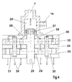
- FIG. 5 an embodiment of a spinning beam is shown, as in of the spinning system from FIG. 1 or FIG. 3 can be used.
- the spinning beam has a spinning station with the two spinnerets 9.
- the spinnerets 9 are through the melt manifolds 15 with the manifold pump 11 connected.
- the distributor pump 11 has a driven sun gear 29 and the planet gears 30 and 31.
- Concentric to the drive shaft 28 of the pump 11 is the inlet chamber 35 of the mixer 10 educated.
- the mixing devices 43 are inside the drive shaft 28 the inlet chamber 35 is arranged.
- the drive shaft 28 ends outside of Spin beam and is coupled to the motor 42.
- the inlet chamber 35 is connected to the melt line 7.
- Between the distributor pump 11 and the mixer 10 has two melt channels 44.1 and 44.2.
- the Feed line 14.2 connects the mixer 10 to a feed pump 45.
- the feed pump is arranged within the housing plate 33. Aligned an extruder screw 40 is arranged to the pump wheel 41. The extruder screw 40 and the impeller 41 are connected to each other.
- the extruder screw 40 is in the extruder barrel 13 of the secondary extruder 2 let in.
- the extruder cylinder 13 is connected to the filling device 6.
- the filling device 6 has a metering device 54.
- the extruder screw ends outside the spinning beam and is with the motor 5 coupled.
- the spinning beam 8 is heated, for example, diphyl.
- the main melt stream passes through the feed line 7 in the inlet chamber 35 of the mixer 11.
- Additive metered in via the filling device 6 through the secondary extruder 2 melted and homogenized. Then this generated one arrives Secondary flow via the feed channel 14.1 to the feed pump 45
- the feed pump then conveys the secondary flow via the feed line 14.2 to the inlet chamber 35 of the mixer 10.
- Im Mixer 10 is the mixing of the main melt stream with the Sidestream.
- the distributor pump acts as a double single pump, each with one of the two Spinnerets 9 is connected by the melt distribution line 15.
- Another way to influence the filling level of the feed pump consists of the pump pre-pressure as a signal for the metering setting in the filling device to use.
- the secondary extruder has one variable fill level.
- the feed device is by a pump 25 formed, which is connected to a feed channel 48 via the filling device 6 is.
- the feed channel 48 and the pump 25 are within the Spinning beam 8 arranged.
- the pump 25 is a gear pump with the Pump wheels 41 and 49 formed.
- the impeller 41 is on the Drive shaft 50 and the motor 5 driven. The sidestream generated with it is fed to the mixer 10 via the feed line 14.
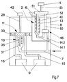
- FIG. 7 shows a further exemplary embodiment of a spinning beam, as can be used, for example, in the spinning system from FIG. 1 or 3.
- the mixer 10 is on the side of the distributor pump 11 facing away from the drive arranged.
- the drive shaft 28 by the outside of the spinning beam 8 arranged motor 42 is driven so that the opposite end of the pump drive shaft as a mixer shaft 37 is executed and protrudes into the mixing chamber 35.
- the feed line 14.2 connects the Feed pump 45 with the melt line 7, so that the bypass and Main flow together through an inlet opening in the mixer chamber 35 enter.
- the feed pump 45 is connected via the feed line 14.1 to the Auxiliary extruder 2 connected.
- the feed pump and the auxiliary extruder are arranged such that the drive shaft 50 of the feed pump 45 and the Shaft 52 of the extruder screw 40 together with a gear 51 are driven.
- the gear 51 is connected via a drive shaft 53 connected to the engine 5.
- the feed device is according to the embodiment Fig. 7 also with the mixer arrangement from the embodiment Fig. 5 can be combined.
- the required thermal energy is e.g. for plasticizing a color masterbatch gained from heating the spinning beam.
- an additional heater especially heating tapes, for the Use extruder.
Landscapes
- Engineering & Computer Science (AREA)
- Mechanical Engineering (AREA)
- Textile Engineering (AREA)
- Spinning Methods And Devices For Manufacturing Artificial Fibers (AREA)
Applications Claiming Priority (2)
| Application Number | Priority Date | Filing Date | Title |
|---|---|---|---|
| DE19643351 | 1996-10-21 | ||
| DE19643351 | 1996-10-21 |
Publications (3)
| Publication Number | Publication Date |
|---|---|
| EP0837161A2 true EP0837161A2 (fr) | 1998-04-22 |
| EP0837161A3 EP0837161A3 (fr) | 1998-12-23 |
| EP0837161B1 EP0837161B1 (fr) | 2002-09-04 |
Family
ID=7809311
Family Applications (1)
| Application Number | Title | Priority Date | Filing Date |
|---|---|---|---|
| EP97118082A Expired - Lifetime EP0837161B1 (fr) | 1996-10-21 | 1997-10-17 | Procédé et dispositif pour le filage de filaments thermoplastiques |
Country Status (3)
| Country | Link |
|---|---|
| US (1) | US5902531A (fr) |
| EP (1) | EP0837161B1 (fr) |
| DE (1) | DE59708113D1 (fr) |
Cited By (4)
| Publication number | Priority date | Publication date | Assignee | Title |
|---|---|---|---|---|
| DE10233468A1 (de) * | 2002-07-24 | 2004-02-12 | Barmag Ag | Vorrichtung und Verfahren zum Einspeisen einer flüssigen Farbe in eine Polymerschmelze |
| CN103556242A (zh) * | 2013-11-14 | 2014-02-05 | 苏州千色纺化纤有限公司 | 一种用于生产由聚酯纤维制成的纺织线的加工装置 |
| CN103603062A (zh) * | 2013-11-14 | 2014-02-26 | 苏州千色纺化纤有限公司 | 一种有彩色纺织线的加工装置 |
| DE102015001392A1 (de) | 2015-02-04 | 2016-08-04 | Bb Engineering Gmbh | Verfahren und Vorrichtung zum Einspeisen eines Zusatzstoffes in einen Schmelzstrom einer Polymerschmelze |
Families Citing this family (14)
| Publication number | Priority date | Publication date | Assignee | Title |
|---|---|---|---|---|
| DE19924838A1 (de) * | 1999-05-29 | 2000-11-30 | Lurgi Zimmer Ag | Spinnvorrichtung zum Verspinnen schmelzflüssiger Polymere und Verfahren zum Beheizen der Spinnvorrichtung |
| US6846450B2 (en) * | 2002-06-20 | 2005-01-25 | 3M Innovative Properties Company | Method for making a nonwoven web |
| US6824733B2 (en) * | 2002-06-20 | 2004-11-30 | 3M Innovative Properties Company | Meltblowing apparatus employing planetary gear metering pump |
| DE10235936A1 (de) * | 2002-08-06 | 2004-02-19 | Barmag Ag | Vorrichtung zum Spinnen und Aufwickeln |
| CN1745201A (zh) * | 2003-01-29 | 2006-03-08 | 苏拉有限及两合公司 | 用来纺造有色纤维的装置和方法 |
| DE102008038328A1 (de) | 2007-09-27 | 2009-04-02 | Oerlikon Textile Gmbh & Co. Kg | Verfahren und Vorrichtung zum Schmelzspinnen einer Mehrzahl einfarbiger Filamente |
| DE102009038661A1 (de) | 2008-09-05 | 2010-04-29 | Oerlikon Textile Gmbh & Co. Kg | Schmelzspinnvorrichtung |
| CN102134756B (zh) * | 2011-03-23 | 2012-11-21 | 江苏华西村股份有限公司 | 荧光增白涤纶短纤产品均一性的控制方法 |
| CN103556243A (zh) * | 2013-11-14 | 2014-02-05 | 苏州千色纺化纤有限公司 | 用于生产由聚酯纤维制成的纺织线的加工装置 |
| CN107201555B (zh) * | 2017-07-12 | 2022-09-06 | 苏州龙杰特种纤维股份有限公司 | 一种母粒加入系统以及制备有色纤维的方法 |
| EP3666939A1 (fr) * | 2018-12-12 | 2020-06-17 | Aladdin Manufactuing Corporation | Ensemble multifilament de filaments de polymeres fusionnes |
| CN110629298A (zh) * | 2019-11-06 | 2019-12-31 | 韶关学院 | 一种熔体静电纺丝装置及其方法 |
| CN114427123B (zh) * | 2022-01-27 | 2023-04-25 | 九江中科鑫星新材料有限公司 | 一种超高分子量聚乙烯纤维生产用保温机构 |
| CN115595695A (zh) * | 2022-11-10 | 2023-01-13 | 富尔美技术纺织(苏州)有限公司(Cn) | 一种高均匀性防紫外环锭纺纱线的加工工艺 |
Citations (9)
| Publication number | Priority date | Publication date | Assignee | Title |
|---|---|---|---|---|
| DE2430533A1 (de) * | 1973-06-26 | 1975-01-23 | Toray Industries | Polyesterfaeden und verfahren zu deren herstellung |
| JPS56134208A (en) * | 1980-03-21 | 1981-10-20 | Unitika Ltd | Spinneret apparatus for multicomponent blend spinning |
| JPS58126311A (ja) * | 1982-01-18 | 1983-07-27 | Nippon Ester Co Ltd | 混練紡糸パツク |
| JPS60119211A (ja) * | 1983-11-25 | 1985-06-26 | Teijin Ltd | 溶融混合紡糸装置 |
| JPS6147808A (ja) * | 1984-08-10 | 1986-03-08 | Nippon Ester Co Ltd | 混合紡糸用口金パツク |
| JPS61174412A (ja) * | 1985-01-23 | 1986-08-06 | Nippon Ester Co Ltd | 混合紡糸用口金パツク |
| US4617235A (en) * | 1983-05-23 | 1986-10-14 | Unitika Ltd. | Antistatic synthetic fibers |
| JPH06101110A (ja) * | 1992-09-14 | 1994-04-12 | Mitsubishi Rayon Co Ltd | 多錘溶融混合高速紡糸方法 |
| WO1996014450A1 (fr) * | 1994-11-08 | 1996-05-17 | Hills, Inc. | Procede de fabrication d'une fibre contenant un additif |
Family Cites Families (2)
| Publication number | Priority date | Publication date | Assignee | Title |
|---|---|---|---|---|
| US3881850A (en) * | 1974-01-02 | 1975-05-06 | Eastman Kodak Co | Melt spinning tower module and circular melt spin block therefor |
| US5637331A (en) * | 1993-02-18 | 1997-06-10 | Barmag Ag | Spin system for thermoplastic yarns |
-
1997
- 1997-10-17 EP EP97118082A patent/EP0837161B1/fr not_active Expired - Lifetime
- 1997-10-17 DE DE59708113T patent/DE59708113D1/de not_active Expired - Fee Related
- 1997-10-21 US US08/954,812 patent/US5902531A/en not_active Expired - Fee Related
Patent Citations (9)
| Publication number | Priority date | Publication date | Assignee | Title |
|---|---|---|---|---|
| DE2430533A1 (de) * | 1973-06-26 | 1975-01-23 | Toray Industries | Polyesterfaeden und verfahren zu deren herstellung |
| JPS56134208A (en) * | 1980-03-21 | 1981-10-20 | Unitika Ltd | Spinneret apparatus for multicomponent blend spinning |
| JPS58126311A (ja) * | 1982-01-18 | 1983-07-27 | Nippon Ester Co Ltd | 混練紡糸パツク |
| US4617235A (en) * | 1983-05-23 | 1986-10-14 | Unitika Ltd. | Antistatic synthetic fibers |
| JPS60119211A (ja) * | 1983-11-25 | 1985-06-26 | Teijin Ltd | 溶融混合紡糸装置 |
| JPS6147808A (ja) * | 1984-08-10 | 1986-03-08 | Nippon Ester Co Ltd | 混合紡糸用口金パツク |
| JPS61174412A (ja) * | 1985-01-23 | 1986-08-06 | Nippon Ester Co Ltd | 混合紡糸用口金パツク |
| JPH06101110A (ja) * | 1992-09-14 | 1994-04-12 | Mitsubishi Rayon Co Ltd | 多錘溶融混合高速紡糸方法 |
| WO1996014450A1 (fr) * | 1994-11-08 | 1996-05-17 | Hills, Inc. | Procede de fabrication d'une fibre contenant un additif |
Non-Patent Citations (6)
| Title |
|---|
| PATENT ABSTRACTS OF JAPAN vol. 006, no. 011 (C-088), 22. Januar 1982 & JP 56 134208 A (UNITIKA LTD), 20. Oktober 1981 * |
| PATENT ABSTRACTS OF JAPAN vol. 007, no. 235 (C-191), 19. Oktober 1983 & JP 58 126311 A (NIPPON ESTER KK), 27. Juli 1983 * |
| PATENT ABSTRACTS OF JAPAN vol. 009, no. 271 (C-311), 29. Oktober 1985 & JP 60 119211 A (TEIJIN KK), 26. Juni 1985 * |
| PATENT ABSTRACTS OF JAPAN vol. 010, no. 208 (C-361), 22. Juli 1986 & JP 61 047808 A (NIPPON ESTER CO LTD), 8. März 1986 * |
| PATENT ABSTRACTS OF JAPAN vol. 010, no. 383 (C-393), 23. Dezember 1986 & JP 61 174412 A (NIPPON ESTER CO LTD), 6. August 1986 * |
| PATENT ABSTRACTS OF JAPAN vol. 018, no. 377 (C-1225), 15. Juli 1994 & JP 06 101110 A (MITSUBISHI RAYON CO LTD), 12. April 1994 * |
Cited By (4)
| Publication number | Priority date | Publication date | Assignee | Title |
|---|---|---|---|---|
| DE10233468A1 (de) * | 2002-07-24 | 2004-02-12 | Barmag Ag | Vorrichtung und Verfahren zum Einspeisen einer flüssigen Farbe in eine Polymerschmelze |
| CN103556242A (zh) * | 2013-11-14 | 2014-02-05 | 苏州千色纺化纤有限公司 | 一种用于生产由聚酯纤维制成的纺织线的加工装置 |
| CN103603062A (zh) * | 2013-11-14 | 2014-02-26 | 苏州千色纺化纤有限公司 | 一种有彩色纺织线的加工装置 |
| DE102015001392A1 (de) | 2015-02-04 | 2016-08-04 | Bb Engineering Gmbh | Verfahren und Vorrichtung zum Einspeisen eines Zusatzstoffes in einen Schmelzstrom einer Polymerschmelze |
Also Published As
| Publication number | Publication date |
|---|---|
| US5902531A (en) | 1999-05-11 |
| DE59708113D1 (de) | 2002-10-10 |
| EP0837161B1 (fr) | 2002-09-04 |
| EP0837161A3 (fr) | 1998-12-23 |
Similar Documents
| Publication | Publication Date | Title |
|---|---|---|
| EP0837161B1 (fr) | Procédé et dispositif pour le filage de filaments thermoplastiques | |
| DE2214571C3 (de) | Vorrichtung zum Tränken und Überziehen von fadenförmigem Material mit einem fließfähigen polymeren Harz | |
| EP2558626B1 (fr) | Dispositif pour enlever et enrouler des fils synthétiques | |
| EP2203578B1 (fr) | Procédé et dispositif pour la fabrication d'un filament composite polychrome | |
| EP1587972A1 (fr) | Dispositif et procede pour filer des fibres colorees | |
| DE102009038496A1 (de) | Vorrichtung zum Schmelzspinnen und Aufwickeln mehrerer synthetischer Fäden | |
| EP0636190B1 (fr) | Installation de filage de fils thermoplastiques | |
| WO2002028520A1 (fr) | Dispositif pour premelanger des additifs et les introduire dans un flux de polymere en fusion | |
| WO2012113668A1 (fr) | Dispositif de filage par fusion | |
| EP1735484B1 (fr) | Procede et dispositif de filage a chaud de plusieurs fils multibrins | |
| DE202007004997U1 (de) | Extrudervorrichtung | |
| DE102008023807A1 (de) | Vorrichtung zum Schmelzspinnen einer Mehrzahl von Verbundfäden | |
| DE202007005010U1 (de) | Vorrichtung, insbesondere Imprägniervorrichtung | |
| EP0035974B1 (fr) | Dispositif pour fabriquer un granulé en matière plastique, remforcé de fibres de verre | |
| DE102011011790A1 (de) | Vorrichtung zum Extrudieren und Abkühlen einer Vielzahl von Monofilamenten | |
| DE19956251A1 (de) | Einrichtung zum Herstellen künstlicher Filamente | |
| DE4305905C1 (de) | Spinnpumpe mit Mischer | |
| DE102006053718A1 (de) | Verfahren und Vorrichtung zum Schmelzspinnen, Abkühlen und Präparieren eines mutifilen Fadens | |
| DE102014015729A1 (de) | Vorrichtung und Verfahren zum Schmelzspinnen und Kühlen einer Filamentschar | |
| DE102012017825A1 (de) | Verfahren und Vorrichtung zum Schmelzspinnen mehrerer multifiler Fäden | |
| DE102007016346A1 (de) | Mehrwellenextrudervorrichtung und Verfahren zum Betreiben derselben | |
| DE3210666A1 (de) | Fluidstrahlorgan, insbesondere fluidduese, zur herstellung texturierter bzw. strukturierter faeden | |
| DE102008038328A1 (de) | Verfahren und Vorrichtung zum Schmelzspinnen einer Mehrzahl einfarbiger Filamente | |
| EP1467005A1 (fr) | Procédé et dispositif pour le filage au fondu et refroidissement d'un faisceau de filaments | |
| DE102007016352A1 (de) | Mehrwellenextrudervorrichtung und Verfahren zum Betreiben derselben |
Legal Events
| Date | Code | Title | Description |
|---|---|---|---|
| PUAI | Public reference made under article 153(3) epc to a published international application that has entered the european phase |
Free format text: ORIGINAL CODE: 0009012 |
|
| AK | Designated contracting states |
Kind code of ref document: A2 Designated state(s): CH DE FR GB IT LI |
|
| AX | Request for extension of the european patent |
Free format text: AL;LT;LV;RO;SI |
|
| PUAL | Search report despatched |
Free format text: ORIGINAL CODE: 0009013 |
|
| AK | Designated contracting states |
Kind code of ref document: A3 Designated state(s): AT BE CH DE DK ES FI FR GB GR IE IT LI LU MC NL PT SE |
|
| AX | Request for extension of the european patent |
Free format text: AL;LT;LV;RO;SI |
|
| 17P | Request for examination filed |
Effective date: 19990225 |
|
| AKX | Designation fees paid |
Free format text: CH DE FR GB IT LI |
|
| 17Q | First examination report despatched |
Effective date: 20010119 |
|
| GRAG | Despatch of communication of intention to grant |
Free format text: ORIGINAL CODE: EPIDOS AGRA |
|
| GRAG | Despatch of communication of intention to grant |
Free format text: ORIGINAL CODE: EPIDOS AGRA |
|
| GRAH | Despatch of communication of intention to grant a patent |
Free format text: ORIGINAL CODE: EPIDOS IGRA |
|
| GRAH | Despatch of communication of intention to grant a patent |
Free format text: ORIGINAL CODE: EPIDOS IGRA |
|
| GRAA | (expected) grant |
Free format text: ORIGINAL CODE: 0009210 |
|
| AK | Designated contracting states |
Kind code of ref document: B1 Designated state(s): CH DE FR GB IT LI |
|
| REG | Reference to a national code |
Ref country code: GB Ref legal event code: FG4D Free format text: NOT ENGLISH |
|
| REG | Reference to a national code |
Ref country code: CH Ref legal event code: EP |
|
| REF | Corresponds to: |
Ref document number: 59708113 Country of ref document: DE Date of ref document: 20021010 |
|
| REG | Reference to a national code |
Ref country code: CH Ref legal event code: NV Representative=s name: HERMANN KAHLHOEFER |
|
| GBT | Gb: translation of ep patent filed (gb section 77(6)(a)/1977) |
Effective date: 20021217 |
|
| ET | Fr: translation filed | ||
| PLBE | No opposition filed within time limit |
Free format text: ORIGINAL CODE: 0009261 |
|
| STAA | Information on the status of an ep patent application or granted ep patent |
Free format text: STATUS: NO OPPOSITION FILED WITHIN TIME LIMIT |
|
| 26N | No opposition filed |
Effective date: 20030605 |
|
| PGFP | Annual fee paid to national office [announced via postgrant information from national office to epo] |
Ref country code: DE Payment date: 20081103 Year of fee payment: 12 Ref country code: CH Payment date: 20081027 Year of fee payment: 12 |
|
| PGFP | Annual fee paid to national office [announced via postgrant information from national office to epo] |
Ref country code: IT Payment date: 20081022 Year of fee payment: 12 |
|
| PGFP | Annual fee paid to national office [announced via postgrant information from national office to epo] |
Ref country code: FR Payment date: 20081024 Year of fee payment: 12 |
|
| PGFP | Annual fee paid to national office [announced via postgrant information from national office to epo] |
Ref country code: GB Payment date: 20081028 Year of fee payment: 12 |
|
| REG | Reference to a national code |
Ref country code: CH Ref legal event code: PL |
|
| REG | Reference to a national code |
Ref country code: FR Ref legal event code: ST Effective date: 20100630 |
|
| PG25 | Lapsed in a contracting state [announced via postgrant information from national office to epo] |
Ref country code: FR Free format text: LAPSE BECAUSE OF NON-PAYMENT OF DUE FEES Effective date: 20091102 Ref country code: DE Free format text: LAPSE BECAUSE OF NON-PAYMENT OF DUE FEES Effective date: 20100501 |
|
| PG25 | Lapsed in a contracting state [announced via postgrant information from national office to epo] |
Ref country code: LI Free format text: LAPSE BECAUSE OF NON-PAYMENT OF DUE FEES Effective date: 20091031 Ref country code: CH Free format text: LAPSE BECAUSE OF NON-PAYMENT OF DUE FEES Effective date: 20091031 |
|
| PG25 | Lapsed in a contracting state [announced via postgrant information from national office to epo] |
Ref country code: GB Free format text: LAPSE BECAUSE OF NON-PAYMENT OF DUE FEES Effective date: 20091017 |
|
| PG25 | Lapsed in a contracting state [announced via postgrant information from national office to epo] |
Ref country code: IT Free format text: LAPSE BECAUSE OF NON-PAYMENT OF DUE FEES Effective date: 20091017 |