EP0836088A2 - Verfahren und Einrichtung zum Prüfen der Dichtigkeit von Fugen an Betonbauwerken - Google Patents
Verfahren und Einrichtung zum Prüfen der Dichtigkeit von Fugen an Betonbauwerken Download PDFInfo
- Publication number
- EP0836088A2 EP0836088A2 EP97117600A EP97117600A EP0836088A2 EP 0836088 A2 EP0836088 A2 EP 0836088A2 EP 97117600 A EP97117600 A EP 97117600A EP 97117600 A EP97117600 A EP 97117600A EP 0836088 A2 EP0836088 A2 EP 0836088A2
- Authority
- EP
- European Patent Office
- Prior art keywords
- sealing material
- joint
- measuring chamber
- test gas
- joints
- Prior art date
- Legal status (The legal status is an assumption and is not a legal conclusion. Google has not performed a legal analysis and makes no representation as to the accuracy of the status listed.)
- Withdrawn
Links
Images
Classifications
-
- G—PHYSICS
- G01—MEASURING; TESTING
- G01M—TESTING STATIC OR DYNAMIC BALANCE OF MACHINES OR STRUCTURES; TESTING OF STRUCTURES OR APPARATUS, NOT OTHERWISE PROVIDED FOR
- G01M3/00—Investigating fluid-tightness of structures
- G01M3/02—Investigating fluid-tightness of structures by using fluid or vacuum
- G01M3/04—Investigating fluid-tightness of structures by using fluid or vacuum by detecting the presence of fluid at the leakage point
- G01M3/20—Investigating fluid-tightness of structures by using fluid or vacuum by detecting the presence of fluid at the leakage point using special tracer materials, e.g. dye, fluorescent material, radioactive material
- G01M3/22—Investigating fluid-tightness of structures by using fluid or vacuum by detecting the presence of fluid at the leakage point using special tracer materials, e.g. dye, fluorescent material, radioactive material for pipes, cables or tubes; for pipe joints or seals; for valves; for welds; for containers, e.g. radiators
- G01M3/223—Investigating fluid-tightness of structures by using fluid or vacuum by detecting the presence of fluid at the leakage point using special tracer materials, e.g. dye, fluorescent material, radioactive material for pipes, cables or tubes; for pipe joints or seals; for valves; for welds; for containers, e.g. radiators for pipe joints or seals
Definitions
- the present invention relates to a method and a device for testing or monitoring or Age tracking of the tightness of joints on structures, like buildings, bridges, pools and the like after the The preamble of claim 1 or 6 or that of claim 6 or 14.
- the object of the present invention is therefore a Method and device for testing or monitoring or for tracking the age of the tightness of joints on buildings of the type mentioned at the beginning to provide for renovation a joint seal or before renovating one again already renovated joint sealing a decision on the To be able to meet the need for renovation.
- the measurement takes place on this Measuring chamber side instead.
- a time interval can be almost constant permeability of the sealing material can be determined, which a new condition of the examined Sealing material corresponds.
- the condition as good as new is, in particular, not yet the Embrittlement or permeability Removal of material noticeable, micro cracks and a decrease in Compression forces of the sealing material are also (still) cannot be determined, nor are there yet Detachment phenomena of the sealing material to the adjacent one Seal seat recognizable. So there will be information about one to be examined sealing material or a sealing element long from a macroscopic leak. Consequently there is the possibility to go through in a long-term trial continuous measurement or measurement at intervals to track the duration of this new condition measure up.
- claims 2 and 10 are preferred provided to take measurements from time to time take place to get clear analysis results.
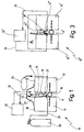
- the device 10 or 2 shown in FIGS. 10 ' is used for discontinuous checking of the tightness a component joint 11 between two concrete slabs 12 and 13 a concrete structure, such as a building, a bridge, one Basin in, for example, wastewater treatment plants and the like. If the two concrete slabs 12 and 13 here are shown arranged side by side, it is understood that the joint can also be in a corner area or the like can.
- the joint 11 is with a commercially available sealing material 14 filled in an area that the outer or surface 16, 17 of the two concrete slabs 12, 13 faces.
- the device 10 shown in Figure 1 has one perforated tube 21, which is below the sealing material 14 arranged in the joint 11 and in a manner not shown is held.
- the perforated tube 21 is already at Making the joint seal has been introduced.
- the perforated tube 21 runs preferably over the entire length of the joint 11 and is on accessible at both ends in a manner not shown.
- a Measuring chamber 22 Over the joint 11 provided with the sealing material 14 is a Measuring chamber 22 arranged, the building side of the joint 11th or their sealing material 14 and the adjacent areas of the Surface 16, 17 of the concrete slab 12, 13 and the top of one channel-like hood 23 is limited.
- the hood 23 runs over the entire length or at least over that section of the Joint 11, which is to be checked for leaks.
- the channel-like hood 23 is not shown in Figure 1 in Sealing on the surface 16, 17 of the concrete slab
- the perforated Tube 21 with one end via a line 27 with connected to a test gas source in the form of a test gas bottle 26.
- the other end of the perforated tube 21 can either be closed or, as shown in Figure 1, over a pipe 28 is connected to an airbag 29.
- the Measuring chamber 22 is via a line 31 or in closed-loop operation over two lines with one Test gas analyzer 32 connected.
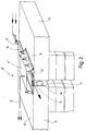
- FIG. 2 shows a representation in which the device 10 ' to check the tightness of a parting line at a already renovated joint 11 is used.
- the embodiment of Figure 1 is that between concrete slabs 12, 13 existing joint 11 with a sealing material 14 filled out. Since this sealing material 14 was already leaking, the joint 11 was e.g. redeveloped by that about them a flat sealing material in the form of a bridge elastic sealing tape 15 was placed on the adjacent areas 16, 17 of the concrete slabs 12, 13 through Glue or the like is attached. When renovating was on the sealing material 14 but under the sealing tape 15 perforated tube 21 'over the corresponding length of the Fugue 11 inserted.
- a measuring chamber 22 ' is also here provided that covered by a channel-like hood 23 ' is, as described for Figure 1, over the relevant Section of the joint 11 on the edge and end sealing the concrete slabs 12, 13 is brought.
- the perforated tube 21 ' is first flushed out with the aid of a carrier gas, for example N 2 , coming from a source which is not shown.
- a carrier gas for example N 2
- the measuring chamber 22 ' which is also initially supplied with a purge gas or carrier gas. Only then is the checking and measuring method described in FIG. 1 carried out using the test gas coming from a test gas source (not shown).
- the carrier gas and test gas are introduced almost without pressure, ie with a pressure of less than 0.1 bar.
- FIG. 3 shows a representation corresponding to FIG Joint 11 '' between two concrete slabs 12 '' and 13 '', the Groove through sealing material 14 '' in the corresponding, above described area is filled.
- the device 10 ′′ has a perforated tube 21 ′′, that in this embodiment for continuous Monitor the tightness of the joint 11 at both ends with the entrance or the entrance and exit of the Gas analysis device 32 '' connected via lines 33, 34 is.
- quantitative and / or qualitatively monitored whether from the free (e.g. gases) or filled (e.g. waste water) room 36 above the concrete slabs 12, 13 or the joint 11 by permeation gas through the Sealing material 14 '' penetrates and into the perforated tube 21 '' reached.
- Purified air becomes from the perforated tube 21 or another introduced carrier gas into the Gas analyzer 32 '' brought in the air or the Carrier gas possibly contained from room 36 diffused gas is measured and analyzed.
- the joints described at the beginning are not just about Component joints but also connection joints, parting lines, Maintenance joints and the like act.
- the one with the joints Underground can be a concrete, ceramic, sealed Surface or the like have.
- a time axis indicates the start time at the Implementation of the method according to the invention; it will usually act at the time when the test side of the sealing material with the test medium for the first time is applied. It then becomes continuous or in time intervals the concentration of the permeant (Test gas) on the from the test side of the sealing material facing away from the measuring chamber side. The concentration will increase in the first phase and increase in the second phase stabilize to a substantially constant value. It there is the possibility of going through the puncture Determine extrapolation of the measured values.
- a time t2 marks the transition from a first to a second phase in which the concentration on the measuring chamber side is essentially constant or with constant rate increases slightly. Is in this second phase the permeability of the sealing material for the permeant constant. The sealing material is in his Mint condition. There is no risk that Macroscopically noticeable leaks occur.
- This second Phase can change when long-term measurements are carried out and operational-like conditions are simulated, i.e. not by extreme boundary conditions a premature aging of a Sealing material is brought about over a very long time, possibly spanning years.
- This third phase is the increasing permeability characterized in that the sealing material is still is useful - no macroscopic yet noticeable leaks - the tightness reserves of the However, the sealing material is reduced by the Sealing structure is increasingly disturbed and smaller cracks shows, however, as a result of sufficient compression are sufficiently pressure-tight within the sealing material.
Landscapes
- Physics & Mathematics (AREA)
- General Physics & Mathematics (AREA)
- Examining Or Testing Airtightness (AREA)
- Bridges Or Land Bridges (AREA)
Abstract
Description
- Figur 1
- in schematischer Ansicht eine Einrichtung zum diskontinuierlichen Überprüfen der Dichtigkeit einer Bauteilfuge an einem Betonbauwerk gemäß einem ersten Ausführungsbeispiel vorliegender Erfindung;
- Figur 2
- in schematischer perspektivischer Darstellung eine Einrichtung ähnlich der der Figur 1, jedoch zum überprüfen der Dichtigkeit einer bereits sanierten Trennfuge an einem Betonbauwerk gemäß einem anderen Ausführungsbeispiel vorliegender Erfindung und
- Figur 3
- in schematischer Ansicht eine Einrichtung zum kontinuierlichen Überwachen der Dichtigkeit einer Bauteilfuge an einem Betonbauwerk gemäß einem weiteren Ausführungsbeispiel vorliegender Erfindung.
Claims (14)
- Verfahren zum Prüfen bzw. Überwachen bzw. zur Alterungsverfolgung der Dichtigkeit von Fugen an Bauwerken, wie Gebäude, Brücken, Becken und dergleichen, welche Fugen im Bereich der Bauwerksaußen- bzw. - oberfläche mit einem ersten Dichtmaterial ausgefüllt oder mit einem die Fuge und das erste Dichtmaterial überbrückenden zweiten Dichtmaterial saniert sind, dadurch gekennzeichnet, dass die unterhalb des ersten oder zweiten Dichtmaterials mit einem perforierten Röhrchen versehene Fuge längs ihres zu prüfenden bzw. zu überwachenden Abschnitts von einer Messkammer überdeckt wird, dass durch das perforierte Röhrchen ein Prüfgas nahezu drucklos geführt und dass in der zur Fuge hin offenen Messkammer eine Prüfgas-Permeationsanalyse durchgeführt wird.
- Verfahren nach Anspruch 1, dadurch gekennzeichnet, dass vor dem Zuführen von Prüfgas das perforierte Röhrchen und/oder die Messkammer mit einem Trägergas gespült wird.
- Verfahren nach Anspruch 1 oder 2, dadurch gekennzeichnet, dass das Trägergas und/oder das Prüfgas bei einem geringen Druck von kleiner 0,1 bar in das Röhrchen eingebracht wird.
- Verfahren nach mindestens einem der vorhergehenden Ansprüche, dadurch gekennzeichnet, dass nach dem Einbringen des Prüfgases in das perforierte Röhrchen vor dem Durchführen der Analyse eine Beruhigungszeit von einigen Minuten abgewartet wird.
- Verfahren nach mindestens einem der vorhergehenden Ansprüche, dadurch gekennzeichnet, das das Verfahren diskontinuierlich durchgeführt wird.
- Verfahren zum Prüfen bzw. Überwachen bzw. zur Alterungsverfolgung der Dichtigkeit von Fugen an Bauwerken, wie Gebäude, Brücken, Becken und dergleichen, welche Fugen im Bereich der Bauwerksaußen- bzw. oberfläche mit einem ersten Dichtmaterial ausgefüllt oder mit einem die Fuge und das erste Dichtmaterial überbrückenden zweiten Dichtmaterial saniert sind, dadurch gekennzeichnet, dass ein unterhalb des ersten oder zweiten Dichtmaterials verlaufendes perforiertes Röhrchen längs des zu prüfenden bzw. zu überwachenden Abschnitts als Messkammer verwendet wird, in der eine Prüfgaspermeationsanalyse durchgeführt wird.
- Verfahren nach Anspruch 6, dadurch gekennzeichnet, dass das Verfahren kontinuierlich durchgeführt wird.
- Einrichtung zum Prüfen bzw. Überwachen bzw. der Alterungsverfolgung der Dichtigkeit von Fugen an Bauwerken, wie Gebäude, Brücken, Becken und dergleichen, welche Fugen im Bereich der Bauwerksaußen- bzw. - oberfläche mit einem ersten Dichtmaterial ausgefüllt oder mit einem die Fuge und das erste Dichtmaterial überbrückenden zweiten Dichtmaterial saniert sind, gekennzeichnet durch ein unterhalb des ersten oder des zweiten Dichtmaterials (14, 15) längs zumindest eines Teils des Fugenverlaufs verlegtes perforiertes Röhrchen (21), durch eine über den zu prüfenden bzw. zu überwachenden Fugenbereich (11) an der Bauwerksaußen- bzw. -oberfläche (16, 17) angeordnete und mit dem Fugenbereich (11) in Verbindung stehende Messkammer (22) und durch eine Messanordnung aus einer mit dem Röhrchen (21) verbundenen Prüfgasquelle (26) und einer mit der Messkammer (22) verbundenen Prüfgasanalysevorrichtung (32).
- Vorrichtung nach Anspruch 8, dadurch gekennzeichnet, dass die Messkammer von einer kanalartig profilierten Haube (23) gebildet ist, die auf die Bauwerksaußen- bzw. - oberfläche im Fugenbereich (11) dichtend aufgelegt ist.
- Einrichtung nach Anspruch 8 oder 9, dadurch gekennzeichnet, dass eine Spülgasquelle vorgesehen ist.
- Einrichtung nach mindestens einem der Ansprüche 8 bis 10, dadurch gekennzeichnet, dass das eine Ende des perforierten Röhrchens (21) mit der Prüfgas- und/oder Spülgasquelle verbindbar ist.
- Einrichtung nach mindestens einem der Ansprüche 8 bis 11, dadurch gekennzeichnet, dass das andere Ende des perforierten Röhrchens (21) mit einem Gassack (29) verbindbar ist.
- Einrichtung nach mindestens einem der Ansprüche 8 bis 12, dadurch gekennzeichnet, dass das Prüfgas unter einem geringen Druck von kleiner 0,1 bar ansteht.
- Einrichtung zum Prüfen bzw. Überwachen bzw. der Alterungsverfolgung der Dichtigkeit von Fugen an Bauwerken, wie Gebäude, Brücken, Becken und dergleichen, welche Fugen im Bereich der Bauwerksaußen- bzw. oberfläche mit einem ersten Dichtmaterial ausgefüllt oder mit einem die Fuge und das erste Dichtmaterial überbrückenden zweiten Dichtmaterial saniert sind, gekennzeichnet durch ein unterhalb des ersten oder des zweiten Dichtmaterials (14, 15) längs zumindest eines Teils des Fugenverlaufs verlegtes perforiertes Röhrchen (21), mit dem Fugenbereich (11) in Verbindung stehende Messkammer (22) und durch eine Messanordnung aus einer durch das Röhrchen (21) gebildeten Messkammer (22) und einer mit der Messkammer (22) verbundenen Prüfgasanalysevorrichtung (32).
Applications Claiming Priority (2)
| Application Number | Priority Date | Filing Date | Title |
|---|---|---|---|
| DE1996142136 DE19642136A1 (de) | 1996-10-12 | 1996-10-12 | Verfahren und Einrichtung zum Prüfen der Dichtigkeit von Fugen an Betonbauwerken |
| DE19642136 | 1996-10-12 |
Publications (2)
| Publication Number | Publication Date |
|---|---|
| EP0836088A2 true EP0836088A2 (de) | 1998-04-15 |
| EP0836088A3 EP0836088A3 (de) | 1999-01-20 |
Family
ID=7808574
Family Applications (1)
| Application Number | Title | Priority Date | Filing Date |
|---|---|---|---|
| EP97117600A Withdrawn EP0836088A3 (de) | 1996-10-12 | 1997-10-10 | Verfahren und Einrichtung zum Prüfen der Dichtigkeit von Fugen an Betonbauwerken |
Country Status (2)
| Country | Link |
|---|---|
| EP (1) | EP0836088A3 (de) |
| DE (1) | DE19642136A1 (de) |
Cited By (3)
| Publication number | Priority date | Publication date | Assignee | Title |
|---|---|---|---|---|
| EP1160558A3 (de) * | 2000-05-30 | 2004-01-02 | De Zeven Son B.V. | Verfahren zur Prüfung der Dichtigkeit einer Dichtung und diesem Zweck dienendes eindringendes Element |
| CN114150772A (zh) * | 2021-12-14 | 2022-03-08 | 徐向前 | 一种组合式建筑施工预制件构件 |
| CN115015083A (zh) * | 2022-06-17 | 2022-09-06 | 中交第二公路勘察设计研究院有限公司 | 盾构隧道管片接缝双道密封垫防水性能测试装置及方法 |
Families Citing this family (2)
| Publication number | Priority date | Publication date | Assignee | Title |
|---|---|---|---|---|
| DE102017004776A1 (de) | 2017-05-17 | 2018-11-22 | Wolfgang Böttcher | Verfahren zur Dichtheitsprüfung von Stahlbetonbehältern sowie Stahlbetonbehälter zur Durchführung des Verfahrens |
| DE202020102257U1 (de) | 2019-05-11 | 2020-06-19 | Ssi Ingenieurgesellschaft Mbh | Versuchsanordnung für ein Kompressionsdichtprofil |
Family Cites Families (11)
| Publication number | Priority date | Publication date | Assignee | Title |
|---|---|---|---|---|
| US2958532A (en) * | 1959-02-13 | 1960-11-01 | Erickson Tool Co | Double acting diaphragm chuck |
| US4601194A (en) * | 1983-01-18 | 1986-07-22 | Damco Testers, Inc. | Method and apparatus for leak testing of pipe |
| JPS59147233A (ja) * | 1983-02-10 | 1984-08-23 | Mitsubishi Heavy Ind Ltd | 漏洩欠陥検出方法およびそのための装置 |
| DE3904594A1 (de) * | 1989-02-16 | 1990-08-30 | Becker Annette | Verfahren zum herstellen einer abdichtung fuer ingenieurbauten und pruefen der dichtigkeit der abdichtung |
| DE4134489A1 (de) * | 1991-03-28 | 1992-10-01 | Weatherford Prod & Equip | Einrichtung zum pruefen der gasdichtigkeit von loesbaren hohlkoerperverbindungen |
| DE4137473A1 (de) * | 1991-11-14 | 1993-05-19 | Siemens Ag | Ueberwachbare einrichtung und verfahren zum ueberwachen einer einrichtung zum abdichten eines koerpers |
| DE4139565C2 (de) * | 1991-11-30 | 1995-04-27 | Ecology Engineering Consulting | Flüssigkeitsdichte Auskleidung von Kanalrohren |
| SE500852C2 (sv) * | 1992-01-29 | 1994-09-19 | Mataki Ab | Sätt och anordning för läckagetest av med tätskikt klädda yttertak eller bjälklag |
| FR2688307B1 (fr) * | 1992-03-04 | 1997-10-24 | Aerospatiale | Procede de detection et de quantification globale de fuites sur au moins une jonction d'une capacite. |
| DE4232803C2 (de) * | 1992-09-30 | 1995-07-06 | R & T Umwelt Gmbh | Verfahren zur Ermittlung von Undichtigkeiten in Wannen und Vorrichtung zur Durchführung des Verfahrens |
| DE19535276A1 (de) * | 1995-09-22 | 1997-03-27 | Schuette Reiner | Fahrbahn mit Leckageüberwachung |
-
1996
- 1996-10-12 DE DE1996142136 patent/DE19642136A1/de not_active Ceased
-
1997
- 1997-10-10 EP EP97117600A patent/EP0836088A3/de not_active Withdrawn
Cited By (4)
| Publication number | Priority date | Publication date | Assignee | Title |
|---|---|---|---|---|
| EP1160558A3 (de) * | 2000-05-30 | 2004-01-02 | De Zeven Son B.V. | Verfahren zur Prüfung der Dichtigkeit einer Dichtung und diesem Zweck dienendes eindringendes Element |
| CN114150772A (zh) * | 2021-12-14 | 2022-03-08 | 徐向前 | 一种组合式建筑施工预制件构件 |
| CN114150772B (zh) * | 2021-12-14 | 2024-01-12 | 广东立宸建筑工程有限公司 | 一种组合式建筑施工预制件构件 |
| CN115015083A (zh) * | 2022-06-17 | 2022-09-06 | 中交第二公路勘察设计研究院有限公司 | 盾构隧道管片接缝双道密封垫防水性能测试装置及方法 |
Also Published As
| Publication number | Publication date |
|---|---|
| EP0836088A3 (de) | 1999-01-20 |
| DE19642136A1 (de) | 1998-04-16 |
Similar Documents
| Publication | Publication Date | Title |
|---|---|---|
| EP3534145B1 (de) | Fugenversuchsstand | |
| EP0836088A2 (de) | Verfahren und Einrichtung zum Prüfen der Dichtigkeit von Fugen an Betonbauwerken | |
| DE8902256U1 (de) | Prüfeinrichtung für eine Abdichtung für Ingenieurbauten | |
| DE3404073A1 (de) | Verfahren zum herstellen einer schlitzwand aus beton | |
| DE29521615U1 (de) | Rohrleitung für Abwasserleitungssysteme | |
| DE10131752A1 (de) | Anordnung und Verfahren zur Messung der Gasdurchlässigkeit eines porösen Baustoffes | |
| DD290040A5 (de) | Verfahren und vorrichtung zum sanieren von unbegehbaren kanalrohren | |
| DE69930682T2 (de) | Verfahren zur Prüfung der Dichtheit eines Bodens | |
| DE202020102257U1 (de) | Versuchsanordnung für ein Kompressionsdichtprofil | |
| DE4402862A1 (de) | Bauweise und Verfahren für die Druckprüfung von Talsperrendämmen mit Kerndichtung | |
| DE19641356C1 (de) | Verfahren und Vorrichtung zur Alterungsverfolgung von Dichtwerkstoffen | |
| DE29623935U1 (de) | Einrichtung zum Prüfen der Dichtigkeit von Fugen an Betonbauwerken | |
| DE102014016290A1 (de) | Dichtungsprüfung von Tunneln | |
| DE3586631T2 (de) | Verfahren zum lecknachweis in einem leitungssystem. | |
| EP0989405A1 (de) | Vorrichtung und Verfahren zur Analyse von chemischen Substratgehalten in einer Flüssigkeit | |
| DE3404354A1 (de) | Verfahren und vorrichtung zum abdichten von rohrleitungen | |
| DE102017123528B4 (de) | Verfahren zum Auffinden von Fehlstellen in Schlitzwänden oder zum Überprüfen der Dichtigkeit einer Schlitzwandfuge und thermisches Schlitzwandfugenkontrollsystem | |
| DE3842071C2 (de) | ||
| EP0915330A1 (de) | Verfahren und Vorrichtung zur Prüfung der Flüssigkeitsaufnahme poröser Baustoffe | |
| EP0684347B1 (de) | Verfahren zur Herstellung chemikalienbeständiger und flüssigkeitsundurchlässiger Dehnungsfugen | |
| DE69307193T2 (de) | Verfahren und Vorrichtung für die quantitative Bestimmung der Dichtigkeit eines Spundbohlenaufbaus | |
| DE4208970C2 (de) | Verfahren und Vorrichtung zur Feststellung und Lokalisierung von Undichtigkeiten in Abwasserkanälen | |
| DE19535276A1 (de) | Fahrbahn mit Leckageüberwachung | |
| DE10103412A1 (de) | Verfahren zum Erfassen von Undichtigkeiten in zumindest einem geschlossenen Hohlkörper | |
| DE19725805A1 (de) | Verfahren und Vorrichtung zur Messung des Flüssigkeitsdurchsatzes in einem Kanal |
Legal Events
| Date | Code | Title | Description |
|---|---|---|---|
| PUAI | Public reference made under article 153(3) epc to a published international application that has entered the european phase |
Free format text: ORIGINAL CODE: 0009012 |
|
| AK | Designated contracting states |
Kind code of ref document: A2 Designated state(s): AT BE CH DE DK ES FI FR GB GR IE IT LI LU MC NL PT SE |
|
| PUAL | Search report despatched |
Free format text: ORIGINAL CODE: 0009013 |
|
| AK | Designated contracting states |
Kind code of ref document: A3 Designated state(s): AT BE CH DE DK ES FI FR GB GR IE IT LI LU MC NL PT SE |
|
| RAP1 | Party data changed (applicant data changed or rights of an application transferred) |
Owner name: TUEV SUEDDEUTSCHLAND BAU UND BETRIEB GMBH |
|
| AKX | Designation fees paid | ||
| STAA | Information on the status of an ep patent application or granted ep patent |
Free format text: STATUS: THE APPLICATION IS DEEMED TO BE WITHDRAWN |
|
| 18D | Application deemed to be withdrawn |
Effective date: 19990721 |
|
| REG | Reference to a national code |
Ref country code: DE Ref legal event code: 8566 |