EP0835705B1 - Verfahren und Vorrichtung zum Herstellen von gesteuert erstarrten Präzisionsgussteilen durch Schleudergiessen - Google Patents
Verfahren und Vorrichtung zum Herstellen von gesteuert erstarrten Präzisionsgussteilen durch Schleudergiessen Download PDFInfo
- Publication number
- EP0835705B1 EP0835705B1 EP97114168A EP97114168A EP0835705B1 EP 0835705 B1 EP0835705 B1 EP 0835705B1 EP 97114168 A EP97114168 A EP 97114168A EP 97114168 A EP97114168 A EP 97114168A EP 0835705 B1 EP0835705 B1 EP 0835705B1
- Authority
- EP
- European Patent Office
- Prior art keywords
- cast
- feed channel
- casting
- mold
- mould
- Prior art date
- Legal status (The legal status is an assumption and is not a legal conclusion. Google has not performed a legal analysis and makes no representation as to the accuracy of the status listed.)
- Expired - Lifetime
Links
- 238000000034 method Methods 0.000 title claims description 22
- 238000009750 centrifugal casting Methods 0.000 title claims description 12
- 238000004519 manufacturing process Methods 0.000 title claims description 12
- 238000005495 investment casting Methods 0.000 title claims description 11
- 239000000463 material Substances 0.000 claims description 41
- 238000010438 heat treatment Methods 0.000 claims description 27
- 239000010936 titanium Substances 0.000 claims description 25
- 238000005266 casting Methods 0.000 claims description 19
- RYGMFSIKBFXOCR-UHFFFAOYSA-N Copper Chemical compound [Cu] RYGMFSIKBFXOCR-UHFFFAOYSA-N 0.000 claims description 16
- 229910052802 copper Inorganic materials 0.000 claims description 16
- 239000010949 copper Substances 0.000 claims description 16
- 125000006850 spacer group Chemical group 0.000 claims description 15
- RTAQQCXQSZGOHL-UHFFFAOYSA-N Titanium Chemical compound [Ti] RTAQQCXQSZGOHL-UHFFFAOYSA-N 0.000 claims description 14
- 229910052719 titanium Inorganic materials 0.000 claims description 14
- 239000000155 melt Substances 0.000 claims description 13
- 229910001069 Ti alloy Inorganic materials 0.000 claims description 7
- 229910052751 metal Inorganic materials 0.000 claims description 6
- 239000002184 metal Substances 0.000 claims description 6
- 150000002739 metals Chemical class 0.000 claims description 6
- 230000001419 dependent effect Effects 0.000 claims description 5
- 230000006698 induction Effects 0.000 claims description 2
- 230000001681 protective effect Effects 0.000 claims description 2
- 229910000601 superalloy Inorganic materials 0.000 claims description 2
- 229910001018 Cast iron Inorganic materials 0.000 claims 13
- 238000002844 melting Methods 0.000 description 14
- 230000008018 melting Effects 0.000 description 14
- 238000007711 solidification Methods 0.000 description 9
- 230000008023 solidification Effects 0.000 description 9
- 239000011651 chromium Substances 0.000 description 8
- 239000010955 niobium Substances 0.000 description 8
- XEEYBQQBJWHFJM-UHFFFAOYSA-N Iron Chemical compound [Fe] XEEYBQQBJWHFJM-UHFFFAOYSA-N 0.000 description 6
- PXHVJJICTQNCMI-UHFFFAOYSA-N Nickel Chemical compound [Ni] PXHVJJICTQNCMI-UHFFFAOYSA-N 0.000 description 6
- 229910045601 alloy Inorganic materials 0.000 description 6
- 239000000956 alloy Substances 0.000 description 6
- 229910052758 niobium Inorganic materials 0.000 description 6
- 230000015572 biosynthetic process Effects 0.000 description 5
- 238000002485 combustion reaction Methods 0.000 description 5
- GUCVJGMIXFAOAE-UHFFFAOYSA-N niobium atom Chemical compound [Nb] GUCVJGMIXFAOAE-UHFFFAOYSA-N 0.000 description 5
- 229910021324 titanium aluminide Inorganic materials 0.000 description 5
- XKRFYHLGVUSROY-UHFFFAOYSA-N Argon Chemical compound [Ar] XKRFYHLGVUSROY-UHFFFAOYSA-N 0.000 description 4
- OKTJSMMVPCPJKN-UHFFFAOYSA-N Carbon Chemical compound [C] OKTJSMMVPCPJKN-UHFFFAOYSA-N 0.000 description 4
- 229910052804 chromium Inorganic materials 0.000 description 4
- 238000001816 cooling Methods 0.000 description 4
- 229910002804 graphite Inorganic materials 0.000 description 4
- 239000010439 graphite Substances 0.000 description 4
- 239000011148 porous material Substances 0.000 description 4
- 238000010791 quenching Methods 0.000 description 4
- VYZAMTAEIAYCRO-UHFFFAOYSA-N Chromium Chemical compound [Cr] VYZAMTAEIAYCRO-UHFFFAOYSA-N 0.000 description 3
- QCWXUUIWCKQGHC-UHFFFAOYSA-N Zirconium Chemical compound [Zr] QCWXUUIWCKQGHC-UHFFFAOYSA-N 0.000 description 3
- QVGXLLKOCUKJST-UHFFFAOYSA-N atomic oxygen Chemical compound [O] QVGXLLKOCUKJST-UHFFFAOYSA-N 0.000 description 3
- 239000000498 cooling water Substances 0.000 description 3
- 239000007789 gas Substances 0.000 description 3
- 238000002347 injection Methods 0.000 description 3
- 239000007924 injection Substances 0.000 description 3
- 238000013508 migration Methods 0.000 description 3
- 230000005012 migration Effects 0.000 description 3
- 239000012778 molding material Substances 0.000 description 3
- 229910052759 nickel Inorganic materials 0.000 description 3
- 239000001301 oxygen Substances 0.000 description 3
- 229910052760 oxygen Inorganic materials 0.000 description 3
- 230000000171 quenching effect Effects 0.000 description 3
- 229910052715 tantalum Inorganic materials 0.000 description 3
- GUVRBAGPIYLISA-UHFFFAOYSA-N tantalum atom Chemical compound [Ta] GUVRBAGPIYLISA-UHFFFAOYSA-N 0.000 description 3
- 229910052726 zirconium Inorganic materials 0.000 description 3
- OQPDWFJSZHWILH-UHFFFAOYSA-N [Al].[Al].[Al].[Ti] Chemical compound [Al].[Al].[Al].[Ti] OQPDWFJSZHWILH-UHFFFAOYSA-N 0.000 description 2
- 238000005275 alloying Methods 0.000 description 2
- 229910052782 aluminium Inorganic materials 0.000 description 2
- 229910052786 argon Inorganic materials 0.000 description 2
- 239000000919 ceramic Substances 0.000 description 2
- 239000004020 conductor Substances 0.000 description 2
- 230000008878 coupling Effects 0.000 description 2
- 238000010168 coupling process Methods 0.000 description 2
- 238000005859 coupling reaction Methods 0.000 description 2
- 238000009826 distribution Methods 0.000 description 2
- 238000009413 insulation Methods 0.000 description 2
- 239000007788 liquid Substances 0.000 description 2
- 238000001000 micrograph Methods 0.000 description 2
- 239000000243 solution Substances 0.000 description 2
- 230000002195 synergetic effect Effects 0.000 description 2
- 229910052581 Si3N4 Inorganic materials 0.000 description 1
- BQCADISMDOOEFD-UHFFFAOYSA-N Silver Chemical compound [Ag] BQCADISMDOOEFD-UHFFFAOYSA-N 0.000 description 1
- 229910010038 TiAl Inorganic materials 0.000 description 1
- XAGFODPZIPBFFR-UHFFFAOYSA-N aluminium Chemical compound [Al] XAGFODPZIPBFFR-UHFFFAOYSA-N 0.000 description 1
- 229910052790 beryllium Inorganic materials 0.000 description 1
- ATBAMAFKBVZNFJ-UHFFFAOYSA-N beryllium atom Chemical compound [Be] ATBAMAFKBVZNFJ-UHFFFAOYSA-N 0.000 description 1
- 238000006243 chemical reaction Methods 0.000 description 1
- 238000000576 coating method Methods 0.000 description 1
- 229910017052 cobalt Inorganic materials 0.000 description 1
- 239000010941 cobalt Substances 0.000 description 1
- GUTLYIVDDKVIGB-UHFFFAOYSA-N cobalt atom Chemical compound [Co] GUTLYIVDDKVIGB-UHFFFAOYSA-N 0.000 description 1
- 230000000052 comparative effect Effects 0.000 description 1
- 150000001875 compounds Chemical class 0.000 description 1
- 230000006835 compression Effects 0.000 description 1
- 238000007906 compression Methods 0.000 description 1
- 238000010276 construction Methods 0.000 description 1
- 238000005260 corrosion Methods 0.000 description 1
- 230000007797 corrosion Effects 0.000 description 1
- 239000013078 crystal Substances 0.000 description 1
- 230000003247 decreasing effect Effects 0.000 description 1
- 238000013461 design Methods 0.000 description 1
- 238000010586 diagram Methods 0.000 description 1
- 230000000694 effects Effects 0.000 description 1
- 230000005611 electricity Effects 0.000 description 1
- 230000005496 eutectics Effects 0.000 description 1
- 239000007943 implant Substances 0.000 description 1
- 239000011261 inert gas Substances 0.000 description 1
- 229910052742 iron Inorganic materials 0.000 description 1
- 238000011089 mechanical engineering Methods 0.000 description 1
- 239000000203 mixture Substances 0.000 description 1
- SOQBVABWOPYFQZ-UHFFFAOYSA-N oxygen(2-);titanium(4+) Chemical class [O-2].[O-2].[Ti+4] SOQBVABWOPYFQZ-UHFFFAOYSA-N 0.000 description 1
- 238000012805 post-processing Methods 0.000 description 1
- 230000005855 radiation Effects 0.000 description 1
- 238000004064 recycling Methods 0.000 description 1
- 230000004043 responsiveness Effects 0.000 description 1
- HQVNEWCFYHHQES-UHFFFAOYSA-N silicon nitride Chemical compound N12[Si]34N5[Si]62N3[Si]51N64 HQVNEWCFYHHQES-UHFFFAOYSA-N 0.000 description 1
- 229910052709 silver Inorganic materials 0.000 description 1
- 239000004332 silver Substances 0.000 description 1
- 239000007787 solid Substances 0.000 description 1
- 238000012360 testing method Methods 0.000 description 1
- OGIDPMRJRNCKJF-UHFFFAOYSA-N titanium oxide Inorganic materials [Ti]=O OGIDPMRJRNCKJF-UHFFFAOYSA-N 0.000 description 1
- 238000012549 training Methods 0.000 description 1
- 238000011144 upstream manufacturing Methods 0.000 description 1
- 239000011800 void material Substances 0.000 description 1
- XLYOFNOQVPJJNP-UHFFFAOYSA-N water Substances O XLYOFNOQVPJJNP-UHFFFAOYSA-N 0.000 description 1
- 238000003466 welding Methods 0.000 description 1
Images

Classifications
-
- B—PERFORMING OPERATIONS; TRANSPORTING
- B22—CASTING; POWDER METALLURGY
- B22D—CASTING OF METALS; CASTING OF OTHER SUBSTANCES BY THE SAME PROCESSES OR DEVICES
- B22D13/00—Centrifugal casting; Casting by using centrifugal force
- B22D13/04—Centrifugal casting; Casting by using centrifugal force of shallow solid or hollow bodies, e.g. wheels or rings, in moulds rotating around their axis of symmetry
-
- B—PERFORMING OPERATIONS; TRANSPORTING
- B22—CASTING; POWDER METALLURGY
- B22D—CASTING OF METALS; CASTING OF OTHER SUBSTANCES BY THE SAME PROCESSES OR DEVICES
- B22D27/00—Treating the metal in the mould while it is molten or ductile ; Pressure or vacuum casting
- B22D27/003—Treating the metal in the mould while it is molten or ductile ; Pressure or vacuum casting by using inert gases
-
- B—PERFORMING OPERATIONS; TRANSPORTING
- B22—CASTING; POWDER METALLURGY
- B22D—CASTING OF METALS; CASTING OF OTHER SUBSTANCES BY THE SAME PROCESSES OR DEVICES
- B22D27/00—Treating the metal in the mould while it is molten or ductile ; Pressure or vacuum casting
- B22D27/04—Influencing the temperature of the metal, e.g. by heating or cooling the mould
- B22D27/045—Directionally solidified castings
-
- B—PERFORMING OPERATIONS; TRANSPORTING
- B22—CASTING; POWDER METALLURGY
- B22D—CASTING OF METALS; CASTING OF OTHER SUBSTANCES BY THE SAME PROCESSES OR DEVICES
- B22D27/00—Treating the metal in the mould while it is molten or ductile ; Pressure or vacuum casting
- B22D27/15—Treating the metal in the mould while it is molten or ductile ; Pressure or vacuum casting by using vacuum
Definitions
- the invention relates to a method for producing controlled solidified Precision castings by centrifugal casting a melt under vacuum or protective gas in a preheated mold with a central sprue and several of these facing the outer diameter of the mold Mold cavities created by a material or combination of materials are surrounded with a heat conduction coefficient smaller than that of Copper is.
- titanium aluminides e.g. TiAl
- TiAl titanium aluminides
- relative Titanium aluminides are considered to have high heat resistance and corrosion resistance as the optimal material for various areas of application. This one Materials are very difficult to deform, only one shape comes through Casting in question. Especially when casting cast titanium-containing Metals further problems, - which are discussed in more detail below will be.
- EP-0 443 544 B1 addresses the problem of shape accuracy or shape accuracy of centrifugal casting molds made of copper and the This enables the workpieces made of titanium alloys to be demolded improve that the copper as alloying elements zirconium, Chromium, beryllium, cobalt and silver are added, the sum of all However, alloying elements do not go beyond 3 percent by weight. On Comparative example in which the copper contains 18% by weight of nickel alloyed has not led to success.
- the publication in question deals with the electrical conductivity of the material, but not with its thermal conductivity, so that the problems of high Quenching speed, the void and the pore formation not be treated.
- this reference also goes to Disadvantages of ceramic or oxidic molding materials.
- controlled solidification is more comprehensive than the expression “directional solidification” because it is less about training one certain preferred direction of the individual crystals, rather than the Direction of migration of the solidification limit solid / liquid.
- the invention is therefore based on the object of a method of the beginning Specify described genus with a lower energy requirement brings, shorter cycle times allowed and the solidification from the outside to inside, i.e. towards the sprue, favored.
- the solution to the problem is the one specified at the beginning
- the method according to the invention in that the mold before pouring the Melt from the sprue at such a speed to one material-related casting temperature of the sprue is heated that a temperature gradient between the inside diameter and Outside diameter of the mold with falling from the inside out Temperatures of at least 100 ° C is set.
- the idea of the invention is based on a synergistic effect of Mold material and direction of heating.
- the heating from the sprue which is a departure from the prior art stands, leads to the highest mold temperature in the area of the wall of the sprue, so that the temperature gradient from the inside is designed to fall outwards.
- This has the very significant advantage that the overheated melt at the end of its path during centrifugal casting strikes relatively colder wall parts of the mold cavity than immediately before the completion of the casting of the melt.
- the solidification front moves thus - controlled - from the outer end of the mold cavities or from the outer diameter the mold towards the sprue so that from there still existing melt can flow, so that the formation of Cavities, cavities, pores, etc. is prevented.
- the optimal heating temperature of the wall of the sprue depends on the material or material-related, but can be determined by tests become. It is particularly important that this temperature towards the Outside diameter of the mold has a falling gradient, so that the effect described above occurs.
- titanium alloys with at least 40 Weight percent titanium and super alloys it is particularly advantageous when the temperature of the wall of the pouring channel to values between 600 ° C and 1000 ° C and the temperature on the outside diameter of the mold is set to values between 300 ° C and 600 ° C.
- the invention also relates to a device for carrying out the above method with a melting and Pouring device, with a chamber in which a rotatable mold with a central sprue and several of this to the outer diameter the mold-directed mold cavities and a heater for Preheating the mold are arranged, the mold consisting of a Material or a combination of materials with a There is a thermal conductivity coefficient that is smaller than that of copper.
- such a device is in accordance with the invention characterized in that the device a Movement device through which the heating device in the Sprue can be inserted and pulled out again.
- the heating device can advantageously be a resistance heating element be formed, for example as a hollow cylinder made of graphite through appropriate slots has the shape of a meander and through direct current passage is heated.
- a resistance radiator can be made correspondingly slim so that it is in the sprue can be introduced.
- the heating device it is also possible to use the heating device as an induction coil to train.
- molds can be used as those in the DE 44 20 138 A1 and DE 195 05 689 A1 are described. But it is particularly advantageous in the course of a further embodiment of the invention, if the mold is made of stacks of arranged in several levels Forms exist that have shoulder surfaces with which the forms support on sector-shaped abutments if the shapes and the Abutments are arranged in a plane between spacer rings and if the stacks of molds, abutments and spacer rings by means of Tie rods are braced against a support plate, which is connected to the rotary drive is rotatably connected.
- Such a mold is thus designed in a modular design, i.e. the Molds can be replaced by those with other mold cavities without that complete disks with incorporated mold cavities for this would have to be kept in stock, as is the case with the prior art is.
- the stack of shapes, abutments and spacer rings are surrounded by a clamping body, in particular then when the clamping body is composed of individual clamping rings which partially overlap each other in the axial direction.
- the inventive setting one of temperature gradients falling inside out leads to this additional advantage that because of the clear at these temperatures higher strength of the mold materials with significantly higher Speeds can be worked, for example at the specified Dimensions at 800 rpm and above, which makes it Structure of the precision castings can be significantly improved. At the same time the risk of deformation of the mold on the outer circumference becomes clear decreased.
- clamping bodies or clamping rings described above and materials are used for the abutments and spacer rings like 800 H (iron base alloy with 21% chromium and 32% nickel) or 80 A (nickel-based alloy with 19.5% chromium, 2.5% titanium and 1.3% Aluminum).
- 800 H iron base alloy with 21% chromium and 32% nickel
- 80 A nickel-based alloy with 19.5% chromium, 2.5% titanium and 1.3% Aluminum
- the actual shapes or mold halves can consist of niobium, tantalum, zirconium and / or their alloys, also from their alloys with other metals, or from basic bodies with appropriate surface coatings or bowl-shaped Inlays made from these materials.
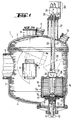
- FIG. 1 shows a gas-tight chamber 1 with a cylindrical jacket 2, a removable cover 3 and a bottom 4 shown, which over a suction nozzle 5 to a vacuum pump set, not shown connected.
- the chamber 1 can also not line shown are flooded with an inert gas.
- a melting and casting device 6 is arranged in the chamber 1, the can be tilted into the position 6a shown in broken lines for the purpose of emptying.
- a tilt axis 7 is provided, which at the same time as Coaxial bushing for melt flow and cooling water is formed.
- a loading opening 8 Above the melting position there is a loading opening 8 which expanded to a charging device by charging valves, not shown can be. Viewing windows 9 and 10 enable observations of the Melting and pouring process.
- the melting and pouring device 6 can also in a separate, not shown chamber can be housed, which is the chamber 1 upstream and from which the melt is transferred to chamber 1.
- the melting and casting device 6 can in this case also have several chambers Heaters 20 and molds 15 may be connected either in a row or in a circle or pitch circle around the melting and Pouring device 6 can be arranged around. In such a case the mold can be heated in one chamber in another chamber the casting into the mold, and again in one Another chamber of the cooling process of the mold, so that the optimal Melting and pouring device 6 are kept in constant use can.
- the melting and pouring device 6 can also be a transversely displaceable Cold wall crucibles are designed to be lockable Has bottom outlet opening for the melt, which move over the mold can be.
- Such, but not movable, arrangements are in the DE 44 20 138 A1 and DE 195 05 689 described and drawn.
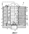
- a mold 15 which is designed as a centrifugal casting mold and is described in more detail with reference to FIGS. 2 and 3.
- the mold 15 has a support plate 16 which, with the interposition of a Thermal insulation 17 is attached to a turntable 18 which is not closer to designated cooling channels is equipped for water cooling, wherein the cooling water is supplied and discharged through the shaft 14.
- the mold 15 has a sprue 19 into which a heating device 20th is introduced, which is a meandering slotted hollow cylinder made of graphite is executed.
- the heating device 20 extends over the entire length or depth of the sprue 19 and depends on a coupling piece 21, this in turn via two rods 22 and 23, which also serve as feeders for Electricity and cooling water are used, connected to a motion drive 24 are, the drive motor is not shown. This makes the heater 20 can be raised and lowered in the direction of the double arrow 25.
- the rods 22 and 23 are passed gas-tight through a double sliding seal 26 is arranged at the upper end of a vertical pipe socket 27, in the the heating device 20 is at least partially retractable.
- Above the Mold 15 is - indicated by dash-dotted lines - a guide device 28 for the melt. In place of the two rods 22 and 23 can also kick a coaxial rod that has isolated current paths.
- the mold 15 consists of stacks of molds 29 arranged in several planes, each consisting of mold halves 29a and 29b, which have shoulder surfaces 30 with which the forms 29 are supported on sector-shaped abutments 31.
- the Molds 29 and abutments 31 are each in one plane between Spacer rings 32 arranged, and the stack of molds 29, abutments 31 and spacer rings 32 are already further by means of tie rods 33 Support plate 16 described above clamped with the rotary drive 13 connected is.
- the said stack passed further tie rods 34, which with the Turntable 18 are screwed.
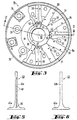
- the tie rods 33 and 34 are in two Cylinder surfaces of different diameters are arranged, which is shown in FIG. 3 is shown.
- the stacks of Forms 29, abutments 31 and spacers 32 from a clamping body Surround 35 which according to Figure 2 from individual clamping rings 35a and 35b is composed, which partially overlap each other in the axial direction.
- the upper clamping rings 35a are Z-shaped in cross section.
- the support plate 16 is in the center of the sprue 19 with one to the axis of rotation A-A concentric distributor body 36 provided the shape has a rounded cone at the top.
- the sprue 19 is from aligned, polygonal pipe sections 37 surrounded, which are held centrally by the spacer rings 32 and have 32 openings 38 between the spacer rings, each with one of the mold cavities 39 communicate.
- the mold cavities 39 are for Manufacture of valves 40 designed for internal combustion engines, wherein these valves are shown in Figures 5 and 6.
- the valves exist from a valve plate 40a and a stem 40b.
- the precision castings have different cross sections, and it can be seen that the Ends with the larger cross sections, namely with the valve plates 40a, the sprue 19 are facing.
- the mold has an inner diameter D i and an outer diameter D a , the circumference of which can be calculated.
- FIG. 4 now shows different temperature profiles between the inside diameter D i and the outside diameter D a .
- the heat radiation from the radiator 20 is indicated by the horizontal arrows 44.
- the dashed line 45 shows the temperature profile within the mold or along the molds 29 if these consist of a good heat-conducting material which enables temperature compensation between the inside and the outside.
- the dash-dotted line 46 shows the temperature profile when heated from the outside in connection with a material with a good heat conduction coefficient, such as copper.
- the line 47 consisting of crosses shows the situation when the heating direction is reversed, namely in the direction of the arrows 44 from the inside to the outside. It is still a relatively good heat-conducting material such as copper, so that a relatively very high outside temperature is established.
- Line 48 now illustrates the conditions of the subject matter of the invention, namely with strong heating in the direction of arrows 44 from the inside, ie from the sprue 19. Due to the relatively rapid heating in conjunction with a lower thermal conductivity than that of copper and in conjunction with the mass of the mold 15 increasing from the inside out, a relatively very steep temperature gradient is formed, specifically in the case of a mold with an outer diameter D a of approximately 500 mm and an inner diameter D i of approximately 150 mm and, when using molds 29 made of niobium, a temperature gradient corresponding to line 48 is set, which drops from an internal temperature of 800 ° C to an external temperature of 450 ° C.
- Figure 4 thus illustrates the synergistic effect of heating from the inside and the use of molded materials with a lower coefficient of thermal conductivity.
- the thermal conductivity coefficient of copper is 408 W / mK, but that of niobium is only 53.7 W / mK and that of tantalum is 57.5 W / mK, both at room temperature.
- Figure 5 now shows an axial section through a valve, along its axis clearly visible cavities 49 and cavities 50 have formed.
- Figure 6 shows an analog axial section through a valve that according to the invention Process was prepared, which is described in more detail below becomes.
- the outer surfaces of the stem and valve plate were smooth and bright, and corresponding micrographs showed a very uniform Grain size distribution and freedom from any voids, Pores, cavities or the like.
- a device according to FIG Figures 2 and 3 first evacuated to 10 -2 mbar and then flooded with argon to a pressure of about 400 mbar.
- the melting and casting device 6 which was designed as a cold wall crucible, 6 kg of a titanium alloy (titanium aluminide) with the composition 49% Ti, 47% Al, 2% Cr and 2% Nb (each atomic percent) were melted and brought to a temperature of 1650 ° C overheated.
- the heating device 20 which consisted of a meandering slotted graphite hollow cylinder, generated an output of 50 kW and was located in the sprue 19, the wall surface of the sprue 19 was heated to a temperature of 800 ° C. within 60 minutes.
- the melt was poured now within about 2 seconds into the mold 15, which was rotated at a speed of 800 min -1. After a few seconds, the valve blanks had solidified under control.
- the chamber 1 was then flooded with argon to a pressure of about 1 bar.
- valve blanks were exposed by gradually dismantling the cooled mold 15 from top to bottom and separating the sprue points on the material in the sprue 19.
- the valve blanks had a smooth and flawless surface. Longitudinal sections and micrographs showed that the valves were free from voids and porous spots and could be brought to their final state by simple post-processing.
- the mold 15 and the mold parts were in perfect condition and were suitable for recycling.
- centrifugal casting machine with a vertical axis of rotation A-A of the centrifugal casting mold 15
- inventive Device without leaving the concept of the invention can also be modified in such a way that the centrifugal casting mold 15 has a horizontal axis of rotation, but not in the drawing is particularly shown.
- the effective thermal conductivity coefficient of the mold materials or the mold components in the radial direction is preferably a maximum of 50%, in particular a maximum of 30%, of the thermal conductivity coefficient of pure copper.
Landscapes
- Engineering & Computer Science (AREA)
- Mechanical Engineering (AREA)
- Molds, Cores, And Manufacturing Methods Thereof (AREA)
Description
- Figur 1
- einen Vertikalschnitt durch die wesentlichen Teile einer vollständigen Vorrichtung,
- Figur 2
- einen Vertikalschnitt durch eine Kokille mit fünf Etagen zur gleichzeitigen Herstellung von insgesamt 60 Ventilen entlang der Linie II-II in Figur 3,
- Figur 3
- eine teilweise Draufsicht und einen teilweisen Horizontalschnitt durch den Gegenstand von Figur 2 entlang der Linie III-III,
- Figur 4
- ein Diagramm mit verschiedenen Temperaturverläufen zwischen dem Innendurchmesser und dem Außendurchmesser der Kokille nach Figur 2,
- Figur 5
- eine Axialschnitt durch ein Ventil für Verbrennungsmotoren, hergestellt nach einem Verfahren mit einer hohen Wärmeleitfähigkeit des Formwerkstoffs, und
- Figur 6
- einen Axialschnitt durch ein geometrisch identisches Ventil, hergestellt nach dem erfindungsgemäßen Verfahren und mit einer erfindungsgemäßen Kokille.
| Bezugszeichenliste | |||
| 1 | Kammer | 27 | Rohrstutzen |
| 2 | Mantel | 28 | Leiteinrichtung |
| 3 | Deckel | 29 | Formen |
| 4 | Boden | 29a, b | Formhälften |
| 5 | Saugstutzen | 30 | Schulterflächen |
| 6 | Schmelz- und Gießvorrichtung | 31 | Widerlager |
| 6a | Schmelz- und Gießvorrichtung | 32 | Distanzringe |
| 7 | Kippachse | 33 | Zuganker |
| 8 | Beschickungsöffnung | 34 | Zuganker |
| 9 | Einblickfenster | 35 | Spannkörper |
| 10 | Einblickfenster | 35a, b | Spannringe |
| 11 | Öffnung | 36 | Verteilerkörper |
| 12 | Verschlußplatte | 37 | Rohrabschnitte |
| 13 | Drehantrieb | 38 | Öffnungen |
| 14 | Welle | 39 | Formhohlraum |
| 15 | Kokille | 40 | Ventile |
| 16 | Tragplatte | 40a | Teller |
| 40b | Schaft | ||
| 17 | Wärmedämmung | 41 | Halbringe |
| 18 | Drehteller | 42 | Halbringe |
| 19 | Eingußkanal | 43 | Injektionsöffnung |
| 20 | Heizvorrichtung | 44 | Pfeile |
| 21 | Kupplungsstück | 45 | Linie |
| 22 | Stange | 46 | Linie |
| 23 | Stange | 47 | Linie |
| 24 | Bewegungsantrieb | 48 | Linie |
| 25 | Doppelpfeil | 49 | Hohlstellen |
| 26 | Gleitdichtung | 50 | Lunker |
Claims (20)
- Verfahren zum Herstellen von gesteuert erstarrten Präzisionsgußteilen durch Schleudergießen einer Schmelze unter Vakuum oder Schutzgas in eine vorgeheizte Kokille (15) mit einem zentralen Eingußkanal (19) und mehreren von diesem zum Außendurchmesser (Da) der Kokille (15) gerichteten Formhohlräumen (39), die von einem Werkstoff oder einer Werkstoffkombination mit einem Wärmeleitungskoeffizienten umgeben sind, der kleiner als der von Kupfer ist, dadurch gekennzeichnet, daß die Kokille (15) vor dem Abgießen der Schmelze vom Eingußkanal (19) her mit einer solchen Geschwindigkeit auf eine werkstoffbedingte Gießtemperatur des Eingußkanals (19) aufgeheizt wird, daß ein Temperaturgradient zwischen Innendurchmesser (Di) und Außendurchmesser (Da) der Kokille (15) mit von innen nach außen fallenden Temperaturen von mindestens 100 °C eingestellt wird.
- Verfahren nach Anspruch 1, dadurch gekennzeichnet, daß ein Temperaturgradient zwischen 200 °C und 600 °C, vorzugsweise zwischen 300 °C und 500 °C, eingestellt wird.
- Verfahren nach Anspruch 1, dadurch gekennzeichnet, daß die Temperatur der Wandung des Gießkanals (19) auf Werte zwischen 600 °C und 1000 °C und die Temperatur des Außendurchmessers (Da) der Kokille (15) auf Werte zwischen 300 °C und 600 °C eingestellt wird.
- Verfahren nach Anspruch 1, dadurch gekennzeichnet, daß beim Herstellen von Präzisionsgußteilen mit unterschiedlichen Querschnitten die Enden mit den größeren Querschnitten dem Eingußkanal (19) zugekehrt sind.
- Verwendung des Verfahrens nach mindestens einem der Ansprüche 1 bis 4 zum Herstellen von Präzisionsgußteilen aus Metallen aus der Gruppe Titan, Titanlegierungen mit mindestens 40 Gewichtsprozent Titan und aus Superlegierungen.
- Vorrichtung zur Durchführung des Verfahrens nach mindestens einem der vorhergehenden Ansprüche mit einer Schmelz- und Gießvorrichtung (6, 6a), mit einer Kammer (1), in der eine rotierbare Kokille (15) mit einem zentralen Eingußkanal (19) und mehreren von diesem zum Außendurchmesser (Da) der Kokille (15) gerichteten Formhohlräumen (39) und eine Heizvorrichtung (20) zum Vorheizen der Kokille (15) angeordnet sind, wobei die Kokille (15) aus einem Werkstoff oder einer Werkstoffkombination mit einem Wärmeleitungskoeffizienten besteht, der kleiner als der von Kupfer ist, dadurch gekennzeichnet, daß die Vorrichtung eine Bewegungseinrichtung aufweist, durch die die Heizvorrichtung (20) in den Eingußkanal (19) einführbar und aus diesem wieder herausziehbar ist.
- Vorrichtung nach Anspruch 6, dadurch gekennzeichnet, daß die Heizvorrichtung (20) für eine solche Heizleistung ausgelegt ist, daß die Kokille (15) vom Eingußkanal (19) her mit einer solchen Geschwindigkeit auf eine werkstoffbedingte Gießtemperatur der Wandung des Eingußkanals (19) aufheizbar ist, daß ein von innen nach außen fallender Temperaturgradient mindestens 100 °C beträgt.
- Vorrichtung nach Anspruch 6, dadurch gekennzeichnet, daß die Bewegungseinrichtung mindestens eine Stange (22, 23) aufweist, die gasdicht durch eine Gleitdichtung (26) in einem Deckel (3) der Kammer (1) hindurchgeführt ist, die zur Zufuhr des Heizstromes dient und deren äußeres Ende mit einem Bewegungsantrieb (24) verbunden ist.
- Vorrichtung nach Anspruch 6, dadurch gekennzeichnet, daß die Heizvorrichtung (20) als Widerstandsheizkörper ausgebildet ist, der durch direkten Stromdurchgang beheizbar ist.
- Vorrichtung nach Anspruch 6, dadurch gekennzeichnet, daß die Heizvorrichtung als Induktionsspule ausgebildet ist.
- Vorrichtung nach Anspruch 6, dadurch gekennzeichnet, daß die Kammer (1) eine Öffnung (11) aufweist, die durch eine Verschlußplatte (12) mit einem Drehantrieb (13) und einer Welle (14) für die Kokille (15) versehen ist.
- Vorrichtung nach Anspruch 6, dadurch gekennzeichnet, daß die Kokille (15) aus Stapeln von in mehreren Ebenen angeordneten Formen (29) besteht, die Schulterflächen (30) aufweisen, mit denen sich die Formen (29) an sektorförmigen Widerlagern (31) abstützen, daß die Formen (29) und die Widerlager (31) in jeweils einer Ebene zwischen Distanzringen (32) angeordnet sind und daß die Stapel von Formen (29), Widerlagern (31) und Distanzringen (32) mittels Zugankern (33, 34) gegen eine Tragplatte (16) verspannt sind, die mit dem Drehantrieb (13) drehfest verbunden ist.
- Vorrichtung nach Anspruch 12, dadurch gekennzeichnet, daß die Formen (29) aus Formhälften (29a, 29b) bestehen.
- Vorrichtung nach Anspruch 12, dadurch gekennzeichnet, daß die Stapel von Formen (29), Widerlagern (31) und Distanzringen (32) von einem Spannkörper (35) umgeben sind.
- Vorrichtung nach Anspruch 14, dadurch gekennzeichnet, daß der Spannkörper (35) aus einzelnen Spannringen (35a, 35b) zusammengesetzt ist, die einander in axialer Richtung teilweise überlappen.
- Vorrichtung nach Anspruch 15, dadurch gekennzeichnet, daß die oberen Spannringe (35a) im Querschnitt Z-förmig ausgebildet sind.
- Vorrichtung nach Anspruch 12, dadurch gekennzeichnet, daß die Tragplatte (6) im Zentrum des Eingußkanals (19) mit einem sich nach oben verjüngenden Verteilerkörper (36) für die Schmelze versehen ist.
- Vorrichtung nach Anspruch 6, dadurch gekennzeichnet, daß der Eingußkanal (19) von fluchtenden Rohrabschnitten (37) umgeben ist, die von den Distanzringen (32) zentrisch gehalten sind und die zwischen den Distanzringen (32) Öffnungen (38) aufweisen, die mit je einem Formhohlraum (39) kommunizieren.
- Vorrichtung nach Anspruch 6, dadurch gekennzeichnet, daß bei einer Kokille (15) zum Herstellen von Präzisionsgußteilen mit unterschiedlichen Querschnitten die Enden mit den größeren Querschnitten dem Eingußkanals (19) zugekehrt sind.
- Vorrichtung nach den Ansprüchen 18 und 19, dadurch gekennzeichnet, daß zwischen den Rohrabschnitten (37) und den Formen (29) aus Halbringen (41, 42) zusammengesetzte Düsenkörper für den Schmelzeeintritt in die Formhohlräume (39) angeordnet sind.
Applications Claiming Priority (2)
| Application Number | Priority Date | Filing Date | Title |
|---|---|---|---|
| DE19639514 | 1996-09-26 | ||
| DE19639514A DE19639514C1 (de) | 1996-09-26 | 1996-09-26 | Verfahren und Vorrichtung zum Herstellen von gesteuert erstarrten Präzisionsgußteilen durch Schleudergießen |
Publications (2)
| Publication Number | Publication Date |
|---|---|
| EP0835705A1 EP0835705A1 (de) | 1998-04-15 |
| EP0835705B1 true EP0835705B1 (de) | 2001-05-23 |
Family
ID=7806929
Family Applications (1)
| Application Number | Title | Priority Date | Filing Date |
|---|---|---|---|
| EP97114168A Expired - Lifetime EP0835705B1 (de) | 1996-09-26 | 1997-08-16 | Verfahren und Vorrichtung zum Herstellen von gesteuert erstarrten Präzisionsgussteilen durch Schleudergiessen |
Country Status (4)
| Country | Link |
|---|---|
| US (2) | US6250366B1 (de) |
| EP (1) | EP0835705B1 (de) |
| JP (1) | JP3267906B2 (de) |
| DE (2) | DE19639514C1 (de) |
Families Citing this family (42)
| Publication number | Priority date | Publication date | Assignee | Title |
|---|---|---|---|---|
| FR2789917B1 (fr) * | 1999-02-19 | 2001-06-15 | Centre Nat Rech Scient | Procede et dispositif de moulage de pieces en titane |
| DE19919869B4 (de) * | 1999-04-30 | 2009-11-12 | Alstom | Gussofen zur Herstellung von gerichtet ein- und polykristallin erstarrten Giesskörpern |
| CN1253275C (zh) * | 2001-06-11 | 2006-04-26 | 三德美国有限公司 | 真空下在各向同性石墨模具中离心浇铸金属合金 |
| US6755239B2 (en) * | 2001-06-11 | 2004-06-29 | Santoku America, Inc. | Centrifugal casting of titanium alloys with improved surface quality, structural integrity and mechanical properties in isotropic graphite molds under vacuum |
| DE10125129B4 (de) * | 2001-06-26 | 2006-01-26 | Ald Vacuum Technologies Ag | Permanentkokille für im Schleuderguß hergestellte Ventile für Hubkolbenmotore |
| DE10210001A1 (de) * | 2002-03-07 | 2003-10-02 | Mtu Aero Engines Gmbh | Verfahren und Vorrichtung zur maßgenauen Feingussherstellung von Bauteilen aus NE-Metalllegierungen sowie NE-Metalllegierungen zur Durchführung des Verfahrens |
| US6986381B2 (en) * | 2003-07-23 | 2006-01-17 | Santoku America, Inc. | Castings of metallic alloys with improved surface quality, structural integrity and mechanical properties fabricated in refractory metals and refractory metal carbides coated graphite molds under vacuum |
| EP2086704B1 (de) * | 2006-10-23 | 2011-08-17 | Manfred Renkel | Verfahren zur herstellung von feingussteilen durch schleuderguss |
| WO2008049452A1 (en) * | 2006-10-23 | 2008-05-02 | Manfred Renkel | Apparatus for centrifugal casting |
| ATE508820T1 (de) * | 2007-04-11 | 2011-05-15 | Manfred Renkel | Verfahren zur herstellung von feingussteilen durch schleuderguss |
| JP4872092B2 (ja) * | 2007-08-13 | 2012-02-08 | 独立行政法人産業技術総合研究所 | 微細熱電素子の製造方法 |
| GB2454010B (en) * | 2007-10-26 | 2009-11-11 | Castings Technology Internat | Casting a metal object |
| US20110094705A1 (en) * | 2007-11-27 | 2011-04-28 | General Electric Company | Methods for centrifugally casting highly reactive titanium metals |
| US20090133850A1 (en) * | 2007-11-27 | 2009-05-28 | General Electric Company | Systems for centrifugally casting highly reactive titanium metals |
| US8858697B2 (en) | 2011-10-28 | 2014-10-14 | General Electric Company | Mold compositions |
| KR101372299B1 (ko) * | 2011-11-03 | 2014-03-26 | 한국생산기술연구원 | 진공원심주조법을 이용한 연자성 비엠쥐 판재의 제조 장치 및 그 방법 |
| US9011205B2 (en) | 2012-02-15 | 2015-04-21 | General Electric Company | Titanium aluminide article with improved surface finish |
| US8932518B2 (en) | 2012-02-29 | 2015-01-13 | General Electric Company | Mold and facecoat compositions |
| US8906292B2 (en) | 2012-07-27 | 2014-12-09 | General Electric Company | Crucible and facecoat compositions |
| US8708033B2 (en) | 2012-08-29 | 2014-04-29 | General Electric Company | Calcium titanate containing mold compositions and methods for casting titanium and titanium aluminide alloys |
| US9038703B2 (en) * | 2012-10-09 | 2015-05-26 | T.H.T. Presses, Inc. | Production of die cast rotors with copper bars for electric motors |
| US8992824B2 (en) | 2012-12-04 | 2015-03-31 | General Electric Company | Crucible and extrinsic facecoat compositions |
| US9592548B2 (en) | 2013-01-29 | 2017-03-14 | General Electric Company | Calcium hexaluminate-containing mold and facecoat compositions and methods for casting titanium and titanium aluminide alloys |
| US9364890B2 (en) * | 2013-03-11 | 2016-06-14 | Ati Properties, Inc. | Enhanced techniques for centrifugal casting of molten materials |
| US9221096B2 (en) | 2013-03-11 | 2015-12-29 | Ati Properties, Inc. | Centrifugal casting apparatus and method |
| DE102013010739B4 (de) * | 2013-06-27 | 2019-08-08 | Audi Ag | Verfahren zum Herstellen eines Laufrads eines Abgasturboladers |
| US9511417B2 (en) | 2013-11-26 | 2016-12-06 | General Electric Company | Silicon carbide-containing mold and facecoat compositions and methods for casting titanium and titanium aluminide alloys |
| US9192983B2 (en) | 2013-11-26 | 2015-11-24 | General Electric Company | Silicon carbide-containing mold and facecoat compositions and methods for casting titanium and titanium aluminide alloys |
| US10391547B2 (en) | 2014-06-04 | 2019-08-27 | General Electric Company | Casting mold of grading with silicon carbide |
| DE102014222989A1 (de) * | 2014-11-11 | 2016-05-12 | Bayerische Motoren Werke Aktiengesellschaft | Formkörper |
| DE102015100807B4 (de) * | 2015-01-20 | 2018-11-29 | Buderus Guss Gmbh | Schleudergusskokillenvorrichtung zur Herstellung von Bremsscheiben und deren Verwendung |
| CN104874760A (zh) * | 2015-05-21 | 2015-09-02 | 凤冈县凤鸣农用机械制造有限公司 | 真空离心铸造设备 |
| DE102015211718B4 (de) | 2015-06-24 | 2020-12-03 | MTU Aero Engines AG | Verfahren und Vorrichtung zur Herstellung von TiAl-Schmiedebauteilen |
| CN107186193B (zh) * | 2016-03-14 | 2019-08-09 | 上海海立电器有限公司 | 真空炉离心铸造工艺及其设备 |
| CN108941497A (zh) * | 2018-08-28 | 2018-12-07 | 上海化工研究院有限公司 | 微型透平压缩机用多级涡轮转子的铸造装置及铸造方法 |
| CN109746406B (zh) * | 2019-03-14 | 2020-12-15 | 明光天赋智能科技有限公司 | 一种异型铁铸件离心铸造机 |
| CN110842168B (zh) * | 2019-09-10 | 2023-10-27 | 浙江大学 | 搭载于超重力离心机的定向凝固熔铸系统 |
| CN112059151A (zh) * | 2020-08-12 | 2020-12-11 | 西北工业大学 | 一种在真空熔铸设备内实现型壳加热与保温的方法与装置 |
| CN112059136A (zh) * | 2020-08-12 | 2020-12-11 | 西北工业大学 | 一种真空离心铸造设备快速装卸型壳的方法及装卸装置 |
| CN112846126B (zh) * | 2020-12-31 | 2022-05-17 | 北京科技大学 | 多组元径向功能梯度材料设备的熔体流速调节系统及方法 |
| CN114309550A (zh) * | 2021-12-31 | 2022-04-12 | 江苏永瀚特种合金技术股份有限公司 | 基于局域区域温度可调系统整体细晶铸造的装置及其方法 |
| CN114653918B (zh) * | 2022-04-13 | 2024-06-21 | 扬州市雪龙铜制品有限公司 | 一种大型铜套离心铸造方法及铸造设备 |
Family Cites Families (11)
| Publication number | Priority date | Publication date | Assignee | Title |
|---|---|---|---|---|
| US1630043A (en) * | 1925-06-05 | 1927-05-24 | Augusta M Wetmore | Centrifugal casting |
| DE596674C (de) * | 1932-11-04 | 1934-05-08 | Osnabruecker Kupfer Und Drahtw | Schleudergusskokille zum Herstellen rohrartiger Koerper |
| CH577864A5 (de) * | 1974-05-29 | 1976-07-30 | Sulzer Ag | |
| JPS5677058A (en) * | 1979-11-27 | 1981-06-25 | Toyota Motor Corp | Preheating method of die-casting die |
| US4635701A (en) * | 1983-07-05 | 1987-01-13 | Vida-Weld Pty. Limited | Composite metal articles |
| JPH03174965A (ja) * | 1989-12-01 | 1991-07-30 | Ube Ind Ltd | 射出成形方法および装置 |
| US5119865A (en) * | 1990-02-20 | 1992-06-09 | Mitsubishi Materials Corporation | Cu-alloy mold for use in centrifugal casting of ti or ti alloy and centrifugal-casting method using the mold |
| JP3174965B2 (ja) | 1992-01-13 | 2001-06-11 | 東洋ラジエーター株式会社 | 車両用ラジエータの取付構造 |
| DE19505689C2 (de) * | 1995-02-20 | 2003-10-02 | Ald Vacuum Techn Ag | Gießform zum Herstellen von Gußteilen aus reaktiven Metallen |
| DE4420138C2 (de) * | 1994-06-09 | 1997-09-25 | Ald Vacuum Techn Gmbh | Verfahren zum Herstellen von Gußteilen aus reaktiven Metallen und aus Metall bestehende Kokille zur Durchführung des Verfahrens |
| DE59507205D1 (de) * | 1994-06-09 | 1999-12-16 | Ald Vacuum Techn Gmbh | Verfahren zum Herstellen von Gussteilen aus reaktiven Metallen und wiederverwendbare Giessform zur Durchführung des Verfahrens |
-
1996
- 1996-09-26 DE DE19639514A patent/DE19639514C1/de not_active Expired - Fee Related
-
1997
- 1997-08-16 EP EP97114168A patent/EP0835705B1/de not_active Expired - Lifetime
- 1997-08-16 DE DE59703587T patent/DE59703587D1/de not_active Expired - Fee Related
- 1997-09-25 JP JP25986397A patent/JP3267906B2/ja not_active Expired - Fee Related
- 1997-09-26 US US08/937,995 patent/US6250366B1/en not_active Expired - Fee Related
-
2001
- 2001-05-04 US US09/849,045 patent/US6408929B2/en not_active Expired - Fee Related
Also Published As
| Publication number | Publication date |
|---|---|
| DE19639514C1 (de) | 1997-12-18 |
| JPH1099955A (ja) | 1998-04-21 |
| US6408929B2 (en) | 2002-06-25 |
| JP3267906B2 (ja) | 2002-03-25 |
| US20010045267A1 (en) | 2001-11-29 |
| EP0835705A1 (de) | 1998-04-15 |
| US6250366B1 (en) | 2001-06-26 |
| DE59703587D1 (de) | 2001-06-28 |
Similar Documents
| Publication | Publication Date | Title |
|---|---|---|
| EP0835705B1 (de) | Verfahren und Vorrichtung zum Herstellen von gesteuert erstarrten Präzisionsgussteilen durch Schleudergiessen | |
| EP0686443B1 (de) | Verfahren zum Herstellen von Gussteilen aus reaktiven Metallen und wiederverwendbare Giessform zur Durchführung des Verfahrens | |
| EP0992305B1 (de) | Verfahren und Vorrichtung zum Herstellen von Präzisionsgussteilen durch Schleudergiessen | |
| DE19607805C1 (de) | Verfahren und Vorrichtung zum Schmelzen und Gießen von Metallen in Formen | |
| DE112010002758B4 (de) | Ermüdungsresistente gegossene gegenstände aus titanlegierung | |
| DE2230317C2 (de) | Verfahren zum Gießen von metallenen Werkstücken, insbesondere Turbinenschaufeln | |
| DE2735928C3 (de) | Verfahren zum Gießen eines Formteils aus einem temperaturbeständigen metallischen Verbundwerkstoff und Vorrichtung zur Durchführung des Verfahrens | |
| DE69923930T2 (de) | Vorrichtung zum Druckgiessen von Material mit hohem Schmelzpunkt | |
| EP3225330B1 (de) | Kokille zum giessen eines konturierten metallgegenstandes, insbesondere aus tial | |
| EP0462409B1 (de) | Verfahren zur Herstellung rohrförmiger Formteile aus Hochtemperatur-Supraleiter-Material sowie eine Anlage zu seiner Durchführung | |
| DE2926194C1 (de) | Giessvorrichtung zur Herstellung metallischer Gussstuecke mit orientierter Struktur | |
| DE2231807A1 (de) | Huelse als zylindrische druckkammer fuer spritzgussmaschinen | |
| DE3546148A1 (de) | Vorrichtung zur herstellung von verbundwerkstoff | |
| EP1480770B1 (de) | Verfahren und vorrichtung zur massgenauen feingussherstellung von bauteilen aus ne-metalllegierungen | |
| EP0255475B1 (de) | Füllbüchse für Druckgiessmaschinen | |
| EP0872295A1 (de) | Giessform und Verfahren zum Herstellen von metallischen Hohlgiesslingen sowie Hohlgiesslinge | |
| DE2952150A1 (de) | Verfahren und vorrichtung zur herstellung von barren aus metallischen verbundwerkstoffen durch gerichtetes erstarren | |
| DE69503145T2 (de) | Verfahren zur herstellung einer bimetallische rolle einer zerkleinerungsanlage | |
| DE19528291C2 (de) | Verfahren und Vorrichtung zum Herstellen von Partikeln aus gerichtet erstarrten Gußkörpern | |
| DE3050243A1 (en) | Method of producing an article and article produced in a mould which defines the contour of the article | |
| DE3300701A1 (de) | Druckguss-verfahren und vorrichtung zu seiner durchfuehrung | |
| EP2173507B1 (de) | Verfahren und vorrichtung zur herstellung eines rohrförmigen festkörpers aus einer hochschmelzenden wolfram- schwermetalllegierung, insbesondere als halbzeug für die fertigung eines penetrators für ein wuchtgeschoss mit splitterwirkung | |
| DE4420138C2 (de) | Verfahren zum Herstellen von Gußteilen aus reaktiven Metallen und aus Metall bestehende Kokille zur Durchführung des Verfahrens | |
| DE19505689C2 (de) | Gießform zum Herstellen von Gußteilen aus reaktiven Metallen | |
| DE10120493C1 (de) | Verfahren und Vorrichtung zum Herstellen von Präzisionsgußteilen |
Legal Events
| Date | Code | Title | Description |
|---|---|---|---|
| PUAI | Public reference made under article 153(3) epc to a published international application that has entered the european phase |
Free format text: ORIGINAL CODE: 0009012 |
|
| AK | Designated contracting states |
Kind code of ref document: A1 Designated state(s): DE FR GB IT SE |
|
| AX | Request for extension of the european patent |
Free format text: AL;LT;LV;RO;SI |
|
| 17P | Request for examination filed |
Effective date: 19980916 |
|
| AKX | Designation fees paid |
Free format text: DE FR GB IT SE |
|
| RBV | Designated contracting states (corrected) |
Designated state(s): DE FR GB IT SE |
|
| 17Q | First examination report despatched |
Effective date: 19990222 |
|
| RAP1 | Party data changed (applicant data changed or rights of an application transferred) |
Owner name: W.C. HERAEUS GMBH & CO. KG Owner name: ALD VACUUM TECHNOLOGIES GMBH |
|
| RAP1 | Party data changed (applicant data changed or rights of an application transferred) |
Owner name: W.C. HERAEUS GMBH & CO. KG Owner name: ALD VACUUM TECHNOLOGIES AG |
|
| GRAG | Despatch of communication of intention to grant |
Free format text: ORIGINAL CODE: EPIDOS AGRA |
|
| GRAG | Despatch of communication of intention to grant |
Free format text: ORIGINAL CODE: EPIDOS AGRA |
|
| GRAH | Despatch of communication of intention to grant a patent |
Free format text: ORIGINAL CODE: EPIDOS IGRA |
|
| GRAH | Despatch of communication of intention to grant a patent |
Free format text: ORIGINAL CODE: EPIDOS IGRA |
|
| GRAA | (expected) grant |
Free format text: ORIGINAL CODE: 0009210 |
|
| ITF | It: translation for a ep patent filed | ||
| AK | Designated contracting states |
Kind code of ref document: B1 Designated state(s): DE FR GB IT SE |
|
| GBT | Gb: translation of ep patent filed (gb section 77(6)(a)/1977) |
Effective date: 20010523 |
|
| REF | Corresponds to: |
Ref document number: 59703587 Country of ref document: DE Date of ref document: 20010628 |
|
| ET | Fr: translation filed | ||
| REG | Reference to a national code |
Ref country code: GB Ref legal event code: IF02 |
|
| PLBE | No opposition filed within time limit |
Free format text: ORIGINAL CODE: 0009261 |
|
| STAA | Information on the status of an ep patent application or granted ep patent |
Free format text: STATUS: NO OPPOSITION FILED WITHIN TIME LIMIT |
|
| 26N | No opposition filed | ||
| REG | Reference to a national code |
Ref country code: FR Ref legal event code: CJ |
|
| PGFP | Annual fee paid to national office [announced via postgrant information from national office to epo] |
Ref country code: GB Payment date: 20060824 Year of fee payment: 10 |
|
| PGFP | Annual fee paid to national office [announced via postgrant information from national office to epo] |
Ref country code: IT Payment date: 20060831 Year of fee payment: 10 |
|
| PGFP | Annual fee paid to national office [announced via postgrant information from national office to epo] |
Ref country code: DE Payment date: 20070822 Year of fee payment: 11 |
|
| PGFP | Annual fee paid to national office [announced via postgrant information from national office to epo] |
Ref country code: SE Payment date: 20060814 Year of fee payment: 10 |
|
| EUG | Se: european patent has lapsed | ||
| GBPC | Gb: european patent ceased through non-payment of renewal fee |
Effective date: 20070816 |
|
| PG25 | Lapsed in a contracting state [announced via postgrant information from national office to epo] |
Ref country code: SE Free format text: LAPSE BECAUSE OF NON-PAYMENT OF DUE FEES Effective date: 20070817 |
|
| PGFP | Annual fee paid to national office [announced via postgrant information from national office to epo] |
Ref country code: FR Payment date: 20070812 Year of fee payment: 11 |
|
| PG25 | Lapsed in a contracting state [announced via postgrant information from national office to epo] |
Ref country code: GB Free format text: LAPSE BECAUSE OF NON-PAYMENT OF DUE FEES Effective date: 20070816 |
|
| REG | Reference to a national code |
Ref country code: FR Ref legal event code: ST Effective date: 20090430 |
|
| PG25 | Lapsed in a contracting state [announced via postgrant information from national office to epo] |
Ref country code: FR Free format text: LAPSE BECAUSE OF NON-PAYMENT OF DUE FEES Effective date: 20080901 Ref country code: DE Free format text: LAPSE BECAUSE OF NON-PAYMENT OF DUE FEES Effective date: 20090303 |
|
| PG25 | Lapsed in a contracting state [announced via postgrant information from national office to epo] |
Ref country code: IT Free format text: LAPSE BECAUSE OF NON-PAYMENT OF DUE FEES Effective date: 20070816 |