EP0833485B1 - Network communication - Google Patents
Network communication Download PDFInfo
- Publication number
- EP0833485B1 EP0833485B1 EP19970307025 EP97307025A EP0833485B1 EP 0833485 B1 EP0833485 B1 EP 0833485B1 EP 19970307025 EP19970307025 EP 19970307025 EP 97307025 A EP97307025 A EP 97307025A EP 0833485 B1 EP0833485 B1 EP 0833485B1
- Authority
- EP
- European Patent Office
- Prior art keywords
- node
- network
- address
- packets
- arp
- Prior art date
- Legal status (The legal status is an assumption and is not a legal conclusion. Google has not performed a legal analysis and makes no representation as to the accuracy of the status listed.)
- Expired - Lifetime
Links
Images


Classifications
-
- H—ELECTRICITY
- H04—ELECTRIC COMMUNICATION TECHNIQUE
- H04L—TRANSMISSION OF DIGITAL INFORMATION, e.g. TELEGRAPHIC COMMUNICATION
- H04L12/00—Data switching networks
- H04L12/28—Data switching networks characterised by path configuration, e.g. LAN [Local Area Networks] or WAN [Wide Area Networks]
-
- H—ELECTRICITY
- H04—ELECTRIC COMMUNICATION TECHNIQUE
- H04L—TRANSMISSION OF DIGITAL INFORMATION, e.g. TELEGRAPHIC COMMUNICATION
- H04L12/00—Data switching networks
- H04L12/28—Data switching networks characterised by path configuration, e.g. LAN [Local Area Networks] or WAN [Wide Area Networks]
- H04L12/40—Bus networks
- H04L12/40052—High-speed IEEE 1394 serial bus
- H04L12/40091—Bus bridging
-
- H—ELECTRICITY
- H04—ELECTRIC COMMUNICATION TECHNIQUE
- H04L—TRANSMISSION OF DIGITAL INFORMATION, e.g. TELEGRAPHIC COMMUNICATION
- H04L61/00—Network arrangements, protocols or services for addressing or naming
-
- H—ELECTRICITY
- H04—ELECTRIC COMMUNICATION TECHNIQUE
- H04L—TRANSMISSION OF DIGITAL INFORMATION, e.g. TELEGRAPHIC COMMUNICATION
- H04L12/00—Data switching networks
- H04L12/28—Data switching networks characterised by path configuration, e.g. LAN [Local Area Networks] or WAN [Wide Area Networks]
- H04L12/46—Interconnection of networks
- H04L12/4604—LAN interconnection over a backbone network, e.g. Internet, Frame Relay
- H04L12/4608—LAN interconnection over ATM networks
-
- H—ELECTRICITY
- H04—ELECTRIC COMMUNICATION TECHNIQUE
- H04L—TRANSMISSION OF DIGITAL INFORMATION, e.g. TELEGRAPHIC COMMUNICATION
- H04L61/00—Network arrangements, protocols or services for addressing or naming
- H04L61/09—Mapping addresses
- H04L61/10—Mapping addresses of different types
-
- H—ELECTRICITY
- H04—ELECTRIC COMMUNICATION TECHNIQUE
- H04L—TRANSMISSION OF DIGITAL INFORMATION, e.g. TELEGRAPHIC COMMUNICATION
- H04L61/00—Network arrangements, protocols or services for addressing or naming
- H04L61/58—Caching of addresses or names
Definitions
- This invention relates to a method of communicating over a network, a network, an ARP or RARP response packet, and an apparatus for use as a network node.
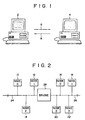
- Fig. 1 transmissions directed from a first general purpose computer 2 to a second general purpose computer 4 are indicated by an arrow 6.
- communications directed from the second computer to the first computer are indicated by an arrow 8.
- an electronic bus such as an IEEE-1394 serial bus, interconnects computers 2 and 4, and is used to channel transmissions between the computers.
- the transmissions are abstractly represented by arrows 6 and 8.
- Fig. 1 shows only two computers, the network represented in Fig. 1 may be made up of more than two computers.
- Fig. 1 is referenced below for purposes of describing ARP and RARP communication in more detail.
- ARP may be used when a first network computer wishes to communicate with a second network computer but does not know the second computer's physical address.
- computer 2 may wish to communicate with computer 4 but has only computer 4's internet protocol address (or "IP address") and not computer 4's physical address.
- IP address internet protocol address
- computer 2 broadcasts an "ARP request" (represented by arrow 6) over the network bus.
- the request includes the IP address of computer 4.
- computer 4 recognizes that it is the intended recipient of the request.
- Computer 4 transmits an "ARP response" (represented by arrow 8), which is addressed to computer 2 and contains computer 4's physical address.
- RARP may be used when a network computer wishes to determine its IP address through the network.
- computer 2 wishing to determine its IP address, broadcasts a "RARP request" (represented by arrow 6) over the network.
- the RARP request includes the IP address of computer 4, as well as the physical address of computer 2.
- computer 4 determines that it is the intended recipient of the RARP request - through examination of the IP address - it determines the IP address of computer 2 by cross-referencing computer 2's physical address to computer 2's IP address and then transmits a "RARP response" (represented by arrow 8), which includes the IP address of computer 2.
- ARP ARP
- a requesting node In ARP, a requesting node is limited to acquiring the physical address of a target node, and cannot acquire information that would facilitate communication between itself and the target node. In particular, the requesting node cannot acquire the address within the target computer of the application which is the subject of the request.
- FIG. 1 for example once computer 2 determines the physical address of computer 4, communication between the two computers may proceed, but each time computer 4 receives a communication packet from computer 2, computer 4's processing unit (CPU) must examine the received packet and then forward the packet to an appropriate application within its memory.
- the size of the communication packets is limited in ARP, further limiting flexibility.
- a drawback of RARP is its sensitivity to bus resets.
- a network bus is reset- such as when the power supply is toggled, or a new device is connected to the network - the physical addresses of the network nodes may change, resulting in the generation of incorrect cross-references by nodes generating RARP responses, thereby resulting in the transmission of incorrect IP addresses to requesting nodes.
- a first aspect of the present invention provides a method for implementing communication over a network having a plurality of nodes, comprising the steps of: transmitting an ARP request packet from a first network node to a second network node; and transmitting an ARP response packet from said second node to said first node; wherein said response packet includes a physical address and an offset address, said physical address indicating the location within the network where said second node is located and said offset address indicating a location within said second node where an application program processes communication packets.
- a second aspect of the present invention provides a communications network having plurality of nodes, including: first means arranged to transmit an ARP request packet from a first network node to a second network node; and second means arranged to transmit an ARP response packet from said second node to said first node; wherein said response packet includes a physical address and an offset address, said physical address indicating the location within the network where said second node is located and said offset address indicating a location within said second node where an application program processes communication packets.
- a third aspect of the present invention provides an ARP response packet which includes a physical address indicating a location in a network of a node producing the response packet, and an offset address indicating a location within the said node of an application program for processing communication packets.
- a fourth aspect of the present invention provides apparatus for use as a node in a communications network, the apparatus comprising means arranged to produce, in response to a received ARP request packet, an ARP response packet which includes the physical address of the apparatus and an offset address indicating the location within the apparatus of an application program for processing communication packets.
- Including an offset address in the response packet allows subsequent communication packets to be addressed directly to the application program and allows the subsequent packets to be of variable size.
- the ARP type communication session is initiated through request and response packets
- the response packet includes an offset address specifying the location of the software application that is the subject of the session.
- a fifth aspect of the invention provides a method for implementing communication over a network having a plurality of nodes, comprising the steps of: transmitting a Reverse Address Resolution Protocol request packet from a first network node to a second network node said request packet including a node unique ID identifying said first node; and transmitting a Reverse Address Resolution Protocol response packet from said second node to said first node; wherein said response packet includes a physical address and an offset address, said physical address indicating the location within the network where said second node is located and said offset address indicating a location within said second node where an application program processes communication packets.
- a sixth aspect of the invention provides a communications network having plurality of nodes, including: first means arranged to transmit a Reverse Address Resolution Protocol request packet from a first network node to a second network node said request packet including a node unique ID identifying said first node; and second means arranged to transmit a Reverse Address Resolution Protocol response packet from said second node to said first node; wherein said response packet includes a physical address and an offset address, said physical address indicating the location within the network where said second node is located and said offset address indicating a location within said second node where an application program processes communication packets.
- each network node is assigned a node unique ID for the purpose of providing an unchanging identifier for each node, thereby, providing an unchanging physical address reference for use in RARP type requests, and allowing RARP type communication to be conducted without interference from network resets.
- buses 24 and 26 are referred to as buses "0" and “1", respectively.
- Nodes 10, 12 and 14 are referred to as nodes “0", “1” and “2”, respectively, and nodes 16, 18, 20 and 22 are referred to as nodes “0", “1", “2” and “3”, respectively - any two nodes having the same ID being distinguished by the busses to which they are coupled.
- each of nodes 10-22 is assigned a node unique ID which is sufficient to uniquely identify each node without referring to bus IDs and/or node IDs.
- the bus IDs, node IDs and node unique IDs are stored in an address cache table along with the node IP addresses. Preferably, a copy of the address cache table is stored within each network node.
- FIG. 3 An exemplary address cache table corresponding to the network of Fig. 2 is shown in Fig. 3.
- One way in which each of the network nodes may acquire the address cache table is through ARP type signaling. That is, in the course of conducting an ARP type session, a responding node may send the requesting node its bus ID, node ID, node unique ID, and IP address, which the requesting node then stores in its address cache table.
- the requesting node's table may or may not contain updated information for all nodes in the network.
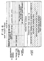
- Figs. 4 and 5 show illustrative ARP type communication packets in accordance with the invention.
- Fig. 4 shows an ARP type request packet
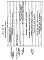
- Fig. 5 shows an ARP type response packet.
- the ARP request and response packets are asynchronous packets.
- Each packet includes five primary divisions: an asynchronous packet header 30, a stream type 32, a Logical Link Control/SNAP (LLC/SNAP) header 34, an ARP/RARP header 36, and ARP/RARP data 38.
- LLC/SNAP Logical Link Control/SNAP
- Each of the primary divisions are, in turn, divided into one or more horizontal subdivisions having a length of four bytes each.
- the first item included in the asynchronous packet header is a broadcast bus indicator (e.g. 10 bits representing the string 0x3FE) for indicating which bus or buses in the network should receive the request packet (e.g. all - buses 0 and 1).
- the next item is a broadcast node indicator (e.g. 6 bits representing the string 0x3F) for indicating which node or nodes in the network should receive the request (e.g. all - nodes 10-22).
- the broadcast node indicator is a source ID which is the node ID of the node that transmits the request.
- a destination offset e.g. 6 bytes representing the string 0xFFFF FFFFFF FF
- the stream type (ST) division includes a communication type indicator (e.g. bits representing the string 0x00) for indicating the type of communication to which the request packet is related (e.g. Logical Link Control - ARP/RARP/IP).
- a communication type indicator e.g. bits representing the string 0x00
- Logical Link Control - ARP/RARP/IP e.g. Logical Link Control - ARP/RARP/IP
- the LLC/SNAP header division includes a resolution protocol indicator (e.g. bits representing the string 0x0806) for indicating the type of protocol to which the request packet is related (i.e. ARP).
- a resolution protocol indicator e.g. bits representing the string 0x0806
- the ARP header division includes a protocol type indicator and an operation indicator.
- the protocol type indicator contains information (e.g. bits representing the string 0x0800) for indicating the protocol to which the request packet is related (e.g. IP protocol).
- the operation indicator contains information indicating the type of operation to which the packet is related (i.e. ARP request).
- the ARP data division of the ARP request packet will be described.
- the first item included in the ARP data division is a transmitter address, indicating the address of the node that transmitted the ARP request packet.
- the transmitter address may be, for example, a 64 bit address, with the first 16 bits indicating the node ID of the transmitting node and the following 48 bits indicating a requesting node offset address, the requesting node offset address being an address within the transmitting node's memory where communication packets are processed (e.g.the address of an application program).
- the second item in the ARP data division is the node unique ID of the transmitting node (e.g. 64 bits).
- the third item is the IP address of the transmitting node (e.g. 32 bits), and the fourth item is the IP address (e.g. 32 bits) of the node that is the intended recipient of the request packet.
- the ARP data division may include areas for a destination address and a node unique ID of the destination node. These areas are analogous to those provided for the transmitter address and the node unique ID of the transmitting node, respectively. However, since the request packet is broadcast, the destination areas are indefinite, and therefore are not filled with actual addresses. In an exemplary embodiment, the destination address and destination unique ID areas are 64 bit areas that are filled with zeros to indicate their indefinite state.
- error checking bit(s) may be included within the request packet. These bits may be for detecting and/or correcting errors within the packet through implementation of an error checking code, such as a cyclic redundancy code (CRC). Moreover, multiple groups of error checking bits may be included within the packet, with each group dedicated to detecting and/or correcting errors within a distinct portion of the packet.
- the ARP header division may include a first group of dedicated error checking bits for use in detecting and/or correcting errors in the header division's contents, while the ARP data division may include a second group of dedicated error checking bits for use in detecting and/or correcting errors in the data division's contents.
- the ARP response packet will now be described with reference to Fig. 5. It can be seen from Fig. 5 that the first item included in the asynchronous packet header is a transmitter node ID (e.g. 16 bits) which is the node ID of the node that transmitted the ARP request packet prompting the response. The next item is a response source ID (e.g. 16 bits) which is the node ID of the node transmitting the response packet. Following the response source ID is a response destination offset (e.g. 6 bytes) which indicates the location within the memory of the responding node where the_protocol specified by the "protocol type" indicator is processed.
- a transmitter node ID e.g. 16 bits
- response source ID e.g. 16 bits
- response destination offset e.g. 6 bytes
- the stream type (ST), LLC/SNAP header, and ARP header divisions of the response packet are similar to the ST, LLC/SNAP header, and ARP header divisions of the request packet.
- the ST division of the response packet includes a communication type indicator (e.g. bits representing the string 0x00) for indicating the type of communication to which the request packet is related (e.g. Logical Link Control - ARP/RARP/IP).
- the LLC/SNAP header division includes a resolution protocol indicator (e.g. bits representing the string 0x0806) for indicating the type of protocol to which the request packet is related (i.e. ARP).
- the ARP header division of the response packet includes a protocol type indicator and an operation indicator - the protocol type indicator containing information (e.g. bits representing the string 0x0800) for indicating the protocol to which the response packet is related (e.g. IP protocol), and the operation indicator containing information indicating the type of operation to which the packet is related (i.e. ARP response).
- the ARP data division of the ARP response packet will be described.
- the first item included in the ARP data division is a response transmitter address, indicating the address of the node that transmitted the ARP response packet.
- the response transmitter address may be, for example, a 64 bit address, with the first 16 bits indicating the node ID of the responding node and the following 48 bits indicating a responding node offset address, the responding node offset address being an address within the responding node's memory where communication packets are processed (e.g. the address of an application program).
- the second item in the ARP data division is the node unique ID of the response transmitting node (e.g. 64 bits).
- the third item is the IP address of the response transmitting node (e.g. 32 bits), and the fourth item is the IP address (e.g. 32 bits) of the node that is the intended recipient of the response packet.
- the ARP data division of the response packet further includes the address of the intended recipient of the response packet (i.e. the requesting node) and the node unique ID of the intended recipient.
- the format for these additional items may be analogous to the format for the request transmitter address and the request transmitter node unique ID, respectively.
- the responding node may simply use the first two items of the request packet's ARP data as the additional items in the response packet, thereby facilitating formation of the response packet.
- the response packet optionally includes error checking bit(s). These bits may be for detecting and/or correcting errors within the packet through implementation of an error checking code, such as a cyclic redundancy code (CRC). Moreover, multiple groups of error checking bits may included within the packet, with each group dedicated to detecting and/or correcting errors within a distinct portion of the packet.
- the ARP header division may include a first group of dedicated error checking bits for use in detecting and/or correcting errors in the header division's contents, while the ARP data division may include a second group of dedicated error checking bits for use in detecting and/or correcting errors in the data division's contents.
- node 0 on bus 0 (or "node 10" as indicated in Fig. 2) wants to know the physical address of the node having an IP address of 4 (or “node 18" as indicated by Fig. 2). Accordingly, node 10 broadcasts an ARP request packet having the format shown in Fig. 4 to all of the nodes in the network - the packet being transmitted to the nodes in bus 1 via the bridge (see Fig. 2). As mentioned above, the request packet includes a destination offset in the ARP header division, and a destination IP address in the ARP data division. In the present illustration the ARP data includes a destination IP address of "4".
- each node in the network Upon reception of the broadcast request packet, each node in the network sends the ARP data of the packet to the address indicated by the destination offset. Each node then reviews the destination IP address indicated in the ARP data of the request, and if the destination IP address does not match the reviewing node's IP address the reviewing node ignores the request. If the destination IP address does match the reviewing node's IP address, the reviewing node generates an ARP response packet like the one shown in Fig. 5. Thus, when node 18 checks the destination IP address of the request packet, it determines that it is the intended recipient and proceeds to generate an ARP response packet.
- the node generating the response packet may form the response destination offset (48 bits) by extracting the response source ID (16 bits) from the response transmitter address (64 bits).
- ARP type communication in accordance with the invention has advantages over prior ARP systems.
- One advantage is a reduced computational burden on the responding node's CPU which results from the inclusion of a responding node offset address in the response packet. More, particularly, including the responding node offset address in the response packet allows the requesting node to acquire the responding node offset address, and thereafter transmit information directly to an application program located at the offset address. Thereby, allowing the responding node's CPU to be bypassed.
- Another advantage is the ability to accommodate various length ARP packets.
- including the responding node offset address in the response packet allows the responding node's CPU to be relieved of having to interpret subsequently received packets. Therefore, packets received at the responding node do not need to be temporarily stored in the responding node's CPU buffer, and the size of the packets that can be used is not limited by the size of CPU buffer (i.e. the packets do not need to fit into the CPU buffer). Accordingly, the invention provides greater packet length flexibility.
- Figs. 6 and 7 show an illustrative RARP type request packet in accordance with the invention and an illustrative RARP type response packet in accordance with the invention, respectively.
- RARP type communication may be implemented in the network of Fig. 2, using the address cache table of Fig. 3.
- the RARP type packets of Figs. 6 and 7 are similar to the ARP packets of Figs. 4 and 5, respectively, and therefore only the differences between the respective ARP and RARP packets will be discussed.
- the RARP request packet includes the same five primary divisions as the ARP request packet but differs from the ARP request packet in three of the primary divisions.
- the RARP LLC/SNAP header division includes a resolution protocol indicator (e.g. bits representing the string 0x8035) indicating that the type of protocol to which the request packet is related is RARP - rather than ARP.
- the RARP header division includes an operation indicator containing information indicating that the type of operation to which the packet is related is RARP request - rather than ARP request.
- the RARP data division does not include the IP address of the transmitter node, but rather includes some indicator that the IP address of the transmitter is indefinite (e.g. bits indicating a string of zeros). The absence of the requesting node's IP address is consistent with RARP operation since the very reason RARP requests are generated is so that the requesting node can determine its own IP address.
- the RARP response packet differs from the ARP response packet in two of the primary divisions.
- the RARP LLC/SNAP header division includes a resolution protocol indicator (e.g. bits representing the string 0x8035) indicating that the type of protocol to which the request packet is related is RARP - rather than ARP; and the RARP header division includes an operation indicator containing information indicating that the type of operation to which the packet is related is RARP response - rather than ARP response.
- a node which wants to determine its own IP address When a RARP type communication is initiated, a node which wants to determine its own IP address generates a RARP request packet as described above.
- the RARP request is broadcast to all nodes in the network (e.g. the network of Fig. 2) and a node which is assigned to respond to RARP requests (e.g. a server) determines the IP address of the requesting node and generates a RARP response.
- the RARP response node In determining the IP address of the requesting node, the RARP response node first determines the requesting nodes physical address by referencing the transmitter node's node ID as set forth in the RARP request's asynchronous packet header, alternatively, by referencing the transmitter node's node unique ID as set forth in the RARP request's data division. Once the requesting node's physical address has been determined, the responding node uses its address cache table (e.g. the table of Fig. 3) to cross-references the requesting node's physical address (node ID or unique node ID) with the requesting node's IP address, and inserts the requesting node's IP address into the RARP data portion of the RARP response packet.
- address cache table e.g. the table of Fig. 3
- node 0 of bus 0 (node 10 in Fig. 2) is a server
- node 1 of bus 1 (node 18) wants to determine its IP address
- node 18 broadcasts a RARP request that includes its node unique ID ("641 ").
- Node 10 receives the request and uses the address cache table of Fig. 3 to cross-references the received node unique ID '64' with the IP address of node 18 ("4").
- Node 10 then inserts the determined IP address '4' into a RARP response packet and transmits the response packet to node 18.
- An advantage of performing RARP type signaling in accordance with the invention is that a network implementing such signaling becomes less sensitive to bus resets.
- a network bus when a network bus is reset the physical addresses of the nodes in that network may change, giving rise to incorrect RARP cross-references.
- bus 1 of the Fig. 2 network is reset the node ID of node 1 on bus 1 (node 18) may change from "1" to "3".
- node 18 transmits a RARP request including its node ID of "3”
- the responding node uses the table of Fig. 3 to cross-reference the node ID, the IP address of node 18 will be incorrectly determined to be "7".
- the present invention allows IP addresses to be cross-referenced through node unique IDs. Since node unique IDs do not change upon the occurrence of bus resets, their use in RARP cross-referencing insures correct determination of a requesting node's IP address. Thus, in the example, the responding node would use the cache table to correctly cross-reference node 18's node unique ID to the IP address of "4".
Priority Applications (1)
| Application Number | Priority Date | Filing Date | Title |
|---|---|---|---|
| EP20010202939 EP1161058A3 (en) | 1996-09-11 | 1997-09-10 | Network communication |
Applications Claiming Priority (3)
| Application Number | Priority Date | Filing Date | Title |
|---|---|---|---|
| JP262568/96 | 1996-09-11 | ||
| JP26256896 | 1996-09-11 | ||
| JP26256896A JP3731263B2 (ja) | 1996-09-11 | 1996-09-11 | 通信方法及び電子機器 |
Related Child Applications (1)
| Application Number | Title | Priority Date | Filing Date |
|---|---|---|---|
| EP20010202939 Division EP1161058A3 (en) | 1996-09-11 | 1997-09-10 | Network communication |
Publications (2)
| Publication Number | Publication Date |
|---|---|
| EP0833485A1 EP0833485A1 (en) | 1998-04-01 |
| EP0833485B1 true EP0833485B1 (en) | 2004-05-12 |
Family
ID=17377616
Family Applications (2)
| Application Number | Title | Priority Date | Filing Date |
|---|---|---|---|
| EP20010202939 Withdrawn EP1161058A3 (en) | 1996-09-11 | 1997-09-10 | Network communication |
| EP19970307025 Expired - Lifetime EP0833485B1 (en) | 1996-09-11 | 1997-09-10 | Network communication |
Family Applications Before (1)
| Application Number | Title | Priority Date | Filing Date |
|---|---|---|---|
| EP20010202939 Withdrawn EP1161058A3 (en) | 1996-09-11 | 1997-09-10 | Network communication |
Country Status (5)
| Country | Link |
|---|---|
| US (3) | US5978854A (ja) |
| EP (2) | EP1161058A3 (ja) |
| JP (1) | JP3731263B2 (ja) |
| KR (1) | KR100475776B1 (ja) |
| DE (1) | DE69729040T2 (ja) |
Families Citing this family (64)
| Publication number | Priority date | Publication date | Assignee | Title |
|---|---|---|---|---|
| JP3731263B2 (ja) | 1996-09-11 | 2006-01-05 | ソニー株式会社 | 通信方法及び電子機器 |
| JPH10229410A (ja) * | 1997-02-14 | 1998-08-25 | Canon Inc | データ処理装置、電子機器および通信システム |
| JP3365262B2 (ja) * | 1997-07-14 | 2003-01-08 | 松下電器産業株式会社 | 通信プロトコル処理装置 |
| US6418493B1 (en) * | 1997-12-29 | 2002-07-09 | Intel Corporation | Method and apparatus for robust addressing on a dynamically configurable bus |
| JP3277874B2 (ja) * | 1998-01-29 | 2002-04-22 | 日本電気株式会社 | Ieee1394ブリッジ |
| US6522654B1 (en) * | 1998-05-15 | 2003-02-18 | Harris-Exigent, Inc. | Method for hosting the internet protocol suite on the IEEE-1394 high speed serial bus |
| US6195706B1 (en) * | 1998-07-07 | 2001-02-27 | Emc Corporation | Methods and apparatus for determining, verifying, and rediscovering network IP addresses |
| KR100390397B1 (ko) * | 1998-07-13 | 2003-08-19 | 엘지전자 주식회사 | 인터넷접속장치의데이터전송방법 |
| US6505255B1 (en) | 1999-04-29 | 2003-01-07 | Mitsubishi Electric Information Technology Center America, Inc. (Ita) | Method for formatting and routing data between an external network and an internal network |
| US6496862B1 (en) | 1998-08-25 | 2002-12-17 | Mitsubishi Electric Research Laboratories, Inc. | Remote monitoring and control of devices connected to an IEEE 1394 bus via a gateway device |
| US6199112B1 (en) * | 1998-09-23 | 2001-03-06 | Crossroads Systems, Inc. | System and method for resolving fibre channel device addresses on a network using the device's fully qualified domain name |
| US6185631B1 (en) * | 1998-10-14 | 2001-02-06 | International Business Machines Corporation | Program for transferring execution of certain channel functions to a control unit and having means for combining certain commands and data packets in one sequence |
| JP3543647B2 (ja) * | 1998-10-27 | 2004-07-14 | セイコーエプソン株式会社 | データ転送制御装置及び電子機器 |
| DE69934192T2 (de) * | 1998-10-27 | 2007-08-30 | Hewlett-Packard Development Co., L.P., Houston | Verfahren und Einrichtung zur Netzverbindung mittels Brücken |
| US6272563B1 (en) * | 1998-11-03 | 2001-08-07 | Intel Corporation | Method and apparatus for communicating routing and attribute information for a transaction between hubs in a computer system |
| US6539450B1 (en) | 1998-11-29 | 2003-03-25 | Sony Corporation | Method and system for adjusting isochronous bandwidths on a bus |
| JP3563990B2 (ja) * | 1999-02-24 | 2004-09-08 | キヤノン株式会社 | ネットワーク装置、ネットワークデバイス制御方法及び記録媒体 |
| US6374316B1 (en) | 1999-03-19 | 2002-04-16 | Sony Corporation | Method and system for circumscribing a topology to form ring structures |
| US6810452B1 (en) | 1999-03-19 | 2004-10-26 | Sony Corporation | Method and system for quarantine during bus topology configuration |
| US6631415B1 (en) | 1999-03-19 | 2003-10-07 | Sony Corporation | Method and system for providing a communication connection using stream identifiers |
| US6466549B1 (en) * | 1999-04-12 | 2002-10-15 | Intel Corporation | Broadcast discovery in a network having one or more 1394 buses |
| US6502158B1 (en) | 1999-04-23 | 2002-12-31 | Sony Corporation | Method and system for address spaces |
| US6523064B1 (en) | 1999-04-29 | 2003-02-18 | Mitsubishi Electric Research Laboratories, Inc | Network gateway for collecting geographic data information |
| US6633547B1 (en) | 1999-04-29 | 2003-10-14 | Mitsubishi Electric Research Laboratories, Inc. | Command and control transfer |
| US6378000B1 (en) | 1999-04-29 | 2002-04-23 | Mitsubish Electric Research Laboratories, Inc | Address mapping in home entertainment network |
| JP4505692B2 (ja) * | 1999-06-18 | 2010-07-21 | ソニー株式会社 | データ通信装置および方法、並びに記録媒体 |
| US6519657B1 (en) | 1999-08-09 | 2003-02-11 | Sony Electronics, Inc. | Method and device for identifying an active 1394A node attached to a 1394B network |
| US6772232B1 (en) * | 1999-08-26 | 2004-08-03 | Hewlett-Packard Development Company, L.P. | Address assignment procedure that enables a device to calculate addresses of neighbor devices |
| KR100549480B1 (ko) | 1999-08-31 | 2006-02-08 | 캐논 가부시끼가이샤 | 정보 통신 시스템, 정보 통신 방법, 정보 신호 처리 장치, 정보 신호 처리 방법 및 기억매체, 직렬 버스 브릿지 및 단말 장치 |
| US6799204B1 (en) * | 1999-10-22 | 2004-09-28 | Telcordia Technologies, Inc. | Method and system for dynamic registration and configuration protocol |
| US6848007B1 (en) | 1999-11-12 | 2005-01-25 | Crossroads Systems, Inc. | System for mapping addresses of SCSI devices between plurality of SANs that can dynamically map SCSI device addresses across a SAN extender |
| AU1916801A (en) * | 1999-11-12 | 2001-06-06 | Crossroads Systems, Inc. | Method and system for mapping addressing of scsi devices between storage area networks |
| US6728821B1 (en) | 1999-11-29 | 2004-04-27 | Sony Corporation | Method and system for adjusting isochronous bandwidths on a bus |
| US6714978B1 (en) * | 1999-12-04 | 2004-03-30 | Worldcom, Inc. | Method and system for processing records in a communications network |
| US6697814B1 (en) | 1999-12-04 | 2004-02-24 | Worldcom, Inc. | System for processing records in a communications network |
| US6687355B1 (en) | 1999-12-04 | 2004-02-03 | Worldcom, Inc. | Method and system for processing records in a communications network |
| US6771649B1 (en) * | 1999-12-06 | 2004-08-03 | At&T Corp. | Middle approach to asynchronous and backward-compatible detection and prevention of ARP cache poisoning |
| US6493341B1 (en) | 1999-12-31 | 2002-12-10 | Ragula Systems | Combining routers to increase concurrency and redundancy in external network access |
| US6295276B1 (en) * | 1999-12-31 | 2001-09-25 | Ragula Systems | Combining routers to increase concurrency and redundancy in external network access |
| JP2001251375A (ja) * | 2000-03-06 | 2001-09-14 | Sony Corp | 伝送方法、伝送システム、入力装置、出力装置及び伝送制御装置 |
| US6647446B1 (en) | 2000-03-18 | 2003-11-11 | Sony Corporation | Method and system for using a new bus identifier resulting from a bus topology change |
| US6795403B1 (en) * | 2000-03-31 | 2004-09-21 | Cisco Technology, Inc. | Automatic discovery of switch devices in a network |
| US6782436B1 (en) * | 2000-04-21 | 2004-08-24 | Richard A. Baker | Method and apparatus for locating devices within a network system |
| US6757773B1 (en) | 2000-06-30 | 2004-06-29 | Sony Corporation | System and method for determining support capability of a device coupled to a bus system |
| US6993022B1 (en) * | 2000-07-06 | 2006-01-31 | Sony Corporation | Method of and apparatus for directly mapping communications through a router between nodes on different buses within a network of buses |
| NL1016338C2 (nl) * | 2000-10-05 | 2002-04-11 | Roelof Reinders | Werkwijze voor het toekennen van een identificatiecode aan knooppunten in een netwerk, het communiceren in een netwerk, alsmede het aansturen van een netwerk. |
| US6968242B1 (en) * | 2000-11-07 | 2005-11-22 | Schneider Automation Inc. | Method and apparatus for an active standby control system on a network |
| US7023795B1 (en) * | 2000-11-07 | 2006-04-04 | Schneider Automation Inc. | Method and apparatus for an active standby control system on a network |
| JP2002190816A (ja) * | 2000-12-20 | 2002-07-05 | Nec Corp | 無線通信システム |
| CN1146270C (zh) * | 2001-06-27 | 2004-04-14 | 华为技术有限公司 | 一种装置自动获取ip地址的方法 |
| JP3590387B2 (ja) * | 2001-11-01 | 2004-11-17 | 株式会社東芝 | 通信装置及びプログラム |
| JP3885585B2 (ja) * | 2001-12-28 | 2007-02-21 | 松下電器産業株式会社 | ルータ装置及びそれを用いたネットワークシステム |
| KR100779325B1 (ko) * | 2002-02-22 | 2007-11-23 | 엘지노텔 주식회사 | 이동 ip망에서 이동 arp 캐쉬를 이용한 mac 주소획득 방법 |
| US20040083293A1 (en) * | 2002-02-25 | 2004-04-29 | Dong Chen | Ethernet addressing via physical location for massively parallel systems |
| US7016328B2 (en) * | 2003-06-24 | 2006-03-21 | Tropos Networks, Inc. | Method for allowing a client to access a wireless system |
| US7649866B2 (en) * | 2003-06-24 | 2010-01-19 | Tropos Networks, Inc. | Method of subnet roaming within a network |
| JP4174392B2 (ja) * | 2003-08-28 | 2008-10-29 | 日本電気株式会社 | ネットワークへの不正接続防止システム、及びネットワークへの不正接続防止装置 |
| KR100432675B1 (ko) * | 2003-09-19 | 2004-05-27 | 주식회사 아이앤아이맥스 | 네트워크상의 장비들 간의 통신제어방법 및 이를 위한 장치 |
| US7555569B1 (en) * | 2004-02-02 | 2009-06-30 | Emc Corporation | Quick configuration status |
| DE602004029101D1 (de) * | 2004-10-05 | 2010-10-21 | Mentor Graphics Corp | Beschleunigte hardwareemulationsumgebung für prozessorgestützte systeme |
| US20060268851A1 (en) * | 2005-05-10 | 2006-11-30 | International Business Machines Corporation | Method and apparatus for address resolution protocol persistent in a network data processing system |
| KR101124748B1 (ko) * | 2005-05-27 | 2012-03-23 | 엘지전자 주식회사 | 네트워크 설정 장치 및 방법 |
| US20060274752A1 (en) * | 2005-06-06 | 2006-12-07 | Vinit Jain | Method and apparatus for managing address resolution protocol data for interfaces connected to different switches |
| US8953617B2 (en) * | 2013-01-11 | 2015-02-10 | Dell Products, Lp | System and method for utilizing a unique identifier while registering a device in a network |
Family Cites Families (27)
| Publication number | Priority date | Publication date | Assignee | Title |
|---|---|---|---|---|
| US4953072A (en) * | 1987-05-01 | 1990-08-28 | Digital Equipment Corporation | Node for servicing interrupt request messages on a pended bus |
| US5490258A (en) * | 1991-07-29 | 1996-02-06 | Fenner; Peter R. | Associative memory for very large key spaces |
| US5175822A (en) * | 1989-06-19 | 1992-12-29 | International Business Machines Corporation | Apparatus and method for assigning addresses to scsi supported peripheral devices |
| US5123089A (en) * | 1989-06-19 | 1992-06-16 | Applied Creative Technology, Inc. | Apparatus and protocol for local area network |
| US5282270A (en) * | 1990-06-06 | 1994-01-25 | Apple Computer, Inc. | Network device location using multicast |
| CA2048306A1 (en) * | 1990-10-02 | 1992-04-03 | Steven P. Miller | Distributed configuration profile for computing system |
| US5287103A (en) * | 1991-12-30 | 1994-02-15 | At&T Bell Laboratories | Method and apparatus for providing local area network clients with internetwork identification data |
| US5526489A (en) * | 1993-03-19 | 1996-06-11 | 3Com Corporation | System for reverse address resolution for remote network device independent of its physical address |
| JPH07245619A (ja) * | 1994-03-03 | 1995-09-19 | Hitachi Ltd | Lanシステムの制御方法 |
| US5632016A (en) * | 1994-09-27 | 1997-05-20 | International Business Machines Corporation | System for reformatting a response packet with speed code from a source packet using DMA engine to retrieve count field and address from source packet |
| US5815678A (en) * | 1995-07-14 | 1998-09-29 | Adaptec, Inc. | Method and apparatus for implementing an application programming interface for a communications bus |
| US5666362A (en) * | 1995-07-25 | 1997-09-09 | 3Com Corporation | Method and apparatus for asynchronous PPP and synchronous PPP conversion |
| US5790554A (en) * | 1995-10-04 | 1998-08-04 | Bay Networks, Inc. | Method and apparatus for processing data packets in a network |
| KR0154016B1 (ko) * | 1995-10-31 | 1998-11-16 | 배순훈 | 랜 에뮬레이션 클라이언트에서 랜 에뮬레이션 에이알피 캐시를 이용하여 목적지 랜 에뮬레이션 클라이언트의 에이티엠 어드레스를 얻는 방법 |
| JPH09162887A (ja) * | 1995-12-08 | 1997-06-20 | Hitachi Ltd | ネットワーク上の端末接続方法およびネットワークシステム |
| US5764930A (en) * | 1996-04-01 | 1998-06-09 | Apple Computer, Inc. | Method and apparatus for providing reset transparency on a reconfigurable bus |
| US5935267A (en) * | 1996-04-12 | 1999-08-10 | Fuji Photo Film Co., Ltd. | Data communication method and a data communication system for use with a digital network |
| US5802055A (en) * | 1996-04-22 | 1998-09-01 | Apple Computer, Inc. | Method and apparatus for dynamic buffer allocation in a bus bridge for pipelined reads |
| US5835720A (en) * | 1996-05-17 | 1998-11-10 | Sun Microsystems, Inc. | IP discovery apparatus and method |
| US5799002A (en) * | 1996-07-02 | 1998-08-25 | Microsoft Corporation | Adaptive bandwidth throttling for network services |
| US5872847A (en) * | 1996-07-30 | 1999-02-16 | Itt Industries, Inc. | Using trusted associations to establish trust in a computer network |
| JP3731263B2 (ja) | 1996-09-11 | 2006-01-05 | ソニー株式会社 | 通信方法及び電子機器 |
| US5915119A (en) * | 1996-10-01 | 1999-06-22 | Ncr Corporation | Proxy terminal for network controlling of power managed user terminals in suspend mode |
| US6101543A (en) * | 1996-10-25 | 2000-08-08 | Digital Equipment Corporation | Pseudo network adapter for frame capture, encapsulation and encryption |
| US6131119A (en) * | 1997-04-01 | 2000-10-10 | Sony Corporation | Automatic configuration system for mapping node addresses within a bus structure to their physical location |
| JP3028783B2 (ja) * | 1997-04-25 | 2000-04-04 | 日本電気株式会社 | ネットワークの監視方法と装置 |
| US6298409B1 (en) * | 1998-03-26 | 2001-10-02 | Micron Technology, Inc. | System for data and interrupt posting for computer devices |
-
1996
- 1996-09-11 JP JP26256896A patent/JP3731263B2/ja not_active Expired - Fee Related
-
1997
- 1997-09-10 DE DE1997629040 patent/DE69729040T2/de not_active Expired - Lifetime
- 1997-09-10 EP EP20010202939 patent/EP1161058A3/en not_active Withdrawn
- 1997-09-10 EP EP19970307025 patent/EP0833485B1/en not_active Expired - Lifetime
- 1997-09-11 KR KR1019970047769A patent/KR100475776B1/ko not_active IP Right Cessation
- 1997-09-11 US US08/927,625 patent/US5978854A/en not_active Expired - Lifetime
-
1999
- 1999-06-08 US US09/328,875 patent/US6438607B1/en not_active Expired - Lifetime
- 1999-06-08 US US09/327,891 patent/US6542510B1/en not_active Expired - Lifetime
Also Published As
| Publication number | Publication date |
|---|---|
| DE69729040D1 (de) | 2004-06-17 |
| EP1161058A2 (en) | 2001-12-05 |
| US6438607B1 (en) | 2002-08-20 |
| JPH1093597A (ja) | 1998-04-10 |
| US6542510B1 (en) | 2003-04-01 |
| JP3731263B2 (ja) | 2006-01-05 |
| KR19980024775A (ko) | 1998-07-06 |
| DE69729040T2 (de) | 2005-04-28 |
| US5978854A (en) | 1999-11-02 |
| EP0833485A1 (en) | 1998-04-01 |
| KR100475776B1 (ko) | 2005-07-28 |
| EP1161058A3 (en) | 2003-12-03 |
Similar Documents
| Publication | Publication Date | Title |
|---|---|---|
| EP0833485B1 (en) | Network communication | |
| US7436833B2 (en) | Communication system, router, method of communication, method of routing, and computer program product | |
| EP0943202B1 (en) | Method and apparatus for assignment of ip addresses | |
| EP1198926B1 (en) | Bridge for can to tcp/ip connection | |
| US6895443B2 (en) | Method and system for facilitating communication between nodes on different segments of a network | |
| Croft et al. | Bootstrap protocol | |
| US7724679B2 (en) | Device and method for automatically detecting network information | |
| US5758282A (en) | Radio terminal using allocated addresses | |
| US20120304294A1 (en) | Network Monitoring Apparatus and Network Monitoring Method | |
| US7373407B2 (en) | Communications system for establishing PPP connections between IEEE 1394 terminals and IP networks | |
| US20160226817A1 (en) | Apparatus and method for creating block-type structure using sketch-based user interaction | |
| US20040146045A1 (en) | Communication scheme for preventing attack by pretending in service using anycast | |
| Johansson | IPv4 over IEEE 1394 | |
| US6819681B1 (en) | Systems and methods for predicting data fields in layered protocols | |
| CN111835764B (zh) | 一种arp防欺骗方法、隧道端点以及电子设备 | |
| US7636791B2 (en) | Network information detection apparatus and method | |
| US7530100B2 (en) | Apparatus for limiting use of particular network address | |
| EP1447966A2 (en) | Printing method and apparatus using a printer identifier | |
| JP3808620B2 (ja) | 情報識別システム、この情報識別システム用の制御装置および応答装置 | |
| US20030117645A1 (en) | Method of transmitting changed printer information in real time and network printer using the same | |
| Cisco | Apple Talk | |
| CN112565174A (zh) | 地址监视装置和地址监视方法 | |
| JP7232121B2 (ja) | 監視装置および監視方法 | |
| WO2001011834A1 (en) | Systems and methods for predicting fields in a data packet | |
| KR100390397B1 (ko) | 인터넷접속장치의데이터전송방법 |
Legal Events
| Date | Code | Title | Description |
|---|---|---|---|
| PUAI | Public reference made under article 153(3) epc to a published international application that has entered the european phase |
Free format text: ORIGINAL CODE: 0009012 |
|
| AK | Designated contracting states |
Kind code of ref document: A1 Designated state(s): DE FR GB NL |
|
| AX | Request for extension of the european patent |
Free format text: AL;LT;LV;RO;SI |
|
| 17P | Request for examination filed |
Effective date: 19980904 |
|
| AKX | Designation fees paid |
Free format text: DE FR GB NL |
|
| RBV | Designated contracting states (corrected) |
Designated state(s): DE FR GB NL |
|
| 17Q | First examination report despatched |
Effective date: 20010201 |
|
| GRAP | Despatch of communication of intention to grant a patent |
Free format text: ORIGINAL CODE: EPIDOSNIGR1 |
|
| GRAS | Grant fee paid |
Free format text: ORIGINAL CODE: EPIDOSNIGR3 |
|
| GRAA | (expected) grant |
Free format text: ORIGINAL CODE: 0009210 |
|
| AK | Designated contracting states |
Kind code of ref document: B1 Designated state(s): DE FR GB NL |
|
| REG | Reference to a national code |
Ref country code: GB Ref legal event code: FG4D |
|
| RIN1 | Information on inventor provided before grant (corrected) |
Inventor name: TANAKA, TOMOKO,C/O SONY CORPORATION Inventor name: SATO, MAKOTO,C/O SONY CORPORATION Inventor name: FUJIMORI, TAKAHIRO,C/O SONY CORPORATION |
|
| REF | Corresponds to: |
Ref document number: 69729040 Country of ref document: DE Date of ref document: 20040617 Kind code of ref document: P |
|
| ET | Fr: translation filed | ||
| PLBE | No opposition filed within time limit |
Free format text: ORIGINAL CODE: 0009261 |
|
| STAA | Information on the status of an ep patent application or granted ep patent |
Free format text: STATUS: NO OPPOSITION FILED WITHIN TIME LIMIT |
|
| 26N | No opposition filed |
Effective date: 20050215 |
|
| PGFP | Annual fee paid to national office [announced via postgrant information from national office to epo] |
Ref country code: DE Payment date: 20140922 Year of fee payment: 18 |
|
| PGFP | Annual fee paid to national office [announced via postgrant information from national office to epo] |
Ref country code: GB Payment date: 20140919 Year of fee payment: 18 Ref country code: FR Payment date: 20140919 Year of fee payment: 18 |
|
| PGFP | Annual fee paid to national office [announced via postgrant information from national office to epo] |
Ref country code: NL Payment date: 20140918 Year of fee payment: 18 |
|
| REG | Reference to a national code |
Ref country code: DE Ref legal event code: R119 Ref document number: 69729040 Country of ref document: DE |
|
| GBPC | Gb: european patent ceased through non-payment of renewal fee |
Effective date: 20150910 |
|
| REG | Reference to a national code |
Ref country code: NL Ref legal event code: MM Effective date: 20151001 |
|
| REG | Reference to a national code |
Ref country code: FR Ref legal event code: ST Effective date: 20160531 |
|
| PG25 | Lapsed in a contracting state [announced via postgrant information from national office to epo] |
Ref country code: DE Free format text: LAPSE BECAUSE OF NON-PAYMENT OF DUE FEES Effective date: 20160401 Ref country code: GB Free format text: LAPSE BECAUSE OF NON-PAYMENT OF DUE FEES Effective date: 20150910 |
|
| PG25 | Lapsed in a contracting state [announced via postgrant information from national office to epo] |
Ref country code: NL Free format text: LAPSE BECAUSE OF NON-PAYMENT OF DUE FEES Effective date: 20151001 Ref country code: FR Free format text: LAPSE BECAUSE OF NON-PAYMENT OF DUE FEES Effective date: 20150930 |