EP0833435A1 - Control device for asynchronous motor driving a blind or a roller shutter - Google Patents
Control device for asynchronous motor driving a blind or a roller shutter Download PDFInfo
- Publication number
- EP0833435A1 EP0833435A1 EP97810702A EP97810702A EP0833435A1 EP 0833435 A1 EP0833435 A1 EP 0833435A1 EP 97810702 A EP97810702 A EP 97810702A EP 97810702 A EP97810702 A EP 97810702A EP 0833435 A1 EP0833435 A1 EP 0833435A1
- Authority
- EP
- European Patent Office
- Prior art keywords
- blind
- rotation
- motor
- displacement
- time
- Prior art date
- Legal status (The legal status is an assumption and is not a legal conclusion. Google has not performed a legal analysis and makes no representation as to the accuracy of the status listed.)
- Granted
Links
Images


Classifications
-
- H—ELECTRICITY
- H02—GENERATION; CONVERSION OR DISTRIBUTION OF ELECTRIC POWER
- H02H—EMERGENCY PROTECTIVE CIRCUIT ARRANGEMENTS
- H02H11/00—Emergency protective circuit arrangements for preventing the switching-on in case an undesired electric working condition might result
- H02H11/002—Emergency protective circuit arrangements for preventing the switching-on in case an undesired electric working condition might result in case of inverted polarity or connection; with switching for obtaining correct connection
-
- E—FIXED CONSTRUCTIONS
- E06—DOORS, WINDOWS, SHUTTERS, OR ROLLER BLINDS IN GENERAL; LADDERS
- E06B—FIXED OR MOVABLE CLOSURES FOR OPENINGS IN BUILDINGS, VEHICLES, FENCES OR LIKE ENCLOSURES IN GENERAL, e.g. DOORS, WINDOWS, BLINDS, GATES
- E06B9/00—Screening or protective devices for wall or similar openings, with or without operating or securing mechanisms; Closures of similar construction
- E06B9/56—Operating, guiding or securing devices or arrangements for roll-type closures; Spring drums; Tape drums; Counterweighting arrangements therefor
- E06B9/68—Operating devices or mechanisms, e.g. with electric drive
- E06B9/70—Operating devices or mechanisms, e.g. with electric drive comprising an electric motor positioned outside the roller
-
- H—ELECTRICITY
- H02—GENERATION; CONVERSION OR DISTRIBUTION OF ELECTRIC POWER
- H02P—CONTROL OR REGULATION OF ELECTRIC MOTORS, ELECTRIC GENERATORS OR DYNAMO-ELECTRIC CONVERTERS; CONTROLLING TRANSFORMERS, REACTORS OR CHOKE COILS
- H02P23/00—Arrangements or methods for the control of AC motors characterised by a control method other than vector control
- H02P23/24—Controlling the direction, e.g. clockwise or counterclockwise
Definitions
- Control device for two-phase asynchronous motor direction of rotation used for driving a blind or rolling shutter moving at least approximately vertically including a point of control fitted with Up and Down contacts manually actuated and whose actuation ensures rotation of the motor in the desired direction, a housing control and power supply, containing one unit processing logic, between the control point and the motor, switching means controlled by the logical processing unit for supplying either of the motor windings and means for establishing a direction of rotation of the motor corresponding respectively to the climb orders and Descent.
- This engine can indeed take two symmetrical positions, depending that it is installed on either side of the opening in which the blind or the roller shutter, the effect obtained being either a rise, either a descent, depending on the position of the engine, for a same direction of rotation of it. It is therefore generally necessary to carry out voltage and a test before connecting final. Such manipulation is a loss of time and moreover it is not always easily possible, given access sometimes very difficult on the engine.
- Applicant's patent FR 2,671,129 describes a control device comprising, between the point of control and the engine, a control unit and supply unit containing a logical unit of processing in which a program is stored reversing the direction of rotation of the motor. Setting work of this reversal program is assured to the point order by an additional contact including activation, at the same time as the Stop contact, leads to the recording, by the intelligence of automatism, of the inversion of the relation order / order. So that this additional contact does not either not activated inadvertently it is hidden behind a cover, easily openable, of the housing command point. This additional contact is only besides not intended to be operated by the user but by a person skilled in the art, that is to say the installer. The presence of a person skilled in the art during power-up is binding, because it frequently corresponds to a return to the construction site. Indeed, this skilled person will have often installed its motorization a certain time before that low voltage is available for possible tests.
- the object of the present invention is to provide a control device capable of self-configuration, i.e. a control device capable learn the direction of rotation of the motor corresponding to the order given by the user, this learning not to require intervention of a person skilled in the art.
- the control device is characterized in that the means for establishing a direction of motor rotation include means for recognition of the direction of movement of the blind or shutter rolling by measuring a quantity representative of the engine speed and, in the unit processing logic, an EEPROM type memory for recording the order of direction of rotation at give to the engine in response to an order from a control point and a processor programmed to compare the recognized direction of movement with the order from the control point and to reverse, if necessary, the direction of rotation recorded for this order.
- the invention uses the fact that the engine provides a greater effort in winding than in unwinding and that consequently turns more slowly at the winding that in progress.
- the quantity representative of the speed of rotation of the motor can be, for example, the time taken by the blind or roller shutter for moving significant or the measurement of the movement of the blind or roller shutter for a significant time.
- the means of implementation are simple.
- Figure 1 is a very schematic view of a shutter and its control device.
- FIG. 1 shows the winding tube with its drive motor and logic processing unit.
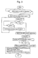
- Figure 3 shows the organization chart of the program first mode of execution.
- Figure 4 shows the flowchart of a variant of this first mode of execution.
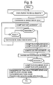
- FIG. 5 shows the flowchart of the second mode of execution.
- the installation shown schematically in the figure 1 comprises a winding tube T on which comes wind up a VR roller shutter and in which is mounted an EU drive unit for tube drive T in rotation.
- This EU training unit includes a single-phase asynchronous motor M ( Figure 2) and a control intelligence consisting of a logical unit ULT treatment ( Figure 2).
- Motor M is powered in single-phase low voltage by a three-wire cable marked BT, while the ULT is connected by a cable to two TBT wires to a PC control point equipped with a Up contact and a Down contact.
- ULT and its interfaces are mounted in a control box BC associated with engine M.
- FIG 2 we distinguish the winding tube T in which is mounted the motor M, more precisely a gearmotor whose output shaft drives a wheel drive R fixed at a point S to the tube winding T.
- a device for counting of the number of laps and fractions of laps carried out by the winding tube is of the well known optoelectronic type. he consists essentially of a C encoder disc rotated by the winding tube T and a CD photocell connected to the ULT. The number of laps and fractions of laps completed by the winding tube is a representative value of the moving the shutter.
- the ULT includes a ⁇ P processor, an H clock consisting of an initializable real-time counter, a RAM type memory MT1 for memorizing a first direction of rotation time, a memory MT2 of RAM type for storing a second time direction of rotation and an EEPROM type MI memory for memorizing the inversion of the Ascent orders and Descent.
- an IS interface for the application of the supply voltage to the motor M so corresponding to the direction of rotation determined by the ULT.
- time is measured put by the roller shutter to make a movement significant up and down and we compare these times, the shortest time corresponding to the descent and the longest time to climb.
- the organization chart of the corresponding program is shown in Figure 3.
- the processor compares the first sense time with the second sense time and then confronts the result of this comparison with the climb order he received.
- the first sense time is greater at second sense time, it means that the sense of rotation 1 ordered by the ULT corresponds to a winding and that the action performed conforms to the order received by the ULT.
- the automation retains its initial assignment: on a climb order, the engine turns in its first sense therefore, in his second for a descent. This assignment is permanently stored in MI memory reversal of orders. The MI memory is consulted by the intelligence of automation before obeying a next order.
- the first sense time is less than second sense time it means that action carried out is contrary to the order received by the ULT and the latter then affects a climb order the second direction and a descending order the first direction.
- this significant displacement could be moving the roller shutter between a high stop and a low stop, more particularly between a high stop corresponds to a winding complete and a low stop corresponding to a complete rolling shutter sequence.
- the significant displacement is therefore equal to the dynamic working of the roller shutter.
- the organization chart of program of this variant is shown in figure 4.
- Automation which understands that the order is a climb order, orders a movement in direction 1. This movement is interrupted when the roller shutter meets a stop. Automation then initializes the clock and orders the engine to reverse its direction of rotation and therefore to rotate in the meaning 2.
- the movement is interrupted when the roller shutter again meets a stop.
- the time counted by the clock is saved in MT2 memory as that TIME SENS 2 and the automation orders the motor to turn in the other direction, i.e. direction 1.
- the clock is reset.
- the automation compares TIME SENS 1 and TIME SENS 2 and confronts the difference with the order received, as in the main execution mode.
- An advantage of this variant is that it allows recognition of upper and lower stops by memorizing the corresponding counter positions.
- Another advantage of this variant is that some the mass of the roller shutter, which influences the amplitude of the displacement to be considered as significant, the device is in conditions optimum operation.
- the automation resets the counter again of displacement and orders the motor to turn in the other direction, that is to say in the second direction.
- the processor then compares the stored values in MT1 and MT2 and confronts the difference with the order given.
- direction 1 corresponds to a winding and direction 2 to a sequence and action performed, in the example considered, corresponds to the order given by the user.
- Automation affects sense 1 to one ascending order and direction 2 to descending order.
- direction 1 corresponds to an unfolding of the store and the action performed does not match the order given by the user.
- the automation then affects the direction 2 to a rise order and direction 1 to an order descent.
- this assignment is stored in the INVERSION OF ORDERS memory which will be consulted by the automation upon receipt of everything ascending or descending order.
- the quantity representative of the speed of rotation of the engine can be obtained in any other way, by example using a tachometer device.
Landscapes
- Engineering & Computer Science (AREA)
- Structural Engineering (AREA)
- Architecture (AREA)
- Civil Engineering (AREA)
- Power Engineering (AREA)
- Operating, Guiding And Securing Of Roll- Type Closing Members (AREA)
- Power-Operated Mechanisms For Wings (AREA)
- Blinds (AREA)
Abstract
Description
Dispositif de commande pour moteur asynchrone à deux sens de rotation utilisé pour l'entraínement d'un store ou volet roulant se déplaçant au moins approximativement verticalement, comprenant un point de commande équipé de contacts Montée et Descente actionnables manuellement et dont l'actionnement assure la rotation du moteur dans le sens désiré, un boítier de commande et d'alimentation, contenant une unité logique de traitement, entre le point de commande et le moteur, des moyens de commutation commandés par l'unité logique de traitement pour l'alimentation de l'un ou l'autre des enroulements du moteur et des moyens d'établissement d'un sens de rotation du moteur correspondant respectivement aux ordres de Montée et Descente.Control device for two-phase asynchronous motor direction of rotation used for driving a blind or rolling shutter moving at least approximately vertically, including a point of control fitted with Up and Down contacts manually actuated and whose actuation ensures rotation of the motor in the desired direction, a housing control and power supply, containing one unit processing logic, between the control point and the motor, switching means controlled by the logical processing unit for supplying either of the motor windings and means for establishing a direction of rotation of the motor corresponding respectively to the climb orders and Descent.
Dans la plupart des installations connues comprenant un store, un volet roulant ou une porte commandée par un moteur asynchrone à deux sens de rotation, les enroulements correspondant à chacun des sens de rotation sont reliés à l'alimentation électrique par l'intermédiaire des contacts du point de commande repérés par des indications "Montée" et "Descente". Il importe donc que lors du câblage, les contacts Montée et Descente soient reliés chacun à l'enroulement dont l'alimentation entraíne une rotation du moteur de façon à provoquer effectivement une montée et une descente du store ou du volet roulant. Or, la montée et la descente du store ou du volet roulant ne dépend pas seulement du repérage correct des conducteurs lors du branchement, mais également de l'orientation du moteur. Ce moteur peut en effet prendre deux positions symétriques, selon qu'il est installé d'un côté ou de l'autre de l'embrasure dans laquelle est monté le store ou le volet roulant, l'effet obtenu étant soit une montée, soit une descente, selon la position du moteur, pour un même sens de rotation de celui-ci. Il est dès lors généralement nécessaire de procéder à une mise sous tension et à un essai avant de procéder au branchement définitif. Une telle manipulation est une perte de temps et par ailleurs elle n'est pas toujours facilement possible, compte tenu de l'accès parfois très difficile au moteur.In most known installations comprising a blind, a shutter or a door controlled by a asynchronous motor with two directions of rotation, windings corresponding to each of the directions of rotation are connected to the power supply by through the control point contacts marked with "Up" and "Down" indications. he It is therefore important that when wiring, the contacts Mounted and Descent are each connected to the winding of which the power supply rotates the motor so to actually cause a rise and fall of the blind or roller shutter. However, the rise and fall of the blind or roller shutter does not only depend on the correct identification of the conductors during connection, but also the orientation of the engine. This engine can indeed take two symmetrical positions, depending that it is installed on either side of the opening in which the blind or the roller shutter, the effect obtained being either a rise, either a descent, depending on the position of the engine, for a same direction of rotation of it. It is therefore generally necessary to carry out voltage and a test before connecting final. Such manipulation is a loss of time and moreover it is not always easily possible, given access sometimes very difficult on the engine.
Le brevet FR 2 671 129 du demandeur décrit un dispositif de commande comportant, entre le point de commande et le moteur, un boítier de commande et d'alimentation contenant une unité logique de traitement dans laquelle est mémorisé un programme d'inversion de sens de rotation du moteur. La mise en oeuvre de ce programme d'inversion est assurée au point de commande par un contact supplémentaire dont l'activation, en même temps que le contact Stop, entraíne l'enregistrement, par l'intelligence de l'automatisme, de l'inversion de la relation ordre/commande. Afin que ce contact supplémentaire ne soit pas actionné par inadvertance il est caché derrière un cache, facilement ouvrable, du boítier du point de commande. Ce contact supplémentaire n'est en outre pas destiné à être actionné par l'utilisateur mais par un homme du métier, c'est-à-dire l'installateur. Or la présence d'un homme du métier lors de la mise sous tension est contraignante, car elle correspond fréquemment à un retour sur le chantier. En effet, cet homme du métier aura bien souvent installé sa motorisation un certain temps avant que la basse tension soit disponible pour d'éventuels tests.Applicant's patent FR 2,671,129 describes a control device comprising, between the point of control and the engine, a control unit and supply unit containing a logical unit of processing in which a program is stored reversing the direction of rotation of the motor. Setting work of this reversal program is assured to the point order by an additional contact including activation, at the same time as the Stop contact, leads to the recording, by the intelligence of automatism, of the inversion of the relation order / order. So that this additional contact does not either not activated inadvertently it is hidden behind a cover, easily openable, of the housing command point. This additional contact is only besides not intended to be operated by the user but by a person skilled in the art, that is to say the installer. The presence of a person skilled in the art during power-up is binding, because it frequently corresponds to a return to the construction site. Indeed, this skilled person will have often installed its motorization a certain time before that low voltage is available for possible tests.
La présente invention a pour but de réaliser un dispositif de commande capable de s'auto-configurer, c'est-à-dire un dispositif de commande capable d'apprendre quel est le sens de rotation du moteur correspondant à l'ordre donné par l'utilisateur, cet apprentissage ne devant pas nécessiter l'intervention d'un homme du métier.The object of the present invention is to provide a control device capable of self-configuration, i.e. a control device capable learn the direction of rotation of the motor corresponding to the order given by the user, this learning not to require intervention of a person skilled in the art.
Le dispositif de commande selon l'invention est caractérisé en ce que les moyens d'établissement d'un sens de rotation du moteur comprennent des moyens de reconnaissance du sens de déplacement du store ou volet roulant par la mesure d'une grandeur représentative de la vitesse de rotation du moteur et, dans l'unité logique de traitement, une mémoire de type EEPROM pour l'enregistrement de l'ordre de sens de rotation à donner au moteur en réponse à un ordre émanant d'un point de commande et un processeur programmé pour comparer le sens de déplacement reconnu avec l'ordre émanant du point de commande et pour inverser, si nécessaire, le sens de rotation enregistré pour cet ordre.The control device according to the invention is characterized in that the means for establishing a direction of motor rotation include means for recognition of the direction of movement of the blind or shutter rolling by measuring a quantity representative of the engine speed and, in the unit processing logic, an EEPROM type memory for recording the order of direction of rotation at give to the engine in response to an order from a control point and a processor programmed to compare the recognized direction of movement with the order from the control point and to reverse, if necessary, the direction of rotation recorded for this order.
Ainsi, lors de la première mise sous tension de l'installation, il suffit à l'utilisateur de donner un ordre quelconque, de montée ou de descente, pour que le moteur du dispositif de commande réponde correctement à l'ordre donné.So when the power is turned on for the first time installation, the user only has to give a any order, ascent or descent, so that the controller motor responds correctly to the order given.
L'invention utilise le fait que le moteur fournit un effort plus grand à l'enroulement qu'au déroulement et que par conséquent tourne moins vite à l'enroulement qu'au déroulement.The invention uses the fact that the engine provides a greater effort in winding than in unwinding and that consequently turns more slowly at the winding that in progress.
La grandeur représentative de la vitesse de rotation du moteur peut être, par exemple, le temps mis par le store ou volet roulant pour effectuer un déplacement significatif ou la mesure du déplacement du store ou volet roulant pendant un temps significatif. Dans ces deux modes d'exécution les moyens de mise en oeuvre sont simples.The quantity representative of the speed of rotation of the motor can be, for example, the time taken by the blind or roller shutter for moving significant or the measurement of the movement of the blind or roller shutter for a significant time. In these two modes of execution the means of implementation are simple.
Ces deux modes d'exécution seront décrits ci-après, à titre d'exemple, en relation avec le dessin annexé.These two modes of execution will be described below, at as an example, in relation to the attached drawing.
La figure 1 est une vue très schématique d'un volet roulant et de son dispositif de commande.Figure 1 is a very schematic view of a shutter and its control device.
La figure 2 représente le tube d'enroulement avec son moteur d'entraínement et l'unité logique de traitement.Figure 2 shows the winding tube with its drive motor and logic processing unit.
La figure 3 représente l'organigramme du programme du premier mode d'exécution.Figure 3 shows the organization chart of the program first mode of execution.
La figure 4 représente l'organigramme d'une variante de ce premier mode d'exécution. Figure 4 shows the flowchart of a variant of this first mode of execution.
La figure 5 représente l'organigramme du second mode d'exécution.Figure 5 shows the flowchart of the second mode of execution.
L'installation représentée schématiquement à la figure 1 comprend un tube d'enroulement T sur lequel vient s'enrouler un volet roulant VR et dans lequel est monté une unité d'entraínement UE pour l'entraínement du tube T en rotation. Cette unité d'entraínement UE comprend un moteur asynchrone monophasé M (figure 2) et une intelligence de commande constituée d'une unité logique de traitement ULT (figure 2). Le moteur M est alimenté en basse tension monophasée par un câble de trois fils repéré BT, tandis que l'ULT est relié par un câble à deux fils TBT à un point de commande PC équipé d'un contact de Montée et d'un contact de Descente. L'ULT et ses interfaces sont montées dans un boítier de commande BC associé au moteur M.The installation shown schematically in the figure 1 comprises a winding tube T on which comes wind up a VR roller shutter and in which is mounted an EU drive unit for tube drive T in rotation. This EU training unit includes a single-phase asynchronous motor M (Figure 2) and a control intelligence consisting of a logical unit ULT treatment (Figure 2). Motor M is powered in single-phase low voltage by a three-wire cable marked BT, while the ULT is connected by a cable to two TBT wires to a PC control point equipped with a Up contact and a Down contact. ULT and its interfaces are mounted in a control box BC associated with engine M.
A la figure 2 on distingue le tube d'enroulement T dans lequel est monté le moteur M, plus précisément un motoréducteur dont l'arbre de sortie entraíne une roue d'entraínement R fixée en un point S au tube d'enroulement T. A l'extrémité du tube d'enroulement représentée est en outre monté un dispositif de comptage du nombre de tours et fractions de tour effectués par le tube d'enroulement. Ce dispositif de comptage est de type optoélectronique bien connu. Il est constitué essentiellement d'un disque codeur C entraíné en rotation par le tube d'enroulement T et d'une cellule photoélectrique CD reliée à l'ULT. Le nombre de tours et fractions de tour effectués par le tube d'enroulement est une valeur représentative du déplacement du volet roulant.In Figure 2 we distinguish the winding tube T in which is mounted the motor M, more precisely a gearmotor whose output shaft drives a wheel drive R fixed at a point S to the tube winding T. At the end of the winding tube shown is further mounted a device for counting of the number of laps and fractions of laps carried out by the winding tube. This device counting is of the well known optoelectronic type. he consists essentially of a C encoder disc rotated by the winding tube T and a CD photocell connected to the ULT. The number of laps and fractions of laps completed by the winding tube is a representative value of the moving the shutter.
L'ULT comporte un processeur µP, une horloge H constituée d'un compteur de temps réel initialisable, une mémoire MT1 de type RAM pour la mémorisation d'un temps de premier sens de rotation, une mémoire MT2 de type RAM pour la mémorisation d'un temps de deuxième sens de rotation et une mémoire MI de type EEPROM pour la mémorisation de l'inversion des ordres Montée et Descente. Entre l'ULT et le moteur M est en outre disposée une interface IS pour l'application de la tension d'alimentation au moteur M de manière correspondant au sens de rotation déterminé par l'ULT.The ULT includes a µP processor, an H clock consisting of an initializable real-time counter, a RAM type memory MT1 for memorizing a first direction of rotation time, a memory MT2 of RAM type for storing a second time direction of rotation and an EEPROM type MI memory for memorizing the inversion of the Ascent orders and Descent. Between the ULT and the engine M is further an IS interface for the application of the supply voltage to the motor M so corresponding to the direction of rotation determined by the ULT.
Le schéma de la figure 2 est valable pour le premier mode d'exécution et sa variante, qui ne diffèrent l'un de l'autre que par la programmation du processeur.The diagram in Figure 2 is valid for the first mode of execution and its variant, which do not differ one on the other than by programming the processor.
Selon le premier mode d'exécution, on mesure le temps mis par le volet roulant pour effectuer un déplacement significatif en montée et en descente et l'on compare ces temps, le temps le plus court correspondant à la descente et le temps le plus long à la montée. L'organigramme du programme correspondant est représenté la figure 3.According to the first embodiment, time is measured put by the roller shutter to make a movement significant up and down and we compare these times, the shortest time corresponding to the descent and the longest time to climb. The organization chart of the corresponding program is shown in Figure 3.
Cet organigramme sera parcouru à l'aide d'un exemple.
Supposons que l'utilisateur donne un ordre de montée. A
la réception de cet ordre, l'ULT ordonne un mouvement
dans le sens 1 et initialise l'horloge H. Supposons
tout d'abord que le volet roulant a effectué un
déplacement significatif déterminé, correspondant en
l'occurrence à un tour du tube d'enroulement T, sans
rencontrer de butée. Le déplacement s'interrompt alors
et l'état du compteur de temps horloge est sauvegardé
dans la mémoire MT1 qui mémorise le temps premier sens.
Le processeur initialise à nouveau l'horloge et
ordonne au moteur de tourner dans l'autre sens, c'est-à-dire
dans le deuxième sens. Après avoir effectué à
nouveau le déplacement significatif, le volet roulant
s'arrête et l'état du compteur de temps horloge est à
nouveau sauvegardé, cette fois dans la mémoire MT2 qui
mémorise le temps deuxième sens.This flowchart will be explored using an example.
Suppose that the user gives a climb order. AT
upon receipt of this order, the ULT orders a movement
in
Le processeur compare le temps premier sens avec le temps deuxième sens, puis confronte le résultat de cette comparaison avec l'ordre de montée qu'il a reçu. Les machines asynchrones ne tournant pas à la même vitesse selon qu'elles sont motrices ou génératrices, le temps mis par le moteur pour enrouler le volet roulant est plus grand que le temps mis par le moteur pour dérouler le volet roulant qui entraíne alors le moteur.The processor compares the first sense time with the second sense time and then confronts the result of this comparison with the climb order he received. Asynchronous machines not running at the same speed depending on whether they are driving or generating, the time taken by the motor to wind the shutter rolling is greater than the time taken by the motor to unwind the roller shutter which then drives the engine.
Par conséquent, si le temps premier sens est supérieur
au temps deuxième sens, cela signifie que le sens de
rotation 1 ordonné par l'ULT correspond à un
enroulement et que l'action effectuée est conforme à
l'ordre reçu par l'ULT. L'automatisme conserve son
affectation initiale : sur un ordre de montée, le
moteur tourne dans son premier sens conséquent, dans
son deuxième pour une descente. Cette affectation est
stockée de façon permanente dans la mémoire MI
inversion des ordres. La mémoire MI est consultée par
l'intelligence de l'automatisme avant d'obéir à un
prochain ordre.Therefore, if the first sense time is greater
at second sense time, it means that the sense of
Si par contre le temps premier sens est inférieur au temps deuxième sens, cela signifie que l'action effectuée est contraire à l'ordre reçu par l'ULT et cette dernière affecte alors un ordre de montée le deuxième sens et un ordre de descente le premier sens.If, on the other hand, the first sense time is less than second sense time it means that action carried out is contrary to the order received by the ULT and the latter then affects a climb order the second direction and a descending order the first direction.
Dans l'organigramme de la figure 3, si le volet roulant rencontre une butée avant d'avoir effectué le déplacement significatif, le sens de rotation du moteur est alors inversé et le temps mis pour effectué le déplacement significatif est mesuré tout d'abord dans le deuxième sens, puis dans le premier sens.In the flow diagram of Figure 3, if the roller shutter meets a stop before performing the significant displacement, the direction of rotation of the motor is then inverted and the time taken to complete the significant displacement is measured first in the second direction, then the first direction.
Au lieu que le déplacement significatif corresponde à un certain nombres de tours du tube d'enroulement, un tour dans l'exemple décrit, ce déplacement significatif pouvait être le déplacement du volet roulant entre une butée haute et une butée basse, plus particulièrement entre une butée haute correspond à un enroulement complet et une butée basse correspondant à un déroulement complet du volet roulant. Dans ce cas, le déplacement significatif est donc égal à la dynamique de travail du volet roulant. L'organigramme du programme de cette variante est représenté à la figure 4.Instead of the significant displacement corresponding to a certain number of turns of the winding tube, a turn in the example described, this significant displacement could be moving the roller shutter between a high stop and a low stop, more particularly between a high stop corresponds to a winding complete and a low stop corresponding to a complete rolling shutter sequence. In this case, the significant displacement is therefore equal to the dynamic working of the roller shutter. The organization chart of program of this variant is shown in figure 4.
Supposons que l'utilisateur donne un ordre de montée au
point de commande. L'automatisme, qui comprend que
l'ordre est un ordre de montée, ordonne un mouvement
dans le sens 1. Ce mouvement s'interrompt lorsque le
volet roulant rencontre une butée. L'automatisme
initialise alors l'horloge et ordonne au moteur
d'inverser son sens de rotation et donc de tourner dans
le sens 2.Suppose that the user gives a climb order to
command point. Automation, which understands that
the order is a climb order, orders a movement
in
Le mouvement s'interrompt lorsque le volet roulant
rencontre à nouveau une butée. Le temps compté par
l'horloge est sauvegardé dans la mémoire MT2 en tant
que TEMPS SENS 2 et l'automatisme ordonne au moteur de
tourner dans l'autre sens, c'est-à-dire le sens 1.
Simultanément, l'horloge est ré-initialisée.The movement is interrupted when the roller shutter
again meets a stop. The time counted by
the clock is saved in MT2 memory as
that
Le mouvement du volet roulant est à nouveau interrompu
lorsque ce dernier rencontre à nouveau une butée et le
temps mesuré dans l'horloge est sauvegardé dans la
mémoire MT1 en tant que TEMPS SENS 1.The movement of the roller shutter is again interrupted
when the latter again encounters a stop and the
time measured in the clock is saved in the
memory MT1 as
L'automatisme compare les TEMPS SENS 1 et TEMPS SENS 2
et confronte la différence avec l'ordre reçu, comme
dans le mode d'exécution principal.The automation compares
Un avantage de cette variante est qu'elle permet une reconnaissance des butées haute et basse en mémorisant les positions de compteur correspondantes.An advantage of this variant is that it allows recognition of upper and lower stops by memorizing the corresponding counter positions.
Un autre avantage de cette variante est que quelque soit la masse du volet roulant, qui influence l'amplitude du déplacement à considérer comme significatif, le dispositif est dans des conditions optimum d'opération. Another advantage of this variant is that some the mass of the roller shutter, which influences the amplitude of the displacement to be considered as significant, the device is in conditions optimum operation.
Au lieu de mesurer le temps mis par le volet roulant pour parcourir une distance significative, on peut inversement mesurer la distance parcourue par le volet roulant dans un intervalle de temps déterminé et fixe. A cet effet il est possible d'utiliser les mêmes moyens que ceux représentés à la figure 2. L'horloge servira à mesurer le temps fixe et les mémoires MTl et MT2 serviront à sauvegarder les déplacements dans un premier sens et dans un second sens. Les impulsions émises par le codeur DC sont comptées par un compteur incrémental de déplacements élémentaires CI pour la mesure de l'espace parcouru par le volet roulant.Instead of measuring the time taken by the roller shutter to cover a significant distance, we can conversely measure the distance traveled by the flap rolling in a fixed and fixed time interval. For this purpose it is possible to use the same means than those shown in Figure 2. The clock will be used to measure the fixed time and the memories MTl and MT2 will be used to save trips in a first sense and in a second sense. The impulses emitted by the DC encoder are counted by a counter incremental of elementary displacements CI for the measurement of the space traveled by the roller shutter.
L'organigramme du programme d'exploration est représenté à la figure 5.The exploration program flowchart is shown in Figure 5.
Supposons, comme dans les cas précédents, que
l'utilisateur, lors de la mise sous tension de
l'installation, donne un ordre de montée au point de
commande. L'automatisme, qui comprend que l'ordre est
un ordre de montée, ordonne un mouvement dans le sens 1
et initialise le compteur de déplacement.Suppose, as in the previous cases, that
user when powering up
the installation, gives an order to climb to the point of
ordered. Automation, which understands that order is
an ascent order, orders a movement in
Si après l'écoulement du temps fixe, cinq secondes dans l'exemple considéré, le volet roulant n'a pas rencontré de butée, le mouvement est interrompu et l'état du compteur de déplacement est sauvegardé dans la mémoire MT1. If after the fixed time has elapsed, five seconds in the example considered, the roller shutter did not meet the movement is interrupted and the state of the displacement counter is saved in memory MT1.
Ensuite, l'automatisme initialise à nouveau le compteur de déplacement et ordonne au moteur de tourner dans l'autre sens, c'est-à-dire dans le deuxième sens.Then, the automation resets the counter again of displacement and orders the motor to turn in the other direction, that is to say in the second direction.
Au bout de cinq secondes le mouvement s'interrompt et l'état du compteur de déplacement est sauvegardé dans la mémoire MT2.After five seconds the movement stops and the status of the displacement counter is saved in MT2 memory.
Le processeur compare ensuite les valeurs mémorisée dans MT1 et MT2 et confronte la différence avec l'ordre donné.The processor then compares the stored values in MT1 and MT2 and confronts the difference with the order given.
Si la distance parcourue dans le sens 1 est inférieure
à la distance parcourue dans le sens 2, le sens 1
correspond à un enroulement et le sens 2 à un
déroulement et l'action effectuée, dans l'exemple
considéré, correspond à l'ordre donné par
l'utilisateur. L'automatisme affecte le sens 1 à un
ordre de montée et le sens 2 à un ordre de descente.If the distance traveled in
Si par contre la distance parcourue dans le sens 1 est
supérieure à la distance parcourue dans le sens 2 cela
signifie que le sens 1 correspond à un déroulement du
store et que l'action effectuée ne correspond à l'ordre
donné par l'utilisateur. L'automatisme affecte alors le
sens 2 à un ordre de montée et le sens 1 à un ordre de
descente. Comme précédemment cette affectation est
stockée dans la mémoire INVERSION DES ORDRES qui sera
consultée par l'automatisme à la réception de tout
ordre de montée ou de descente. If, however, the distance traveled in
La grandeur représentative de la vitesse de rotation du moteur peut être obtenue de toute autre manière, par exemple au moyen d'un dispositif tachymétrique.The quantity representative of the speed of rotation of the engine can be obtained in any other way, by example using a tachometer device.
Claims (7)
Applications Claiming Priority (2)
| Application Number | Priority Date | Filing Date | Title |
|---|---|---|---|
| FR9611857A FR2754117B1 (en) | 1996-09-30 | 1996-09-30 | CONTROL DEVICE FOR AN ASYNCHRONOUS BLIND MOTOR OR ROLLER SHUTTER |
| FR9611857 | 1996-09-30 |
Publications (2)
| Publication Number | Publication Date |
|---|---|
| EP0833435A1 true EP0833435A1 (en) | 1998-04-01 |
| EP0833435B1 EP0833435B1 (en) | 2003-03-12 |
Family
ID=9496167
Family Applications (1)
| Application Number | Title | Priority Date | Filing Date |
|---|---|---|---|
| EP97810702A Expired - Lifetime EP0833435B1 (en) | 1996-09-30 | 1997-09-24 | Control device for asynchronous motor driving a blind or a roller shutter |
Country Status (7)
| Country | Link |
|---|---|
| US (1) | US5847525A (en) |
| EP (1) | EP0833435B1 (en) |
| JP (1) | JPH10115163A (en) |
| AT (1) | ATE234531T1 (en) |
| DE (1) | DE69719655T2 (en) |
| ES (1) | ES2115581T1 (en) |
| FR (1) | FR2754117B1 (en) |
Cited By (16)
| Publication number | Priority date | Publication date | Assignee | Title |
|---|---|---|---|---|
| EP0997605A1 (en) * | 1998-10-29 | 2000-05-03 | DEPRAT Jean S.A. | Method and device for controlling one or more apparatuses, especially a bi-directionnaly rotatable roller shutter drum |
| FR2785431A1 (en) * | 1998-10-29 | 2000-05-05 | Deprat Jean Sa | Method of operation of bi-directional roller door has remote control actuating receiver in roller cylinder |
| AU719830B3 (en) * | 1999-09-24 | 2000-05-18 | Jolly Motor International S.P.A. | Electronic control system for roller blinds and shutters |
| EP1069277A2 (en) * | 1999-07-14 | 2001-01-17 | WAREMA Renkhoff GmbH | Sun protecting arrangement with automatic blind control and possibility of manual intervention |
| FR2832451A1 (en) | 2001-11-22 | 2003-05-23 | Somfy | Solar blind variable start position motor control with control unit/motor installation installed driving blind movement between two end positions and resetting slant position correct setting following movement end. |
| FR2846487A1 (en) * | 2002-10-29 | 2004-04-30 | Alain Durand | Control unit for skylight motor, comprises a microprocessor, thyristor or transistor type switching, a phase sequence detector, mechanically driven limit switches and an asynchronous three phase motor |
| EP1758224A1 (en) * | 2005-08-09 | 2007-02-28 | Adolf Tedsen GmbH & Co. KG | Device for associating a command signal to a direction of rotation of an electric motor for a movable barrier |
| FR2900515A1 (en) * | 2006-04-26 | 2007-11-02 | Bubendorff Sa | ASYNCHRONOUS MOTOR FOR TRAINING BUILDING CLOSURE SYSTEM |
| EP2015156A1 (en) | 2007-07-09 | 2009-01-14 | Somfy SAS | Operating procedure for a home automation installation and home automation installation for its implementation |
| FR2932212A1 (en) * | 2008-06-09 | 2009-12-11 | Bubendorff | CLOSURE DEVICE WITH A REPLIABLE OR ROLLABLE APRON OR STORAGE AND ELECTRIC DRIVE MOTOR |
| WO2012007448A1 (en) | 2010-07-13 | 2012-01-19 | Somfy Sas | Operating method for a device including an electromechanical actuator controlling a movable closure or blackout element for an opening in a building |
| EP2725182A1 (en) | 2012-10-29 | 2014-04-30 | Somfy SAS | Operating method of an actuator for operating a mobile element of a home-automation device and actuator operating according to said method |
| EP3121366A1 (en) * | 2015-07-24 | 2017-01-25 | Somfy SAS | Detection method for the moving direction of a concealing screen |
| EP3121365A1 (en) * | 2015-07-24 | 2017-01-25 | Somfy SAS | Detection method for the moving direction of a concealing screen |
| CN106703673A (en) * | 2016-12-02 | 2017-05-24 | 苏州市职业大学 | Roller shutter door control device |
| US9752081B2 (en) | 2009-07-23 | 2017-09-05 | Ceramatec, Inc. | Method of producing coupled radical products from biomass |
Families Citing this family (28)
| Publication number | Priority date | Publication date | Assignee | Title |
|---|---|---|---|---|
| US6299115B1 (en) * | 1998-06-22 | 2001-10-09 | Hunter Douglas Inc. | Remote control operating system and support structure for a retractable covering for an architectural opening |
| TW392783U (en) * | 1998-08-27 | 2000-06-01 | Hu Yu Min | Electric curtain with learning ability |
| FR2794253B1 (en) * | 1999-05-26 | 2001-08-17 | Deprat Jean Sa | METHOD AND DEVICE FOR CONTROLLING THE OPERATION OF ONE OR MORE BI-DIRECTIONALLY MOBILE ORGANS, AND ASSEMBLY CONSISTING OF A BI-DIRECTIONALLY MOVING MEMBER, SUCH AS A ROLLER SHUTTER, AND SUCH A CONTROL DEVICE |
| JP3559950B2 (en) * | 1998-11-18 | 2004-09-02 | 三和シヤッター工業株式会社 | Architectural electric switchgear |
| US20020175276A1 (en) * | 2001-02-06 | 2002-11-28 | Smith Alan Dane | Method and apparatus for determining a position of a movable barrier |
| CA2362958C (en) | 1999-02-17 | 2007-10-16 | The Chamberlain Group, Inc. | Method and apparatus determining position of a movable barrier |
| ITMI20000738A1 (en) | 2000-04-06 | 2001-10-06 | Paolo Astengo | CONTROL DEVICE WITH THREE-PHASE ELECTRIC MOTOR FOR ROLLING-UP ELEMENTS |
| KR100378872B1 (en) * | 2000-08-14 | 2003-04-07 | (주)동광금속 | Apparatus for shutting the sunlight inside two glass and window established it |
| DE10293394D2 (en) * | 2001-07-26 | 2004-07-01 | Hoermann Kg Antriebstechnik | Building or enclosure closure device and drive device and control device therefor |
| FR2833362B1 (en) * | 2001-12-10 | 2004-02-20 | Somfy | END OF STROKE LEARNING METHOD AND DEVICE FOR IMPLEMENTING THE METHOD |
| KR20020033684A (en) * | 2002-03-15 | 2002-05-07 | 주식회사 유니온서포트 | Curtain |
| US6843301B2 (en) * | 2002-09-09 | 2005-01-18 | Dometic Corporation | Awning roller with internal motor |
| KR20040049500A (en) * | 2002-12-06 | 2004-06-12 | 박선은 | Auto blinder type display assembly |
| FR2858996B1 (en) * | 2003-08-18 | 2005-10-14 | Somfy | METHOD OF INITIALIZING A SHUTTER |
| FR2859026B1 (en) * | 2003-08-19 | 2005-10-14 | Somfy | METHOD FOR INITIALIZING A MOTORIZED ROLLING SHUTTER |
| US20050072532A1 (en) * | 2003-10-01 | 2005-04-07 | Toby Holden | Self-powered motorized window awning |
| US7389806B2 (en) | 2005-02-24 | 2008-06-24 | Lawrence Kates | Motorized window shade system |
| US20060232234A1 (en) * | 2005-04-01 | 2006-10-19 | Newman Robert C Jr | Motorized roller tube system having dual-mode operation |
| US20060232233A1 (en) | 2005-04-01 | 2006-10-19 | Adams Jason O | Drive assembly for a motorized roller tube system |
| US7525265B2 (en) * | 2005-04-20 | 2009-04-28 | The Chamberlain Group, Inc. | Drive motor reversal for a barrier operator or the like |
| FR2902582B1 (en) * | 2006-06-15 | 2008-09-12 | Fp2X Groupement D Interet Econ | DEVICE FOR CONTROLLING A MOTOR WITH TWO DIRECTION OF ROTATION |
| AU2009100649B4 (en) * | 2009-03-17 | 2010-04-01 | Automatic Technology (Australia) Pty Ltd | Door operator circuit board |
| JP5124889B2 (en) * | 2010-10-22 | 2013-01-23 | シナノケンシ株式会社 | Mobile device |
| US9047758B2 (en) | 2013-03-14 | 2015-06-02 | Dometic Corporation | Solar powered energy module |
| CA2870983A1 (en) | 2014-11-06 | 2016-05-06 | Etapa Window Fashions Inc | Motor retrofitted on roll-up blind cords |
| US10863846B2 (en) | 2015-10-02 | 2020-12-15 | Axis Labs Inc. | External motor drive system for window covering system with continuous cord loop |
| CA3000108A1 (en) | 2015-10-02 | 2017-04-06 | Axis Labs Inc. | External motor drive system for window covering system with continuous cord loop |
| US11840886B2 (en) | 2021-05-12 | 2023-12-12 | Ryse Inc. | External motor drive system adjusting for creep in window covering system with continuous cord loop |
Citations (2)
| Publication number | Priority date | Publication date | Assignee | Title |
|---|---|---|---|---|
| EP0439422A1 (en) * | 1990-01-26 | 1991-07-31 | Somfy | Safety mechanism for motorised roller shutters |
| FR2671129A1 (en) * | 1990-12-28 | 1992-07-03 | Sompy | DEVICE FOR CONTROLLING A BLIND MOTOR OR THE LIKE WITH TWO DIRECTIONS OF ROTATION. |
Family Cites Families (8)
| Publication number | Priority date | Publication date | Assignee | Title |
|---|---|---|---|---|
| FR2573551B1 (en) * | 1984-11-16 | 1987-02-06 | Somfy | CONTROL DEVICE FOR ROLLING SHUTTER OR THE LIKE WITH ADJUSTABLE BLADES |
| US4712104A (en) * | 1985-04-19 | 1987-12-08 | Kuron Kabushiki Kaisha | Remote control blind system |
| SE500651C2 (en) * | 1989-01-20 | 1994-08-01 | Ambient Energy Design | Device for controlling the drive motor of window blinds or awnings |
| US5170108A (en) * | 1991-01-31 | 1992-12-08 | Daylighting, Inc. | Motion control method and apparatus for motorized window blinds and and the like |
| FR2692686B1 (en) * | 1992-06-18 | 1997-03-21 | Simu | DIMENSIONED DEVICE FOR CONTROLLING A DRIVING MEMBER OF AN OCCULTATION ELEMENT. |
| US5444339A (en) * | 1993-06-11 | 1995-08-22 | Harmonic Design, Inc. | Mini-blind actuator |
| US5532560A (en) * | 1994-11-08 | 1996-07-02 | Sun Dial Industries, Inc. | Photosensitive automatic blind controller |
| US5642022A (en) * | 1995-12-01 | 1997-06-24 | Msa Aircraft Interior Products, Inc. | Aircraft window shade speed regulation control system |
-
1996
- 1996-09-30 FR FR9611857A patent/FR2754117B1/en not_active Expired - Lifetime
-
1997
- 1997-09-05 US US08/924,780 patent/US5847525A/en not_active Expired - Lifetime
- 1997-09-24 ES ES97810702T patent/ES2115581T1/en active Pending
- 1997-09-24 AT AT97810702T patent/ATE234531T1/en not_active IP Right Cessation
- 1997-09-24 EP EP97810702A patent/EP0833435B1/en not_active Expired - Lifetime
- 1997-09-24 DE DE69719655T patent/DE69719655T2/en not_active Expired - Lifetime
- 1997-09-29 JP JP9263476A patent/JPH10115163A/en not_active Withdrawn
Patent Citations (2)
| Publication number | Priority date | Publication date | Assignee | Title |
|---|---|---|---|---|
| EP0439422A1 (en) * | 1990-01-26 | 1991-07-31 | Somfy | Safety mechanism for motorised roller shutters |
| FR2671129A1 (en) * | 1990-12-28 | 1992-07-03 | Sompy | DEVICE FOR CONTROLLING A BLIND MOTOR OR THE LIKE WITH TWO DIRECTIONS OF ROTATION. |
Cited By (27)
| Publication number | Priority date | Publication date | Assignee | Title |
|---|---|---|---|---|
| FR2785431A1 (en) * | 1998-10-29 | 2000-05-05 | Deprat Jean Sa | Method of operation of bi-directional roller door has remote control actuating receiver in roller cylinder |
| EP0997605A1 (en) * | 1998-10-29 | 2000-05-03 | DEPRAT Jean S.A. | Method and device for controlling one or more apparatuses, especially a bi-directionnaly rotatable roller shutter drum |
| EP1069277A3 (en) * | 1999-07-14 | 2003-06-18 | WAREMA Renkhoff GmbH | Sun protecting arrangement with automatic blind control and possibility of manual intervention |
| EP1069277A2 (en) * | 1999-07-14 | 2001-01-17 | WAREMA Renkhoff GmbH | Sun protecting arrangement with automatic blind control and possibility of manual intervention |
| AU719830B3 (en) * | 1999-09-24 | 2000-05-18 | Jolly Motor International S.P.A. | Electronic control system for roller blinds and shutters |
| AU720228B3 (en) * | 1999-09-24 | 2000-05-25 | Jolly Motor International S.P.A. | Electronic control system for roller blinds and shutters |
| WO2003044312A1 (en) * | 2001-11-22 | 2003-05-30 | Somfy S.A.S. | Method for matching the command issued of the direction of an electric motor in a closure installation or the like such as a roller shutter |
| FR2832451A1 (en) | 2001-11-22 | 2003-05-23 | Somfy | Solar blind variable start position motor control with control unit/motor installation installed driving blind movement between two end positions and resetting slant position correct setting following movement end. |
| FR2846487A1 (en) * | 2002-10-29 | 2004-04-30 | Alain Durand | Control unit for skylight motor, comprises a microprocessor, thyristor or transistor type switching, a phase sequence detector, mechanically driven limit switches and an asynchronous three phase motor |
| EP1758224A1 (en) * | 2005-08-09 | 2007-02-28 | Adolf Tedsen GmbH & Co. KG | Device for associating a command signal to a direction of rotation of an electric motor for a movable barrier |
| US8125176B2 (en) | 2006-04-26 | 2012-02-28 | Bubendorff | Motorized system for closing a building |
| FR2900515A1 (en) * | 2006-04-26 | 2007-11-02 | Bubendorff Sa | ASYNCHRONOUS MOTOR FOR TRAINING BUILDING CLOSURE SYSTEM |
| WO2007125251A1 (en) * | 2006-04-26 | 2007-11-08 | BUBENDORFF, Société Anonyme | Motorized system for closing a building |
| AU2007245509B2 (en) * | 2006-04-26 | 2012-04-12 | Bubendorff (Societe Anonyme) | Motorized system for closing a building |
| EP2015156A1 (en) | 2007-07-09 | 2009-01-14 | Somfy SAS | Operating procedure for a home automation installation and home automation installation for its implementation |
| EP2133505A2 (en) | 2008-06-09 | 2009-12-16 | Bubendorff | Closing device with a shutter or a folding or rolling blind powered by an electric motor |
| FR2932212A1 (en) * | 2008-06-09 | 2009-12-11 | Bubendorff | CLOSURE DEVICE WITH A REPLIABLE OR ROLLABLE APRON OR STORAGE AND ELECTRIC DRIVE MOTOR |
| EP2133505A3 (en) * | 2008-06-09 | 2014-01-22 | Bubendorff | Closing device with a shutter or a folding or rolling blind powered by an electric motor |
| US9752081B2 (en) | 2009-07-23 | 2017-09-05 | Ceramatec, Inc. | Method of producing coupled radical products from biomass |
| WO2012007448A1 (en) | 2010-07-13 | 2012-01-19 | Somfy Sas | Operating method for a device including an electromechanical actuator controlling a movable closure or blackout element for an opening in a building |
| EP2725182A1 (en) | 2012-10-29 | 2014-04-30 | Somfy SAS | Operating method of an actuator for operating a mobile element of a home-automation device and actuator operating according to said method |
| FR2997434A1 (en) * | 2012-10-29 | 2014-05-02 | Somfy Sas | METHOD FOR OPERATING AN ACTUATOR FOR MANEUVERING A MOBILE ELEMENT OF DOMOTIC EQUIPMENT AND ACTUATOR OPERATING ACCORDING TO THIS METHOD. |
| EP3121366A1 (en) * | 2015-07-24 | 2017-01-25 | Somfy SAS | Detection method for the moving direction of a concealing screen |
| EP3121365A1 (en) * | 2015-07-24 | 2017-01-25 | Somfy SAS | Detection method for the moving direction of a concealing screen |
| FR3039193A1 (en) * | 2015-07-24 | 2017-01-27 | Somfy Sas | METHOD FOR DETECTING THE DIRECTION OF DISPLACEMENT OF AN OCCULT SCREEN |
| FR3039192A1 (en) * | 2015-07-24 | 2017-01-27 | Somfy Sas | METHOD FOR DETECTING THE DIRECTION OF DISPLACEMENT OF AN OCCULT SCREEN |
| CN106703673A (en) * | 2016-12-02 | 2017-05-24 | 苏州市职业大学 | Roller shutter door control device |
Also Published As
| Publication number | Publication date |
|---|---|
| DE69719655T2 (en) | 2003-12-24 |
| ES2115581T1 (en) | 1998-07-01 |
| DE69719655D1 (en) | 2003-04-17 |
| FR2754117A1 (en) | 1998-04-03 |
| EP0833435B1 (en) | 2003-03-12 |
| JPH10115163A (en) | 1998-05-06 |
| US5847525A (en) | 1998-12-08 |
| FR2754117B1 (en) | 1998-11-27 |
| ATE234531T1 (en) | 2003-03-15 |
Similar Documents
| Publication | Publication Date | Title |
|---|---|---|
| EP0833435B1 (en) | Control device for asynchronous motor driving a blind or a roller shutter | |
| EP0439422B1 (en) | Safety mechanism for motorised roller shutters | |
| EP0784146B1 (en) | Motorised closure or solar protection installation | |
| EP0426577B1 (en) | Method and device for moving a shade element to adjustable stable positions and installation applying such | |
| EP1510649B1 (en) | Method of initialising a roller blind | |
| EP1508844B1 (en) | Method for initialising a motorized roller shutter | |
| FR2511423A1 (en) | AUTOMATIC DOOR ACTUATION DEVICE | |
| EP3172394B1 (en) | Method of controlling a blind drive, drive system with such method and blind with such drive | |
| EP3433446B1 (en) | Methods for configuring and controlling the operation of a motorised drive device for a home automation unit, and associated unit and motorised drive device | |
| EP0967360A1 (en) | Control device of a roller shutter driving motor | |
| FR3032475A1 (en) | ||
| EP1367471A1 (en) | Method of teaching limit switches for an roller blind actuator | |
| FR2691746A1 (en) | Device generating signals characteristic of the movement of a closure means. | |
| EP1497702A2 (en) | Method of determining an open position for a roller blind | |
| FR2833362A1 (en) | END-OF-STROKE LEARNING METHOD AND DEVICE FOR IMPLEMENTING THE METHOD | |
| FR2657646A1 (en) | Safety device for motorised roller shutter | |
| FR2626118A1 (en) | DEVICE FOR MONITORING A CONTINUOUS CURRENT MOTOR, PARTICULARLY FOR CONTROLLING OPENINGS ON MOTOR VEHICLES | |
| EP3303752B1 (en) | Method for configuring a motorised drive device for a home automation unit, and associated unit and motorised drive device | |
| FR2832451A1 (en) | Solar blind variable start position motor control with control unit/motor installation installed driving blind movement between two end positions and resetting slant position correct setting following movement end. | |
| EP0502773A2 (en) | Motor control device, in particular for driving elevator doors | |
| EP1122404B1 (en) | Movement control for a closing device which rolls on a motor driven roller, and device for implementing such a control | |
| FR2740824A1 (en) | Electrical motor actuated rolling shutter | |
| EP1996984B1 (en) | Method for controlling a roller shutter avoiding too much load on an obstacle | |
| FR2803621A1 (en) | Control system for roller shutters, comprises during initial open/shut programming means to command shutters at any determined time to take up an intermediate position from any previous position | |
| EP1441100A1 (en) | Method for automatic closing of a pivoting wing, automatic closing mechanism and closing installation or sun-protection installation incorporating such a mechanism |
Legal Events
| Date | Code | Title | Description |
|---|---|---|---|
| PUAI | Public reference made under article 153(3) epc to a published international application that has entered the european phase |
Free format text: ORIGINAL CODE: 0009012 |
|
| AK | Designated contracting states |
Kind code of ref document: A1 Designated state(s): AT BE CH DE ES GB IT LI NL SE |
|
| REG | Reference to a national code |
Ref country code: ES Ref legal event code: BA2A Ref document number: 2115581 Country of ref document: ES Kind code of ref document: T1 |
|
| 17P | Request for examination filed |
Effective date: 19980919 |
|
| AKX | Designation fees paid |
Free format text: AT BE CH DE ES GB IT LI NL SE |
|
| RBV | Designated contracting states (corrected) |
Designated state(s): AT BE CH DE ES GB IT LI NL SE |
|
| GRAH | Despatch of communication of intention to grant a patent |
Free format text: ORIGINAL CODE: EPIDOS IGRA |
|
| GRAH | Despatch of communication of intention to grant a patent |
Free format text: ORIGINAL CODE: EPIDOS IGRA |
|
| GRAA | (expected) grant |
Free format text: ORIGINAL CODE: 0009210 |
|
| AK | Designated contracting states |
Designated state(s): AT BE CH DE ES GB IT LI NL SE |
|
| PG25 | Lapsed in a contracting state [announced via postgrant information from national office to epo] |
Ref country code: NL Free format text: LAPSE BECAUSE OF FAILURE TO SUBMIT A TRANSLATION OF THE DESCRIPTION OR TO PAY THE FEE WITHIN THE PRESCRIBED TIME-LIMIT Effective date: 20030312 Ref country code: IT Free format text: LAPSE BECAUSE OF FAILURE TO SUBMIT A TRANSLATION OF THE DESCRIPTION OR TO PAY THE FEE WITHIN THE PRESCRIBED TIME-LIMIT;WARNING: LAPSES OF ITALIAN PATENTS WITH EFFECTIVE DATE BEFORE 2007 MAY HAVE OCCURRED AT ANY TIME BEFORE 2007. THE CORRECT EFFECTIVE DATE MAY BE DIFFERENT FROM THE ONE RECORDED. Effective date: 20030312 Ref country code: GB Free format text: LAPSE BECAUSE OF FAILURE TO SUBMIT A TRANSLATION OF THE DESCRIPTION OR TO PAY THE FEE WITHIN THE PRESCRIBED TIME-LIMIT Effective date: 20030312 Ref country code: AT Free format text: LAPSE BECAUSE OF FAILURE TO SUBMIT A TRANSLATION OF THE DESCRIPTION OR TO PAY THE FEE WITHIN THE PRESCRIBED TIME-LIMIT Effective date: 20030312 |
|
| REG | Reference to a national code |
Ref country code: GB Ref legal event code: FG4D Free format text: NOT ENGLISH |
|
| REG | Reference to a national code |
Ref country code: CH Ref legal event code: EP |
|
| RAP2 | Party data changed (patent owner data changed or rights of a patent transferred) |
Owner name: SOMFY |
|
| REF | Corresponds to: |
Ref document number: 69719655 Country of ref document: DE Date of ref document: 20030417 Kind code of ref document: P |
|
| PG25 | Lapsed in a contracting state [announced via postgrant information from national office to epo] |
Ref country code: SE Free format text: LAPSE BECAUSE OF FAILURE TO SUBMIT A TRANSLATION OF THE DESCRIPTION OR TO PAY THE FEE WITHIN THE PRESCRIBED TIME-LIMIT Effective date: 20030612 |
|
| NLV1 | Nl: lapsed or annulled due to failure to fulfill the requirements of art. 29p and 29m of the patents act | ||
| GBV | Gb: ep patent (uk) treated as always having been void in accordance with gb section 77(7)/1977 [no translation filed] |
Effective date: 20030312 |
|
| PG25 | Lapsed in a contracting state [announced via postgrant information from national office to epo] |
Ref country code: LI Free format text: LAPSE BECAUSE OF NON-PAYMENT OF DUE FEES Effective date: 20030930 Ref country code: ES Free format text: LAPSE BECAUSE OF FAILURE TO SUBMIT A TRANSLATION OF THE DESCRIPTION OR TO PAY THE FEE WITHIN THE PRESCRIBED TIME-LIMIT Effective date: 20030930 Ref country code: CH Free format text: LAPSE BECAUSE OF NON-PAYMENT OF DUE FEES Effective date: 20030930 Ref country code: BE Free format text: LAPSE BECAUSE OF NON-PAYMENT OF DUE FEES Effective date: 20030930 |
|
| PLBE | No opposition filed within time limit |
Free format text: ORIGINAL CODE: 0009261 |
|
| STAA | Information on the status of an ep patent application or granted ep patent |
Free format text: STATUS: NO OPPOSITION FILED WITHIN TIME LIMIT |
|
| 26N | No opposition filed |
Effective date: 20031215 |
|
| BERE | Be: lapsed |
Owner name: *SOMFY Effective date: 20030930 |
|
| REG | Reference to a national code |
Ref country code: CH Ref legal event code: PL |
|
| PGFP | Annual fee paid to national office [announced via postgrant information from national office to epo] |
Ref country code: DE Payment date: 20130925 Year of fee payment: 17 |
|
| REG | Reference to a national code |
Ref country code: DE Ref legal event code: R119 Ref document number: 69719655 Country of ref document: DE |
|
| PG25 | Lapsed in a contracting state [announced via postgrant information from national office to epo] |
Ref country code: DE Free format text: LAPSE BECAUSE OF NON-PAYMENT OF DUE FEES Effective date: 20150401 |