EP0833233B1 - Dispositif de développement et appareil électrostatographique de formation d'image - Google Patents
Dispositif de développement et appareil électrostatographique de formation d'image Download PDFInfo
- Publication number
- EP0833233B1 EP0833233B1 EP97307616A EP97307616A EP0833233B1 EP 0833233 B1 EP0833233 B1 EP 0833233B1 EP 97307616 A EP97307616 A EP 97307616A EP 97307616 A EP97307616 A EP 97307616A EP 0833233 B1 EP0833233 B1 EP 0833233B1
- Authority
- EP
- European Patent Office
- Prior art keywords
- developing
- engaging portion
- developing cartridge
- main assembly
- developing device
- Prior art date
- Legal status (The legal status is an assumption and is not a legal conclusion. Google has not performed a legal analysis and makes no representation as to the accuracy of the status listed.)
- Expired - Lifetime
Links
Images


Classifications
-
- G—PHYSICS
- G03—PHOTOGRAPHY; CINEMATOGRAPHY; ANALOGOUS TECHNIQUES USING WAVES OTHER THAN OPTICAL WAVES; ELECTROGRAPHY; HOLOGRAPHY
- G03G—ELECTROGRAPHY; ELECTROPHOTOGRAPHY; MAGNETOGRAPHY
- G03G15/00—Apparatus for electrographic processes using a charge pattern
-
- G—PHYSICS
- G03—PHOTOGRAPHY; CINEMATOGRAPHY; ANALOGOUS TECHNIQUES USING WAVES OTHER THAN OPTICAL WAVES; ELECTROGRAPHY; HOLOGRAPHY
- G03G—ELECTROGRAPHY; ELECTROPHOTOGRAPHY; MAGNETOGRAPHY
- G03G15/00—Apparatus for electrographic processes using a charge pattern
- G03G15/06—Apparatus for electrographic processes using a charge pattern for developing
- G03G15/08—Apparatus for electrographic processes using a charge pattern for developing using a solid developer, e.g. powder developer
- G03G15/0896—Arrangements or disposition of the complete developer unit or parts thereof not provided for by groups G03G15/08 - G03G15/0894
-
- G—PHYSICS
- G03—PHOTOGRAPHY; CINEMATOGRAPHY; ANALOGOUS TECHNIQUES USING WAVES OTHER THAN OPTICAL WAVES; ELECTROGRAPHY; HOLOGRAPHY
- G03G—ELECTROGRAPHY; ELECTROPHOTOGRAPHY; MAGNETOGRAPHY
- G03G2215/00—Apparatus for electrophotographic processes
- G03G2215/01—Apparatus for electrophotographic processes for producing multicoloured copies
- G03G2215/0167—Apparatus for electrophotographic processes for producing multicoloured copies single electrographic recording member
- G03G2215/0174—Apparatus for electrophotographic processes for producing multicoloured copies single electrographic recording member plural rotations of recording member to produce multicoloured copy
- G03G2215/0177—Rotating set of developing units
-
- G—PHYSICS
- G03—PHOTOGRAPHY; CINEMATOGRAPHY; ANALOGOUS TECHNIQUES USING WAVES OTHER THAN OPTICAL WAVES; ELECTROGRAPHY; HOLOGRAPHY
- G03G—ELECTROGRAPHY; ELECTROPHOTOGRAPHY; MAGNETOGRAPHY
- G03G2215/00—Apparatus for electrophotographic processes
- G03G2215/08—Details of powder developing device not concerning the development directly
- G03G2215/0855—Materials and manufacturing of the developing device
- G03G2215/0872—Housing of developing device
-
- G—PHYSICS
- G03—PHOTOGRAPHY; CINEMATOGRAPHY; ANALOGOUS TECHNIQUES USING WAVES OTHER THAN OPTICAL WAVES; ELECTROGRAPHY; HOLOGRAPHY
- G03G—ELECTROGRAPHY; ELECTROPHOTOGRAPHY; MAGNETOGRAPHY
- G03G2221/00—Processes not provided for by group G03G2215/00, e.g. cleaning or residual charge elimination
- G03G2221/16—Mechanical means for facilitating the maintenance of the apparatus, e.g. modular arrangements and complete machine concepts
- G03G2221/163—Mechanical means for facilitating the maintenance of the apparatus, e.g. modular arrangements and complete machine concepts for the developer unit
-
- G—PHYSICS
- G03—PHOTOGRAPHY; CINEMATOGRAPHY; ANALOGOUS TECHNIQUES USING WAVES OTHER THAN OPTICAL WAVES; ELECTROGRAPHY; HOLOGRAPHY
- G03G—ELECTROGRAPHY; ELECTROPHOTOGRAPHY; MAGNETOGRAPHY
- G03G2221/00—Processes not provided for by group G03G2215/00, e.g. cleaning or residual charge elimination
- G03G2221/16—Mechanical means for facilitating the maintenance of the apparatus, e.g. modular arrangements and complete machine concepts
- G03G2221/1651—Mechanical means for facilitating the maintenance of the apparatus, e.g. modular arrangements and complete machine concepts for connecting the different parts
-
- G—PHYSICS
- G03—PHOTOGRAPHY; CINEMATOGRAPHY; ANALOGOUS TECHNIQUES USING WAVES OTHER THAN OPTICAL WAVES; ELECTROGRAPHY; HOLOGRAPHY
- G03G—ELECTROGRAPHY; ELECTROPHOTOGRAPHY; MAGNETOGRAPHY
- G03G2221/00—Processes not provided for by group G03G2215/00, e.g. cleaning or residual charge elimination
- G03G2221/16—Mechanical means for facilitating the maintenance of the apparatus, e.g. modular arrangements and complete machine concepts
- G03G2221/18—Cartridge systems
- G03G2221/1815—Cartridge systems for cleaning or developing but not being a process cartridge
Definitions
- the present invention relates to a developing device usable with an electrophotographic image forming apparatus such as an electrophotographic copying machine, printer or the like, and an electrophotographic image forming apparatus using the same.
- the electrophotographic image forming apparatus means an apparatus which forms an image on a recording material using an electrophotographic image forming process. It includes for example an electrophotographic copying machine, an electrophotographic printer (LED printer, laser beam printer), an electrophotographic printer type facsimile machine and an electrophotographic printer type word processor.
- U.S. Patent no 4,947,788 describes a process cartridge having three locating members provided at one end of its body.
- a developing cartridge according to claim 1 as well as an image forming apparatus according to claim 15 and a combination according to claim 17.
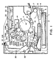
- Figure 1 is an illustration of an entirety of a color laser printer according to an embodiment of the present invention.
- Figure 2 shows an outer appearance of a color laser printer.
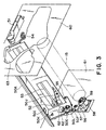
- Figure 3 is a perspective view of a black developing device before it is mounted to a swingable guide portion.
- Figure 4 is a perspective view of a swingable guide portion.
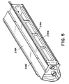
- Figure 5 is a perspective view of a toner accommodating portion of a black developing device.
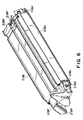
- Figure 6 is a perspective view of an outer appearance of a black developing device.
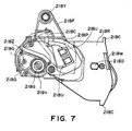
- Figure 7 is a side view of a rear side of a black developing device.
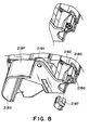
- Figure 8 is a perspective view of a front side of a black developing device.
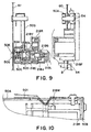
- Figure 9 is a sectional view of a drive transmission structure to a black developing device.
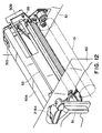
- Figure 10 is an illustration which a state in which black developing device and a swingable guide portion are engaged with each other.
- Figure 11 is a cross-sectional view of a black developing device which is mounted.
- Figure 12 is a perspective view of a black developing device which is mounted to a swingable guide portion and which is contacted to a photosensitive drum.
- Figure 13 is a side view of a front side, in the mounted state, of a black developing device.
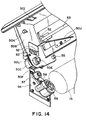
- Figure 14 is an enlarged view of a rear side of a black developing device when it is mounted.
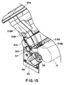
- Figure 15 is an enlarged view of a rear side of a black developing device when it is mounted.
- Figure 16 is a front view of a black developing device as seen from a downstream side in a direction along which it is mounted to the main assembly (it is mounted to the main assembly).
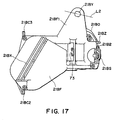
- Figure 17 is a rear view of a black developing device as seen from a downstream side in a direction along which it is mounted to the main assembly (it is mounted to the main assembly).
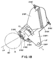
- Figure 18 is a side view of a black developing device which is at a developing position of the main assembly of the apparatus.
- Figure 1 shows a general arrangement of a color laser printer as a color electrophotographic image forming apparatus according to an embodiment of the present invention
- Figure 2 is an outer appearance thereof.
- the color laser printer P of this embodiment comprises an electrophotographic photosensitive member in the form of a drum (photosensitive drum) 15 which rotates at a constant speed, a developing device 21B (for development with black color toner), three color development devices (yellow developing device 20Y for development with yellow color toner, magenta developing device 20M for development with magenta color toner, and a cyan developing device 20C for development with cyan color toner) detachably mountable to a rotatable or revolvable turret.
- a drum photosensitive drum
- developing device 21B for development with black color toner
- three color development devices yellow developing device 20Y for development with yellow color toner
- magenta developing device 20M for development with magenta color toner
- a cyan developing device 20C for development with cyan color toner
- an intermediary transfer member 9 for carrying a superposedly transferred color image and for transferring the image onto a recording material 2 fed from a feeding portion.
- the recording material 2 onto which the color image has been transferred is fed to a fixing portion 25 to fix the color image on the recording material 2, and then the recording material 2 is discharged to a discharging portion 37 at the top of the apparatus by discharging rollers 34, 35, 36.
- the rotatable or revolvable color development devices and the fixed black developing device are detachably mountable relative to the main assembly of the printer, independently from each other.
- a drum unit 13 integrally contains the photosensitive drum 15 and a container 14 of a cleaning device functioning as a holder for the drum 15.
- the drum unit 13 is detachably mountable relative to the main assembly of the printer, and can be easily exchangeable when the lifetime of the photosensitive drum 15 is reached.
- the photosensitive drum 15 of this embodiment comprises an aluminum cylinder having a diameter of 62 mm approx. and an organic photoconductive layer applied to the outside of the aluminum cylinder, and is rotatably supported on the container 14 of the cleaning device which functions also as a housing for the photosensitive drum 15.
- a cleaner blade 16 and a primary charging means 17 are contacted to the outer peripheral surface of the photosensitive drum 15.
- the photosensitive drum 15 receives driving force transmitted from a driving motor (unshown) at one longitudinal end, and is rotated in the counterclockwise direction in accordance with an image forming operation.
- the charging means 17 is a contact charging type charger. An electroconductive roller is contacted to a photosensitive drum 15, and the surface of the photosensitive drum 15 is uniformly charged by application of a voltage to the electroconductive roller.
- the exposure of the photosensitive drum 15 is effected by a scanner 30. More particularly, an image signal is supplied to a laser diode, and the laser diode projects a beam onto a polygonal mirror 31 at a timing corresponding the image signal.
- the polygonal mirror 31 rotates at a high speed by a scanner motor; the beam reflected by the polygonal mirror 31 is selectively projected onto the surface of the photosensitive drum 15 through an imaging lens 32 and a reflection mirror 33, so that charge latent image is formed on the photosensitive drum 15.
- the developing means includes three rotary developing devices 20Y, 20M, 20C for development in yellow, magenta and cyan colors, and one black developing device 21B for development in black color to visualize the electrostatic latent image.
- the black developing device 21B is a fixed developing device at a developing position for effecting the developing operation, except upon the mounting and demounting thereof relative to the main assembly of the apparatus.
- a developing roller 21BS is disposed opposed to the photosensitive drum 15 with a small clearance (approx. 300 ⁇ m) therebetween. It develops an image to visualize a black image with black toner on the photosensitive drum 15.
- the black developing device 21B feeds the toner from the toner accommodating container toward the developing roller 21BA by a feeding mechanism 21BA.
- the toner application blade 21BB press-contacted to the outer periphery of the developing roller 21BS applies the toner in the form of a thin layer on the outer periphery of the developing roller 21BS which is rotating in the indicated clockwise direction, and applies the charge to the toner (triboelectric charge).
- the developing roller 21BS is supplied with a developing bias, so that reverse development (jumping development) corresponding to the electrostatic latent image on the photosensitive drum 15 is effected to form a toner image on the surface of the drum.
- the toner capacity of the black developing device 21B is enough to print 15000 pages (A4, 5% print) which is larger than twice that of the toner capacity of Y, M, C developing devices, in consideration of the toner consumption corresponding to the nature of the documents or image patterns printed by users.
- the position of the black developing device 21B is, as shown in Figure 1, is between the projection position where the photosensitive drum 15 is exposed to the beam from the laser scanner and a development position where the photosensitive drum 15 is subjected to a developing operation by the Y, M, C developing devices.
- the laser scanner is disposed above the developing devices.
- the toner which might leak when the Y, M, C developing devices are revolved, is prevented from scattering to the optical parts such as a laser scanner. Therefore, the polygonal mirror, the lens, the mirror and the like are protected from toner deposition, so that sharp output images can be provided.
- the three revolvable developing devices 20Y, 20M, 20C each contain the toner for 6000 pages (A4, 5 % printing).
- the three revolvable developing devices are detachably mounted on a developing turret 23 which is revolvable about a shaft 22.
- the turret 23 revolves about the shaft 22 while holding the Y, M, C developing devices to place a predetermined developing device to be faced to the photosensitive drum 15.
- the developing roller 20YS of the developing device placed at the development position is disposed opposed to the photosensitive drum 15 with a small clearance (300 ⁇ m approx.), and develops the electrostatic latent image on the photosensitive drum 15 into a visualized image.
- the developing turret 23 rotates for one rotation of the intermediary transfer member 9 so that developing processes are carried out in the order of yellow developing device 20Y, magenta developing device 20M, cyan developing device 20C and the black developing device 21B.
- the yellow revolvable developing device 20Y feeds the toner from the container to the application roller 20YR by a feeding mechanism.
- the application roller 20YR rotating in the clockwise direction and the blade 20YB press-contacted to the outer periphery of the developing roller 20YS
- a thin layer of the toner is applied on the outer periphery of the developing roller 20YS rotating in the clockwise direction in Figure 1, and the toner is triboelectrically charged.
- the developing roller 20YS is supplied with a developing bias so that latent image formed on upper is developed.
- the development is effected through the same process as to the magenta developing device 20M and the cyan developing device 20C.
- the application of the bias to each developing roller and the transmission of the driving force thereto is carried out when the developing device is placed at the developing position.
- the intermediary transfer member 9 superimposedly receives four visualized toner images (Y, M, C, B) from the photosensitive drum 15. It is rotated in the clockwise direction as shown in Figure 1 in synchronism with the outer peripheral speed of the photosensitive drum 15.
- the superimposed toner images on the intermediary transfer member 9 are transferred all together by a transfer roller 10 supplied with a voltage, onto a recording material 2 fed to and nipped between the intermediary transfer member 9 and the transfer roller 10.
- the intermediary transfer member 9 in this embodiment comprises an aluminum cylinder 12 having a diameter of 186 mm and an elastic layer 11 such as intermediate resistance sponge, intermediate resistance rubber or the like on the outer periphery of the aluminum cylinder 12.
- the intermediary transfer member 9 is rotatably supported and is driven by a gear (unshown) fixed thereto.
- the cleaning means functions to remove the toner on the photosensitive drum 15 after the toner image provided by the developing means on the photosensitive drum 15 is transferred onto the intermediary transfer member 9. Thereafter, the removed toner is accumulation in the cleaner container 14. Normally, the amount of the removed toner accumulated in the container 14 does not fill the container 14 before the lifetime of the photosensitive drum is reached. Accordingly, normally the cleaner container 14 is exchanged integrally and simultaneously with the lifetime-end exchange of the photosensitive drum 15.
- the feeding portion functions to feed the recording material 2 into the image formation station. It comprises a cassette 1 for accommodating a plurality of recording materials 2, a pick-up roller 3, a feeding roller 4, a retarding roller 5 for preventing double feeding, a feeding guide 6 and a registration roller 8.
- the feeding roller 3 Upon image formation, the feeding roller 3 is rotated in accordance with the image forming operation to feed the recording materials 2 from the cassette 1 one by one.
- the recording material 2 separated and fed out, is guided by a guide 6, and introduced to the registration roller 8 by the feeding roller 7.
- the registration roller 8 rotates and stops at a predetermined sequence to feed the recording material 2 in synchronism with the transfer process.
- the transfer portion is provided with a swingable transfer roller 10.
- the transfer roller 10 comprises a metal shaft wrapped with an intermediate resistance foamed elastic member and a driving shaft, and is movable in the vertical direction in Figure 1.
- the transfer roller 10 While the four color toner images are formed on the intermediary transfer member 9, that is, while the intermediary transfer member 9 is rotated a plurality of turns, the transfer roller 10 is at a lower position as shown in Figure 1, and is separated from an intermediary transfer member 9 so that toner image is not disturbed.
- the transfer roller 10 is urged toward an upper position indicated by chain lines in Figure 1 at a predetermined pressure toward the intermediary transfer member 9 at predetermined timing for transferring the color image onto the recording material 2. Simultaneously therewith, the transfer roller 10 is supplied with a bias voltage so as to transfer the toner image onto the recording material 2 from the intermediary transfer member 9.
- the recording material 2 nipped between the intermediary transfer member 9 and the transfer roller 10, is advanced at a predetermined speed to the left in Figure 1 during the transfer process, and is fed to a fixing device.
- the fixing station 25 functions to fix the toner image on the recording material.
- the fixing portion 25 comprises a fixing roller 26 for applying heat to the recording material 2, a pressing roller 27 for press-contacting the recording material 2 to the fixing roller 26. These rollers are hollow and contain heaters heater 28, 29. By the rotation of the rollers, the recording material 2 is fed. The recording material 2 carrying the toner image is fed by the fixing roller 26 and the pressing roller 27, and simultaneously therewith, the heat and pressure are applied by which the toner image is fixed on the recording material 2.
- the black developing device being mountable and demountable relative to the main assembly separately from the above-described color developing devices.
- Figure 3 is a perspective view of a black developing device 21B before it is mounted to a swingable guide portion 50.
- Figure 4 is a perspective view of a swingable guide portion.
- Figure 5 is a perspective view of a toner accommodating portion 21BK of a black developing device 21.
- Figure 6 is a perspective view of an outer appearance of a black developing device 21B.
- Figure 7 is a side view of a rear side of the black developing device 21B.
- Figure 8 is a perspective view of a front side of a black developing device 21B.
- Figure 9 is a sectional view of a drive transmission structure to a black developing device 21B.
- Figure 10 is an illustration which a state in which black developing device 21B and a swingable guide portion 50 are engaged with each other.
- Figure 11 is a sectional view when the black developing device is mounted.
- Figure 12 is a perspective view of a black developing device 21B which is mounted to a swingable guide portion 50 and which is contacted to a photosensitive drum 15.
- Figure 13 is a side view of a front side when the black developing device is mounted.
- Figure 14 and Figure 15 are enlarged views of the rear side when the black developing device is mounted to the main assembly of the apparatus.
- Figure 16 is a side view of a leading side (with respect to the direction of mounting of the developing device to the main assembly) when the black developing device 21B is mounted to the main assembly
- Figure 17 is a side view of a trailing side thereof
- Figure 18 is a side view when the black developing device is at the developing position of the main assembly.
- the side of the main assembly which is at the leading side in the black developing device 21B inserting direction is called "rear side”
- the side of the main assembly at the trailing side is called "front side”.
- the black developing device 21B comprises a housing and a developing roller 21BS rotatably mounted thereto, said housing comprising a first housing 21BE including a toner accommodating portion, a holders 21BF, 21BR which are a second housing, at the longitudinal opposite sides thereof.
- the housing is provided with an openable shutter 21BO for protecting the developing roller 21BS, and the black developing device 21B is detachably mountable relative to the swingable guide portion 50 of the main assembly 80 of the apparatus.
- the swingable guide portion 50 has a swingable side plate 50B fixed to the rear side of the swingable guide 50A.
- the swingable guide 50A has a swing hole 50M at the front side, and the rear side swingable side plate 50B has a swing hole 50N.
- the front side plate 60 of the main assembly 80 has a first swing shaft 54 fixed thereto, and the rear side plate 61 has a second swing shaft 55 fixed thereto.
- the first swing shaft 54 and the second swing shaft 55 are engaged with the swing hole 50M and the swing hole 50N, respectively.
- the swingable guide portion 50 is swingable about the swing shafts 54, 55 by the engagement between the swing shaft 54, 55 and the holes 50M, 50N.
- An axis connecting the first swing shaft 54 and the second swing shaft 55 is parallel with a generating line of the photosensitive drum 15, and the swingable guide portion 50 is swingable in a direction perpendicular to the generating line of the photosensitive drum 15.
- the developing roller 21BS of the black developing device 21B mounted to the swingable guide portion 50 becomes parallel with the photosensitive drum 15.
- the swingable guide portion 50 is swung by a rotation lever 51.
- the rotation lever 51 is disposed at the front side 80a ( Figure 2) of the main assembly 80.
- a cam 52 is fixed coaxially to a rotation lever shaft 53 of the rotation lever 51, and rotates in the same phase as the rotation of the rotation lever 51.
- the rotation lever 51 is rotated, the cam 52 rotates, and the outer surface of the cam 52 slides on the swingable guide 50A and the swingable side plate 50B.
- the swingable guide portion 50 swings vertically about the swing shafts 54, 55.
- the rotation lever 51 is rotatable from a horizontal position to a vertical position through approx. 90°, by which the swingable guide portion 50 swings about 10°.
- the rotation lever 51 When the black developing device 21B is inserted into the main assembly 80, the rotation lever 51 is rotated to the horizontal position. At this time, as shown in Figure 3, an insertion opening 63 formed in a front side 80a of the main assembly 80 is completely opened.
- a fresh black developing device 21B When a fresh black developing device 21B is used, the user shakes the black developing device 21B sufficiently, and then, a toner seal (unshown) is pulled out, and loads the black developing device 21B into the main assembly 80. The shaking is to loosen or uncake the toner in the toner accommodating portion 21BK.
- the user After the preparation for the mounting of the black developing device 21B is completed, the user holds the black developing device 21B horizontally, and inserts it into the insertion opening 63.
- the holder 21BR at the black developing device 21B side is provided with a guide rib 21BC which is roughly aligned with the entrance of the swingable guide 50A.
- the guide rib 21BC There is a nominal play of 0.5 - 2 mm between the guide rib 21BC and the entrance of the swingable guide 50A. Therefore, the user roughly aligns the black developing device 21B with the entrance of the swingable guide 50A, and then, pushes it toward rear side, thus smoothly loading it.
- the black developing device 21B is provided with a shutter 21BO for protecting the developing roller 21BS, the shutter 21BO being rotation.
- a shutter openable member 21BP is positioned for rotation about the 21BP1, and is pushed in one direction by a spring (unshown).
- the shutter shaft 21BQ is extended bridging beyond the holder 21BF disposed at the front side 80a, and is supported rotatably on a shaft 21BQ1 coaxial with the developing roller 21BS.
- One supporting portion 21B1 of the shutter 21BO is supported on a shutter opening member 21BP, and the other supporting portion 21B2 is supported by the shutter shaft 21BQ. More particularly, the shutter 21BO is supported at two positions in a cross-sectional plane by the shutter opening member 21BP and the shutter shaft 21BQ. With this state, when the other end portion 21BP1 of the shutter opening member 21BP receives a rotation moment in a direction perpendicular to the generating line of the photosensitive member 15, the shutter opening member 21BP rotates about the shaft 21BP2, so that shutter 21BO rotates smoothly.
- the Figure 7 shows the shutter 21BO when it is at the closing position.
- a stopper 21BZ in the form of a projection in the rotation region of the shutter shaft 21BQ, so that movement of the shutter 21BO in the opening direction is stopped by abutment of the shutter shaft 21BQ to the stopper 21BZ.
- the end of the rotation center shaft 21BQ1 of the shutter shaft 21BQ is inserted in holes 21BL (only front side is shown) formed in the front side holder 21BF and the rear side holder 21BR.
- the holder 21BF at the front side is provided with a hole 21BL in the form of a cut-away portion into which an end of the shutter shaft 21BQ can be press-fitted in a radial direction.
- the end of the shutter shaft 21BQ may be mounted to the side surface of the holder 21BF, using a shutter bearing 21BT.
- the mounting can be carried out in the same direction as the generating line of the photosensitive drum 15, and then, the mounting is further easier.
- the swingable guide portion 50 is provided with a guiding member 50J as shown in Figures 3 and 4 in this embodiment.
- the guiding member 50J is fixed to the swingable guide 50A, and has a wall surface in the form of a non-acute inclined surface.
- the other end portion 21BP1 of the shutter opening member 21BP is abutted to the guiding member 50J.
- the other end portion 21BP3 of the shutter opening member 21BP is moved along the inclined surface formed in the guiding member 50J.
- the shutter opening member 21BP is rotating about 21BP2.
- the angle of the inclined surface portion of the guiding member 50J is desirably not more than 45°, and in this embodiment it is approx. 15°.
- the inclined surface portion of the guiding member 50J is larger than 15° and not more than 45°.
- the side surface of the holder 21BR at the rear side of the black developing device 21B is provided with a drive input engaging portion 21BV and a second positioning hole 21BD functioning as the positioning portion for positioning it relative to the swingable guide portion 50.
- the swingable side plate 50B of the swingable guide portion 50 is provided with a drive transmission engaging portion 50L and a second positioning shaft 50K.
- the driving force transmitting portion 50P comprises a drive transmitting shaft 50E for transmitting the driving force to the driving force input portion 50Q of the black developing device 21B, a drive transmission gear 50F ( Figure 4) for transmitting the rotation force to the drive transmitting shaft 50E, and a drive transmission engaging portion 50L engageable with the driving input engaging portion 21BV provided in the driving force input portion 50Q of the black developing device 21B.
- the driving force input portion 50Q has a driving input gear 21BG for drive transmission of the driving force received by the engaging portion 21BV to the developing roller 21BS.
- a side surface of the transmission shaft 50E is supported by the housing 50C and the housing 50D.
- the drive transmitting shaft 50E has a drive transmission gear 50F fixed thereto, and is urged in one direction by a driving shaft confining spring 50G.
- Drive transmission engaging portion 50L is coaxially and integrally with the drive transmitting shaft 50E. Therefore, the drive transmitting shaft 50E is rotatable coaxially with the drive transmission engaging portion 50L.
- the engaging portion 50L is circular.
- the black developing device 21B is mounted to the main assembly 80 of the apparatus, the circular portion of the engaging portion 50L is engaged with the circular engaging portion 21BV of the developing device 21B.
- the developing device 21B is positioned relative to the main assembly 80 at the rear side.
- the female coupling recess 21BG in the black developing device 21B is supported by developing roller driving bearings 21BI, 21BJ at the opposite ends.
- the developing roller driving bearing 21BI is supported by the driving input engaging portion 21BV formation in the holder 21BR.
- the center of rotation of the female coupling recess 21BG is coaxial with the drive transmission engaging portion 50L.
- the developing roller driving gear 21BG is rotated coaxially with the drive transmission engaging portion 50L.
- the female coupling recess 21BG is provided inside the outer surface of the holder 21BI. This is because the circular portion of the drive transmission engaging portion 50L is engaged therewith.
- the drive transmitting shaft 50E is rotated coaxially with the developing roller driving gear 21BG.
- the developing roller driving gear 21BG drives the developing roller gear 21BH ( Figure 6) to rotate the developing roller 21BS.
- the drive transmission for the black developing device 21B is effected by the coupling engagement, the rotation non-uniformity of the developing roller 21BS can be reduced.
- one end of the drive transmitting shaft 50E has an I-configuration 50EI ( Figure 4) having two cut surfaces.
- an end of the developing roller driving gear 21BG has two walls 21BG1 at symmetrical positions ( Figure 7).
- the shaft end surface 50EL of drive transmitting shaft 50E When the shaft end surface 50EL of drive transmitting shaft 50E is not aligned in phase with the wall 21BGI of the developing roller driving gear 21BG upon the insertion of the black developing device 21B, the shaft end surface 50EL of the drive transmitting shaft 50E interferes the end 21BG1 of the developing roller driving gear 21BG, and therefore, the driving force transmission is not accomplished.
- the drive transmitting shaft 50E is press-contacted in one direction by the confining spring 50G, and therefore, when the drive transmitting shaft 50E rotates a certain extent, the shaft end surface 50EL is engaged between the walls 21BG1 of the driving gear 21BG, so that driving force transmission is enabled.
- the driving input engaging portion 21BV and the second positioning hole 21BD are brought into engagement with the drive transmission engaging portion 50L and the second positioning shaft 50K.
- the rear side of the black developing device 21B is correctly positioned relative to the swingable guide portion 50, and the position thereof is determined in the direction perpendicular to the generating line of the photosensitive drum.
- a regulating member 50I for the black developing device is disposed at the rear side of the swingable guide 50A.
- the regulating member 50I is engaged with an engaging portion 21BW ( Figure 7) formed at the rear side of the black developing device 21B.
- the black developing device 21B is confined in the position thereof in the direction of the generating line of the photosensitive drum.
- the black development regulating member 50I having a resiliency enters the engaging portion 21BW, so that user feels that black developing device 21B is set at the regular position.
- the regulating member 50I prevents the black developing device 21B from offsetting toward the user, when the rotation lever 51 is rotated to swing the black developing device 21B and the swingable guide portion 50.
- the driving unit 56 is provided with a color developing device driving gear 58 connected with the driving source (unshown) and a drum driving gear 59 to transmit the driving force to the developing devices 21M, 21C, 21Y and to the photosensitive drum 15.
- a front side holder 21BF for the black developing device 21B is provided with an elongated hole 21BY functioning as a pivot of the swing of the black developing device 21B, as shown in Figures 7 and 8.
- the elongated hole 21BY functions an engaging portion for engagement with the swing shaft 54 arranged on the side plate 60 at the front side 80a of the main assembly 80.
- the elongated hole 21BY is formed so as to provide a play of 0.5 mm - 1.0 mm approx. to accommodate the variation in the parts.
- the direction of the elongated hole 21BY is substantially the same as a direction 71 of the tangent line of an arcuation 70 having a center at the position of contact between the black developing device 21B (gap roller 21S) and the photosensitive drum 15 and passing through the pivot of the black developing device 21B.
- the distance (radius, or length of the arm) from the contact point between the black developing device 21B and the photosensitive drum 15 to an any portion of the elongated hole 21BY is constant.
- the parallelism deviation between the generating line of the developing roller 21BS and the generating line of the photosensitive drum 15 can be minimized, even if the swing shaft 54 is deviated toward one side of the elongated hole.
- the gap rollers 21S have diameters slightly larger than that of the developing roller 21BS, and therefore, a small gap or play is provided between the developing roller 21BS and the photosensitive drum 15.
- the black developing device 21B is provided exposed at a side surface of the rear side holder 21BR with contacts 21BU1, 21BU2 for applying a bias voltage from the main assembly 80 and for detecting the toner remaining amount.
- the contact 21BU1 is a developing bias contact.
- the developing bias contact 21BU1 is contacted to a main assembly developing bias contact pin 62a ( Figure 14) which will be described hereinafter, which is provided in the main assembly 80, when the black developing device 21B is mounted to the main assembly 80. It receives the developing bias to be applied to the developing roller 21BS from the main assembly 80.
- the contact 21BU2 is a remaining amount detecting contact.
- the remaining amount detecting contact 21BU2 transmits an electric signal to be supplied to a detecting means (unshown) provided in the main assembly 80.
- the value of the electric signal is discriminated by the detecting means (unshown) through the main assembly toner remaining amount detecting pin 62b ( Figure 14) which will be described hereinafter, so that main assembly 80 can detect that toner remaining amount in the toner accommodating portion 21BK is smaller than a predetermined amount.
- the main assembly 80 When the main assembly 80 detects that toner remaining amount in the toner accommodating portion 21BK is smaller than a first predetermined amount, the main assembly 80 notifies the user of the necessity of exchange of the black developing device 21B (for example, flickering of a lamp) (level 1). Thereafter, when the main assembly 80 detects that toner remaining amount in the toner accommodating portion 21BK is smaller than a second predetermined amount, the main assembly 80 of the apparatus is stopped (level 2).
- the electric signal is produced in accordance with the electrostatic capacity between a developing roller 21BS and an antenna (unshown).
- the main assembly contact pins 62a, 62b are provided at the rear side of the main assembly 80.
- the contacts 21BU1, 21BU2 of the black developing device 21B and the main assembly contact pins 62a, 62b are contacted to each other, so that electrical connection is established therebetween.
- the orientation of the rotation lever 51 is vertical, and caps a part of the insertion opening 63 for the black developing device. Therefore, even if the user attempts to pull the black developing device 21B out, it abuts the rotation lever 51 and is not taken out.
- the rotation lever 51 has to be rotated to a horizontal position. Only in such a state, the black developing device 21B can be mounted to or demounted from the main assembly.
- the rotation lever 51 When the black developing device 21B is to be removed from the main assembly 80 of the apparatus, the rotation lever 51 is rotated to a horizontal position ( Figure 3). By pulling the black developing device 21B, it can be removed out.
- the front side holder 21BF of the black developing device 21B is provided with an integrally formed grip portion 21BX which can be hooked by fingers, as shown in Figure 12. Therefore, the user can smoothly pulls the black developing device 21B out using the grip portion 21BX.
- the elongated hole 21BY formed in the front side holder 21BF is engaged with the swing shaft 54. That is, the black developing device 21B is supported by the swing shaft 54 at the front side. Therefore, when the elongated hole 21BY is disengaged from the swing shaft 54, the black developing device 21B lowers by the weight thereof, so that black developing device 21B is supported by the swingable guide 50A.
- the engagement length between the swing shaft 54 and the elongated hole 21BY is long enough. More particularly, as shown in Figure 9, when the black developing device 21B is mounted, and the is disposed at the rear side beyond the end surface B of the opening of the insertion opening 63, the engagement length L between the swing shaft 54 (supporting portion of the main assembly 80) and the elongated hole 21BY (front side pivot of the developing device 21B) is longer than the distance L1 between the wall surface C of the developing device 21B which is closest to the end surface B of the opening and the end surface B of the opening. By doing so, when the elongated hole 21BY is disengaged from the swing shaft 54, the wall surface C of the black developing device is prevented from abutting the member defining the opening of the insertion opening 63.
- Figure 16 is a side view of a leading side of the black developing device with respect to the mounting direction of the black developing device (mounted in the main assembly);
- Figure 17 is a side view of a trailing side of the black developing device (mounted in the main assembly);
- Figure 18 is a side view of the black developing device located at the developing position.
- the angle of the longitudinal direction of the elongated hole 21BY (line L2) is within approx. 5° - 15° relative to the line L3 connecting the center of the female coupling recess 21BG and the center of the hole 21BD.
- the above-described angle is 5° approx.
- the longitudinal direction (direction indicated by the arrow L2 in Figure 18) of the elongated hole 21BY is substantially codirectional with the direction in which the developing roller 21BS is urged toward the peripheral surface of the photosensitive drum 15 (direction indicated by the arrow L4 in Figure 18) (as shown in Figure 18, lines L2, L4 are substantially parallel).
- the black developing cartridge 21B is correctly positioned to the developing position within the range of the elongated hole 21BY, since the developing roller 21BS is movable toward and away from the peripheral surface of the photosensitive drum 15 (directions indicated by the arrow Y in Figure 18).
- Figure 18 designated by 17 is a portion where a grip (unshown) for pulling the toner seal (unshown) has been provided.
- the drive transmission for the black developing cartridge 21B in the foregoing embodiment is summarized as follows:
- the foregoing embodiments are directed to a color image forming apparatus as an example, but the present invention is applicable to a monochromatic image forming apparatus.
- the black development cartridge is taken as an example, the present invention is applicable to a color development cartridge.
- the printer is taken as an example, but the present invention is applicable to a copying machine, facsimile machine or another electrophotographic recording system image forming apparatus.
- the developing device can be properly mounted or demounted by inserting or pulling it along the swingable guide portion of the image forming apparatus. Therefore, in a color image forming apparatus, the black developing device which can accommodate a large amount of toner can be easily mounted or demounted.
- the positioning of the developing cartridge relative to the main assembly of the electrophotographic image forming apparatus can be improved.
Landscapes
- Physics & Mathematics (AREA)
- General Physics & Mathematics (AREA)
- Electrophotography Configuration And Component (AREA)
- Dry Development In Electrophotography (AREA)
Claims (19)
- Cartouche de développement (21B) destinée à développer une image latente formée sur un élément photosensible électrophotographique (15), laquelle cartouche peut être montée de façon amovible par rapport à un ensemble principal (80) d'un appareil électrophographique de formation d'images, ladite cartouche de développement comportant :un corps allongé conçu pour être introduit dans l'ensemble principal (80) dans sa direction longitudinale, ladite direction définissant une extrémité avant et une extrémité arrière dudit corps ;un élément de développement (21BS) pour le développement d'une image latente formée sur l'élément photosensible ;une partie (28BK) de logement de toner destinée à loger du toner devant être utilisé pour développer l'image latente formée sur l'élément photosensible (15) ;une première partie d'engagement (21BD) destinée à réaliser un engagement avec un premier élément de positionnement (50K), situé dans l'ensemble principal, ladite première partie d'engagement (21BD) étant située à ladite extrémité avant de ladite cartouche de développement (21B) ;une seconde partie d'engagement (21BV) destinée à réaliser un engagement avec un second élément de positionnement (50L), situé dans l'ensemble principal, ladite seconde partie d'engagement (21BV) étant située à ladite extrémité avant de ladite cartouche de développement (21B) ;un élément (21BG) de réception de force d'entraínement, situé dans ladite seconde partie d'engagement (21BV), pour recevoir de l'ensemble principal une force d'entraínement destinée à faire tourner ledit élément de développement (21BS) ;une troisième partie d'engagement (21BY) destinée à réaliser un engagement avec un troisième élément de positionnement (54) situé dans l'ensemble principal, ladite troisième partie d'engagement (21BY) étant située à ladite extrémité arrière de ladite cartouche de développement (21B), dans laquelle ladite troisième partie d'engagement (21BY) est située dans une partie extrême libre d'un bras (21BF1) faisant saillie dans une direction croisant ladite direction longitudinale de ladite cartouche de développement (21B).
- Cartouche de développement selon la revendication 1, dans laquelle ladite première partie d'engagement (21BD) présente un évidemment ayant une configuration allongée.
- Cartouche de développement selon la revendication 1 ou la revendication 2, dans laquelle ladite seconde partie d'engagement (21BV) a une configuration circulaire.
- Cartouche de développement selon l'une quelconque des revendications précédentes, dans laquelle ladite troisième partie d'engagement (21BG) présente un évidement ayant une configuration allongée.
- Cartouche de développement selon la revendication 4, dans laquelle un angle formé entre une direction longitudinale de la configuration allongée de ladite troisième partie d'engagement (21BG) et une ligne reliant les centres de ladite première partie d'engagement et de ladite deuxième partie d'engagement est d'environ 5,0° à 15,0°.
- Cartouche de développement selon la revendication 4, comportant en outre une première partie de guidage (21BC) et une seconde partie de guidage (21BC), s'étendant dans la direction longitudinale dudit élément de développement, pour guider ladite cartouche de développement lorsque ladite cartouche de développement est montée sur l'ensemble principal dans la direction longitudinale dudit élément de développement.
- Cartouche de développement selon la revendication 2, dans laquelle la direction longitudinale de la configuration de trou allongé de ladite première partie d'engagement (21BD) est dirigée sensiblement vers ladite deuxième partie d'engagement (21BV).
- Cartouche de développement selon la revendication 3, dans laquelle le diamètre de ladite deuxième partie d'engagement est plus grand que la longueur, mesurée dans la direction longitudinale de la configuration de trou allongé, de ladite première partie d'engagement.
- Cartouche de développement selon la revendication 8, dans laquelle la longueur de ladite première partie d'engagement n'est pas inférieure à environ 9,0 mm, et sa largeur est d'environ 7,0 mm à 9,0 mm, et le diamètre de ladite deuxième partie d'engagement est d'environ 8,0 mm à 10,0 mm.
- Cartouche de développement selon la revendication 4, dans laquelle la longueur de ladite troisième partie d'engagement est d'environ 8,0 mm à 10,0 mm, et sa largeur est d'environ 7,0 mm à 9,0 mm.
- Cartouche de développement selon la revendication 3, dans laquelle ladite première partie d'engagement est disposée de façon à être adjacente à une extrémité longitudinale dudit élément de développement dans une direction croisant la direction longitudinale dudit élément de développement, et ledit second évidement est disposé à une extrémité longitudinale de ladite partie de logement de toner.
- Cartouche de développement selon l'une quelconque des revendications précédentes, comportant en outre un contact (21BU1) de polarisation de développement à nu à ladite première extrémité de ladite cartouche de développement, pour recevoir, de l'ensemble principal, une tension de polarisation de développement devant être appliquée audit élément de développement lorsque ladite cartouche de développement est montée sur l'ensemble principal.
- Cartouche de développement selon la revendication 12, comportant en outre un contact (21BU2) de détection de la quantité restante de toner, à nu, à ladite première extrémité de ladite cartouche de développement, pour permettre à l'ensemble principal de détecter une quantité de toner restante dans ladite partie de logement de toner, ledit contact de détection de quantité restante étant juxtaposé audit contact de polarisation de développement.
- Cartouche de développement selon l'une quelconque des revendications précédentes, comportant en outre un obturateur (21BO) mobile entre une position de recouvrement pour recouvrir une surface dudit élément de développement et une position d'exposition rétractée de ladite position de recouvrement pour exposer une surface dudit élément de développement, et dans laquelle un premier centre de rotation (21BL) d'un premier bras de support (21BQ) destiné à supporter une extrémité longitudinale dudit obturateur et un second centre de rotation (21BT) d'un second bras de support (21BQ) destiné à supporter l'autre extrémité longitudinale dudit obturateur sont situés à des extrémités longitudinales respectives de ladite cartouche de développement.
- Appareil électrophotographique de formation d'images destiné à former une image sur un support d'enregistrement, sur lequel une cartouche de développement peut être montée de façon amovible, ledit appareil comportant :a. un élément d'avance destiné à faire avancer un support d'enregistrement ;b. un élément de transmission de force d'entraínement destiné à transmettre une force d'entraínement ;c. un élément de montage destiné au montage d'une cartouche de développement, laquelle cartouche comprend :un corps allongé conçu pour être introduit dans l'ensemble principal (80) dans sa direction longitudinale, ladite direction définissant une extrémité avant et une extrémité arrière de ladite cartouche ;un élément de développement (21BS) destiné à développer une image latente formée sur l'élément photosensible ;une partie (28BK) de logement de toner destinée à loger des toners devant être utilisés pour. développer l'image latente formée sur l'élément photosensible (15) ;une première partie d'engagement (21BD) destinée à réaliser un engagement avec un premier élément de positionnement (50K), situé dans l'ensemble principal, ladite première partie d'engagement (21BD) étant située à ladite extrémité avant de ladite cartouche de développement (21B) ;une deuxième partie d'engagement (21BV) destinée à réaliser un engagement avec un deuxième élément de positionnement (50L) située dans l'ensemble principal, ladite deuxième partie d'engagement (21BV) étant située à ladite extrémité avant de ladite cartouche de développement (21B) ;un élément (21BG) de réception de force d'entraínement, situé dans ladite deuxième partie d'engagement (21BV), destinée à recevoir de l'ensemble principal une force d'entraínement pour faire tourner ledit élément de développement (21BS) ;une troisième partie d'engagement (21BY) destinée à réaliser un engagement avec un troisième élément de positionnement (54) située dans l'ensemble principal, ladite troisième partie d'engagement (21BY) étant située à ladite extrémité arrière de ladite cartouche de développement (21B), dans lequel ladite troisième partie d'engagement (21BY) est située dans une partie extrême libre d'un bras (21BF1) faisant saillie dans une direction croisant ladite direction d'introduction de ladite cartouche de développement (21B).
- Appareil selon la revendication 15, dans lequel le moyen de montage comprend un élément pivotant (50) de support destiné à supporter ladite cartouche de développement, ledit élément pivotant de support pouvant pivoter autour d'un axe entre une position de développement pour placer ladite cartouche de développement dans une position de travail et une position rétractée en retrait de la position de travail, dans lequel un premier élément de positionnement (50K) et un deuxième élément de positionnement (50L) sont prévus sur ledit élément pivotant de support à un côté arrière dudit élément pivotant de support, et dans lequel un troisième élément de positionnement (54) est disposé sur un prolongement de l'axe.
- Appareil électrophotographique (P) de formation d'images en combinaison avec une cartouche de développateur (21) ; l'appareil électrophotographique (P) de formation d'images comportant :un tambour photosensible (15) ayant un axe longitudinal ;un élément (50) pouvant pivoter autour d'un axe parallèle à l'axe longitudinal du tambour entre une première position pour recevoir la cartouche de développateur et une seconde position dans laquelle la cartouche de développateur est en position "d'utilisation" dans l'appareil ;des premier (50K) et deuxième (50L) éléments de positionnement situés à une extrémité de l'élément pivotant (50) ; etun troisième élément de positionnement (54) associé à l'autre extrémité axiale de l'élément pivotant (50) et placé coaxialement avec l'axe de rotation dudit élément pivotant ;la cartouche de développateur (21) comportant :un corps allongé conçu pour être introduit dans l'appareil de formation d'images dans sa direction longitudinale, ladite direction d'introduction définissant une extrémité avant et une extrémité arrière du corps ;le corps comprenant des premier (21BD) et deuxième (21BG) éléments de positionnement à ladite extrémité avant pour coopérer avec lesdits premier (50K) et deuxième (50L) éléments de positionnement de l'élément pivotant (50) ; etle corps comprenant un troisième élément de positionnement (21BY) à l'extrémité arrière pour coopérer avec le troisième élément de positionnement (54) de l'appareil de formation d'images.
- Combinaison selon la revendication 17, dans laquelle ledit troisième élément de positionnement de l'appareil de formation d'images est situé sur une partie non pivotante dudit appareil.
- Combinaison selon la revendication 17, dans laquelle ledit troisième élément de positionnement de l'appareil de formation d'images est situé sur l'élément pivotant.
Applications Claiming Priority (6)
| Application Number | Priority Date | Filing Date | Title |
|---|---|---|---|
| JP258876/96 | 1996-09-30 | ||
| JP25887696 | 1996-09-30 | ||
| JP25887696 | 1996-09-30 | ||
| JP26173397A JP3416485B2 (ja) | 1996-09-30 | 1997-09-26 | 現像カートリッジ及び電子写真画像形成装置 |
| JP26173397 | 1997-09-26 | ||
| JP261733/97 | 1997-09-26 |
Publications (3)
| Publication Number | Publication Date |
|---|---|
| EP0833233A2 EP0833233A2 (fr) | 1998-04-01 |
| EP0833233A3 EP0833233A3 (fr) | 1999-09-08 |
| EP0833233B1 true EP0833233B1 (fr) | 2002-11-27 |
Family
ID=26543868
Family Applications (1)
| Application Number | Title | Priority Date | Filing Date |
|---|---|---|---|
| EP97307616A Expired - Lifetime EP0833233B1 (fr) | 1996-09-30 | 1997-09-29 | Dispositif de développement et appareil électrostatographique de formation d'image |
Country Status (8)
| Country | Link |
|---|---|
| US (1) | US5995782A (fr) |
| EP (1) | EP0833233B1 (fr) |
| JP (1) | JP3416485B2 (fr) |
| KR (1) | KR100270222B1 (fr) |
| CN (1) | CN1091268C (fr) |
| AU (1) | AU702276B2 (fr) |
| DE (1) | DE69717388T2 (fr) |
| HK (1) | HK1009513A1 (fr) |
Families Citing this family (18)
| Publication number | Priority date | Publication date | Assignee | Title |
|---|---|---|---|---|
| JP3697090B2 (ja) * | 1998-10-26 | 2005-09-21 | キヤノン株式会社 | 電子写真画像形成装置 |
| JP2000250310A (ja) * | 1999-02-26 | 2000-09-14 | Brother Ind Ltd | 画像形成装置、感光体カートリッジ及び現像カートリッジ |
| JP3684209B2 (ja) * | 2002-05-31 | 2005-08-17 | キヤノン株式会社 | カートリッジ及び電子写真画像形成装置 |
| JP2004109438A (ja) * | 2002-09-18 | 2004-04-08 | Canon Inc | 電子写真画像形成装置 |
| US20040184046A1 (en) * | 2003-03-17 | 2004-09-23 | Toshiba Tec Kabushiki Kaisha | Image forming apparatus and image forming method |
| JP4556507B2 (ja) * | 2004-06-17 | 2010-10-06 | 船井電機株式会社 | レーザプリンタ |
| JP2008076634A (ja) | 2006-09-20 | 2008-04-03 | Seiko Epson Corp | ロータリ現像装置およびこれを備えた画像形成装置 |
| JP4148530B2 (ja) * | 2006-12-08 | 2008-09-10 | キヤノン株式会社 | プロセスカートリッジ及び電子写真画像形成装置 |
| JP2009086320A (ja) * | 2007-09-28 | 2009-04-23 | Fujinon Corp | 防振ユニット、撮影ユニット、および撮影装置 |
| JP2012073288A (ja) * | 2010-09-27 | 2012-04-12 | Fuji Xerox Co Ltd | 画像形成装置 |
| SG183169A1 (en) | 2010-12-03 | 2012-09-27 | Ricoh Co Ltd | Powder container, powder supply device and image forming apparatus |
| TWI461863B (zh) | 2011-11-25 | 2014-11-21 | Ricoh Co Ltd | 粉末容器和影像形成設備 |
| KR102002623B1 (ko) | 2012-06-03 | 2019-07-22 | 가부시키가이샤 리코 | 분체 용기 및 화상 형성 장치 |
| US9465317B2 (en) | 2013-02-25 | 2016-10-11 | Ricoh Company, Ltd. | Nozzle insertion member, powder container, and image forming apparatus |
| CN105143991B (zh) | 2013-03-15 | 2019-11-15 | 株式会社理光 | 粉末容器和图像形成设备 |
| US10459398B2 (en) * | 2016-09-30 | 2019-10-29 | Brother Kogyo Kabushiki Kaisha | Developing cartridge having electric contact surface |
| KR20200025336A (ko) | 2018-08-30 | 2020-03-10 | 휴렛-팩커드 디벨롭먼트 컴퍼니, 엘.피. | 토너 충전부의 유입 셔터를 선택적으로 로킹하는 구조 |
| JP2020160273A (ja) * | 2019-03-27 | 2020-10-01 | ブラザー工業株式会社 | 画像形成装置 |
Family Cites Families (8)
| Publication number | Priority date | Publication date | Assignee | Title |
|---|---|---|---|---|
| US4947788A (en) * | 1988-10-17 | 1990-08-14 | Eastman Kodak Company | Development station having toner monitor |
| JP2983310B2 (ja) * | 1991-01-29 | 1999-11-29 | 株式会社リコー | 画像形成装置の回転型現像装置 |
| JP3298728B2 (ja) * | 1993-11-12 | 2002-07-08 | 株式会社リコー | 画像形成装置 |
| JP3044997B2 (ja) * | 1994-02-16 | 2000-05-22 | ブラザー工業株式会社 | 画像形成装置における現像装置 |
| AU1763195A (en) * | 1994-04-26 | 1995-11-23 | Canon Kabushiki Kaisha | Process cartridge and image forming apparatus |
| JP2877728B2 (ja) * | 1994-04-28 | 1999-03-31 | キヤノン株式会社 | プロセスカートリッジ及び画像形成装置 |
| AU3426895A (en) * | 1994-10-17 | 1996-05-02 | Canon Kabushiki Kaisha | Toner container, toner container assembling method, process cartridge, and electrophotographic image forming apparatus |
| JPH0916056A (ja) * | 1995-06-30 | 1997-01-17 | Canon Inc | プロセスカートリッジ及び画像形成装置 |
-
1997
- 1997-09-26 JP JP26173397A patent/JP3416485B2/ja not_active Expired - Fee Related
- 1997-09-29 US US08/939,620 patent/US5995782A/en not_active Expired - Lifetime
- 1997-09-29 DE DE69717388T patent/DE69717388T2/de not_active Expired - Lifetime
- 1997-09-29 EP EP97307616A patent/EP0833233B1/fr not_active Expired - Lifetime
- 1997-09-30 KR KR1019970050211A patent/KR100270222B1/ko not_active IP Right Cessation
- 1997-09-30 AU AU39319/97A patent/AU702276B2/en not_active Ceased
- 1997-09-30 CN CN97122798A patent/CN1091268C/zh not_active Expired - Fee Related
-
1998
- 1998-08-25 HK HK98110209A patent/HK1009513A1/xx not_active IP Right Cessation
Also Published As
| Publication number | Publication date |
|---|---|
| DE69717388T2 (de) | 2003-07-10 |
| CN1091268C (zh) | 2002-09-18 |
| DE69717388D1 (de) | 2003-01-09 |
| JP3416485B2 (ja) | 2003-06-16 |
| AU3931997A (en) | 1998-04-02 |
| JPH10153911A (ja) | 1998-06-09 |
| EP0833233A3 (fr) | 1999-09-08 |
| AU702276B2 (en) | 1999-02-18 |
| KR19980025158A (ko) | 1998-07-06 |
| HK1009513A1 (en) | 1999-06-04 |
| KR100270222B1 (ko) | 2000-10-16 |
| EP0833233A2 (fr) | 1998-04-01 |
| US5995782A (en) | 1999-11-30 |
| CN1182895A (zh) | 1998-05-27 |
Similar Documents
| Publication | Publication Date | Title |
|---|---|---|
| EP0833233B1 (fr) | Dispositif de développement et appareil électrostatographique de formation d'image | |
| US7349649B2 (en) | Process cartridge, positioning mechanism therefor and electrophotographic image forming apparatus | |
| US7835665B2 (en) | Photosensitive unit and image forming apparatus | |
| US7174122B2 (en) | Developer supply container and electrophotographic image forming apparatus | |
| US7155141B2 (en) | Electrophotographic image forming apparatus | |
| JP3869901B2 (ja) | 現像カートリッジ及び電子写真画像形成装置 | |
| EP1403737B1 (fr) | Unité de développement et procédé de montage de son couvercle latéral | |
| US7085516B2 (en) | Process cartridge and electrophotographic image forming apparatus | |
| US7149457B2 (en) | Process cartridge and electrophotographic image forming apparatus | |
| US7158736B2 (en) | Process cartridge having first and second rotatably coupled frames and electrophotographic image forming apparatus mounting such process cartridge | |
| EP1336905B1 (fr) | Montage stable pour unité de traitement et appareil électrophotographique de formation d'images | |
| US7212768B2 (en) | Process cartridge and electrophotographic image forming apparatus | |
| JPH09297443A (ja) | 現像カートリッジ及び電子写真画像形成装置 | |
| JPH09297444A (ja) | 現像カートリッジ及び電子写真画像形成装置 | |
| US20050117934A1 (en) | Process cartridge, mounting method of electrophotographic photosensitive drum and replacing method of the photosensitive drum | |
| EP0833234B1 (fr) | Dispositif de développement et appareil électrostatographique de formation d'image | |
| AU736223B2 (en) | Developing device and electrophotographic image forming apparatus |
Legal Events
| Date | Code | Title | Description |
|---|---|---|---|
| PUAI | Public reference made under article 153(3) epc to a published international application that has entered the european phase |
Free format text: ORIGINAL CODE: 0009012 |
|
| AK | Designated contracting states |
Kind code of ref document: A2 Designated state(s): CH DE FR GB IT LI |
|
| PUAL | Search report despatched |
Free format text: ORIGINAL CODE: 0009013 |
|
| AK | Designated contracting states |
Kind code of ref document: A3 Designated state(s): AT BE CH DE DK ES FI FR GB GR IE IT LI LU MC NL PT SE |
|
| RIC1 | Information provided on ipc code assigned before grant |
Free format text: 6G 03G 21/18 A, 6G 03G 15/08 B |
|
| 17P | Request for examination filed |
Effective date: 20000121 |
|
| AKX | Designation fees paid |
Free format text: CH DE FR GB IT LI |
|
| 17Q | First examination report despatched |
Effective date: 20010523 |
|
| GRAG | Despatch of communication of intention to grant |
Free format text: ORIGINAL CODE: EPIDOS AGRA |
|
| GRAG | Despatch of communication of intention to grant |
Free format text: ORIGINAL CODE: EPIDOS AGRA |
|
| GRAH | Despatch of communication of intention to grant a patent |
Free format text: ORIGINAL CODE: EPIDOS IGRA |
|
| GRAH | Despatch of communication of intention to grant a patent |
Free format text: ORIGINAL CODE: EPIDOS IGRA |
|
| GRAA | (expected) grant |
Free format text: ORIGINAL CODE: 0009210 |
|
| AK | Designated contracting states |
Kind code of ref document: B1 Designated state(s): CH DE FR GB IT LI |
|
| PG25 | Lapsed in a contracting state [announced via postgrant information from national office to epo] |
Ref country code: LI Free format text: LAPSE BECAUSE OF FAILURE TO SUBMIT A TRANSLATION OF THE DESCRIPTION OR TO PAY THE FEE WITHIN THE PRESCRIBED TIME-LIMIT Effective date: 20021127 Ref country code: IT Free format text: LAPSE BECAUSE OF FAILURE TO SUBMIT A TRANSLATION OF THE DESCRIPTION OR TO PAY THE FEE WITHIN THE PRESCRIBED TIME-LIMIT;WARNING: LAPSES OF ITALIAN PATENTS WITH EFFECTIVE DATE BEFORE 2007 MAY HAVE OCCURRED AT ANY TIME BEFORE 2007. THE CORRECT EFFECTIVE DATE MAY BE DIFFERENT FROM THE ONE RECORDED. Effective date: 20021127 Ref country code: CH Free format text: LAPSE BECAUSE OF FAILURE TO SUBMIT A TRANSLATION OF THE DESCRIPTION OR TO PAY THE FEE WITHIN THE PRESCRIBED TIME-LIMIT Effective date: 20021127 |
|
| REG | Reference to a national code |
Ref country code: GB Ref legal event code: FG4D |
|
| REG | Reference to a national code |
Ref country code: CH Ref legal event code: EP |
|
| REF | Corresponds to: |
Ref document number: 69717388 Country of ref document: DE Date of ref document: 20030109 |
|
| REG | Reference to a national code |
Ref country code: CH Ref legal event code: PL |
|
| ET | Fr: translation filed | ||
| PLBE | No opposition filed within time limit |
Free format text: ORIGINAL CODE: 0009261 |
|
| STAA | Information on the status of an ep patent application or granted ep patent |
Free format text: STATUS: NO OPPOSITION FILED WITHIN TIME LIMIT |
|
| 26N | No opposition filed |
Effective date: 20030828 |
|
| REG | Reference to a national code |
Ref country code: FR Ref legal event code: PLFP Year of fee payment: 19 |
|
| PGFP | Annual fee paid to national office [announced via postgrant information from national office to epo] |
Ref country code: GB Payment date: 20150922 Year of fee payment: 19 Ref country code: DE Payment date: 20150930 Year of fee payment: 19 |
|
| PGFP | Annual fee paid to national office [announced via postgrant information from national office to epo] |
Ref country code: FR Payment date: 20150928 Year of fee payment: 19 |
|
| REG | Reference to a national code |
Ref country code: DE Ref legal event code: R119 Ref document number: 69717388 Country of ref document: DE |
|
| GBPC | Gb: european patent ceased through non-payment of renewal fee |
Effective date: 20160929 |
|
| REG | Reference to a national code |
Ref country code: FR Ref legal event code: ST Effective date: 20170531 |
|
| PG25 | Lapsed in a contracting state [announced via postgrant information from national office to epo] |
Ref country code: FR Free format text: LAPSE BECAUSE OF NON-PAYMENT OF DUE FEES Effective date: 20160930 Ref country code: GB Free format text: LAPSE BECAUSE OF NON-PAYMENT OF DUE FEES Effective date: 20160929 Ref country code: DE Free format text: LAPSE BECAUSE OF NON-PAYMENT OF DUE FEES Effective date: 20170401 |