EP0832003B1 - Vorrichtung zum verstellen translatorisch verstellbarer bauteile in kraftfahrzeugen - Google Patents
Vorrichtung zum verstellen translatorisch verstellbarer bauteile in kraftfahrzeugen Download PDFInfo
- Publication number
- EP0832003B1 EP0832003B1 EP96921891A EP96921891A EP0832003B1 EP 0832003 B1 EP0832003 B1 EP 0832003B1 EP 96921891 A EP96921891 A EP 96921891A EP 96921891 A EP96921891 A EP 96921891A EP 0832003 B1 EP0832003 B1 EP 0832003B1
- Authority
- EP
- European Patent Office
- Prior art keywords
- drive device
- drive
- elements
- translationally displaceable
- fastening
- Prior art date
- Legal status (The legal status is an assumption and is not a legal conclusion. Google has not performed a legal analysis and makes no representation as to the accuracy of the status listed.)
- Expired - Lifetime
Links
- 238000013016 damping Methods 0.000 claims description 33
- 238000006073 displacement reaction Methods 0.000 claims 2
- 238000002347 injection Methods 0.000 claims 1
- 239000007924 injection Substances 0.000 claims 1
- 229920001971 elastomer Polymers 0.000 description 14
- 239000005060 rubber Substances 0.000 description 14
- 230000005540 biological transmission Effects 0.000 description 9
- 230000000694 effects Effects 0.000 description 3
- 239000011324 bead Substances 0.000 description 2
- 238000006243 chemical reaction Methods 0.000 description 2
- 230000006378 damage Effects 0.000 description 2
- 238000000034 method Methods 0.000 description 2
- 239000004033 plastic Substances 0.000 description 2
- 238000013461 design Methods 0.000 description 1
- 238000011161 development Methods 0.000 description 1
- 230000006872 improvement Effects 0.000 description 1
- 238000003780 insertion Methods 0.000 description 1
- 230000037431 insertion Effects 0.000 description 1
- 238000009434 installation Methods 0.000 description 1
- 230000010354 integration Effects 0.000 description 1
- 230000002028 premature Effects 0.000 description 1
- 230000008569 process Effects 0.000 description 1
- 230000009467 reduction Effects 0.000 description 1
- 230000002787 reinforcement Effects 0.000 description 1
- 230000008439 repair process Effects 0.000 description 1
- 230000006641 stabilisation Effects 0.000 description 1
- 238000011105 stabilization Methods 0.000 description 1
- 230000003068 static effect Effects 0.000 description 1
- 239000000725 suspension Substances 0.000 description 1
- 238000013519 translation Methods 0.000 description 1
Images
Classifications
-
- E—FIXED CONSTRUCTIONS
- E05—LOCKS; KEYS; WINDOW OR DOOR FITTINGS; SAFES
- E05F—DEVICES FOR MOVING WINGS INTO OPEN OR CLOSED POSITION; CHECKS FOR WINGS; WING FITTINGS NOT OTHERWISE PROVIDED FOR, CONCERNED WITH THE FUNCTIONING OF THE WING
- E05F11/00—Man-operated mechanisms for operating wings, including those which also operate the fastening
- E05F11/38—Man-operated mechanisms for operating wings, including those which also operate the fastening for sliding windows, e.g. vehicle windows, to be opened or closed by vertical movement
- E05F11/48—Man-operated mechanisms for operating wings, including those which also operate the fastening for sliding windows, e.g. vehicle windows, to be opened or closed by vertical movement operated by cords or chains or other flexible elongated pulling elements, e.g. tapes
- E05F11/481—Man-operated mechanisms for operating wings, including those which also operate the fastening for sliding windows, e.g. vehicle windows, to be opened or closed by vertical movement operated by cords or chains or other flexible elongated pulling elements, e.g. tapes for vehicle windows
- E05F11/483—Man-operated mechanisms for operating wings, including those which also operate the fastening for sliding windows, e.g. vehicle windows, to be opened or closed by vertical movement operated by cords or chains or other flexible elongated pulling elements, e.g. tapes for vehicle windows by cables
- E05F11/485—Man-operated mechanisms for operating wings, including those which also operate the fastening for sliding windows, e.g. vehicle windows, to be opened or closed by vertical movement operated by cords or chains or other flexible elongated pulling elements, e.g. tapes for vehicle windows by cables with cable tensioners
-
- B—PERFORMING OPERATIONS; TRANSPORTING
- B60—VEHICLES IN GENERAL
- B60J—WINDOWS, WINDSCREENS, NON-FIXED ROOFS, DOORS, OR SIMILAR DEVICES FOR VEHICLES; REMOVABLE EXTERNAL PROTECTIVE COVERINGS SPECIALLY ADAPTED FOR VEHICLES
- B60J1/00—Windows; Windscreens; Accessories therefor
- B60J1/08—Windows; Windscreens; Accessories therefor arranged at vehicle sides
- B60J1/12—Windows; Windscreens; Accessories therefor arranged at vehicle sides adjustable
- B60J1/16—Windows; Windscreens; Accessories therefor arranged at vehicle sides adjustable slidable
- B60J1/17—Windows; Windscreens; Accessories therefor arranged at vehicle sides adjustable slidable vertically
-
- B—PERFORMING OPERATIONS; TRANSPORTING
- B60—VEHICLES IN GENERAL
- B60N—SEATS SPECIALLY ADAPTED FOR VEHICLES; VEHICLE PASSENGER ACCOMMODATION NOT OTHERWISE PROVIDED FOR
- B60N2/00—Seats specially adapted for vehicles; Arrangement or mounting of seats in vehicles
- B60N2/02—Seats specially adapted for vehicles; Arrangement or mounting of seats in vehicles the seat or part thereof being movable, e.g. adjustable
- B60N2/04—Seats specially adapted for vehicles; Arrangement or mounting of seats in vehicles the seat or part thereof being movable, e.g. adjustable the whole seat being movable
- B60N2/06—Seats specially adapted for vehicles; Arrangement or mounting of seats in vehicles the seat or part thereof being movable, e.g. adjustable the whole seat being movable slidable
- B60N2/067—Seats specially adapted for vehicles; Arrangement or mounting of seats in vehicles the seat or part thereof being movable, e.g. adjustable the whole seat being movable slidable by linear actuators, e.g. linear screw mechanisms
-
- E—FIXED CONSTRUCTIONS
- E05—LOCKS; KEYS; WINDOW OR DOOR FITTINGS; SAFES
- E05F—DEVICES FOR MOVING WINGS INTO OPEN OR CLOSED POSITION; CHECKS FOR WINGS; WING FITTINGS NOT OTHERWISE PROVIDED FOR, CONCERNED WITH THE FUNCTIONING OF THE WING
- E05F15/00—Power-operated mechanisms for wings
- E05F15/60—Power-operated mechanisms for wings using electrical actuators
- E05F15/603—Power-operated mechanisms for wings using electrical actuators using rotary electromotors
- E05F15/665—Power-operated mechanisms for wings using electrical actuators using rotary electromotors for vertically-sliding wings
- E05F15/689—Power-operated mechanisms for wings using electrical actuators using rotary electromotors for vertically-sliding wings specially adapted for vehicle windows
-
- E—FIXED CONSTRUCTIONS
- E05—LOCKS; KEYS; WINDOW OR DOOR FITTINGS; SAFES
- E05F—DEVICES FOR MOVING WINGS INTO OPEN OR CLOSED POSITION; CHECKS FOR WINGS; WING FITTINGS NOT OTHERWISE PROVIDED FOR, CONCERNED WITH THE FUNCTIONING OF THE WING
- E05F11/00—Man-operated mechanisms for operating wings, including those which also operate the fastening
- E05F11/38—Man-operated mechanisms for operating wings, including those which also operate the fastening for sliding windows, e.g. vehicle windows, to be opened or closed by vertical movement
- E05F11/42—Man-operated mechanisms for operating wings, including those which also operate the fastening for sliding windows, e.g. vehicle windows, to be opened or closed by vertical movement operated by rack bars and toothed wheels or other push-pull mechanisms
- E05F11/423—Man-operated mechanisms for operating wings, including those which also operate the fastening for sliding windows, e.g. vehicle windows, to be opened or closed by vertical movement operated by rack bars and toothed wheels or other push-pull mechanisms for vehicle windows
-
- E—FIXED CONSTRUCTIONS
- E05—LOCKS; KEYS; WINDOW OR DOOR FITTINGS; SAFES
- E05F—DEVICES FOR MOVING WINGS INTO OPEN OR CLOSED POSITION; CHECKS FOR WINGS; WING FITTINGS NOT OTHERWISE PROVIDED FOR, CONCERNED WITH THE FUNCTIONING OF THE WING
- E05F11/00—Man-operated mechanisms for operating wings, including those which also operate the fastening
- E05F11/38—Man-operated mechanisms for operating wings, including those which also operate the fastening for sliding windows, e.g. vehicle windows, to be opened or closed by vertical movement
- E05F11/48—Man-operated mechanisms for operating wings, including those which also operate the fastening for sliding windows, e.g. vehicle windows, to be opened or closed by vertical movement operated by cords or chains or other flexible elongated pulling elements, e.g. tapes
- E05F11/481—Man-operated mechanisms for operating wings, including those which also operate the fastening for sliding windows, e.g. vehicle windows, to be opened or closed by vertical movement operated by cords or chains or other flexible elongated pulling elements, e.g. tapes for vehicle windows
- E05F11/483—Man-operated mechanisms for operating wings, including those which also operate the fastening for sliding windows, e.g. vehicle windows, to be opened or closed by vertical movement operated by cords or chains or other flexible elongated pulling elements, e.g. tapes for vehicle windows by cables
- E05F11/486—Man-operated mechanisms for operating wings, including those which also operate the fastening for sliding windows, e.g. vehicle windows, to be opened or closed by vertical movement operated by cords or chains or other flexible elongated pulling elements, e.g. tapes for vehicle windows by cables with one cable connection to the window glass
-
- E—FIXED CONSTRUCTIONS
- E05—LOCKS; KEYS; WINDOW OR DOOR FITTINGS; SAFES
- E05Y—INDEXING SCHEME ASSOCIATED WITH SUBCLASSES E05D AND E05F, RELATING TO CONSTRUCTION ELEMENTS, ELECTRIC CONTROL, POWER SUPPLY, POWER SIGNAL OR TRANSMISSION, USER INTERFACES, MOUNTING OR COUPLING, DETAILS, ACCESSORIES, AUXILIARY OPERATIONS NOT OTHERWISE PROVIDED FOR, APPLICATION THEREOF
- E05Y2201/00—Constructional elements; Accessories therefor
- E05Y2201/40—Motors; Magnets; Springs; Weights; Accessories therefor
- E05Y2201/43—Motors
- E05Y2201/434—Electromotors; Details thereof
-
- E—FIXED CONSTRUCTIONS
- E05—LOCKS; KEYS; WINDOW OR DOOR FITTINGS; SAFES
- E05Y—INDEXING SCHEME ASSOCIATED WITH SUBCLASSES E05D AND E05F, RELATING TO CONSTRUCTION ELEMENTS, ELECTRIC CONTROL, POWER SUPPLY, POWER SIGNAL OR TRANSMISSION, USER INTERFACES, MOUNTING OR COUPLING, DETAILS, ACCESSORIES, AUXILIARY OPERATIONS NOT OTHERWISE PROVIDED FOR, APPLICATION THEREOF
- E05Y2600/00—Mounting or coupling arrangements for elements provided for in this subclass
- E05Y2600/40—Mounting location; Visibility of the elements
- E05Y2600/46—Mounting location; Visibility of the elements in or on the wing
-
- E—FIXED CONSTRUCTIONS
- E05—LOCKS; KEYS; WINDOW OR DOOR FITTINGS; SAFES
- E05Y—INDEXING SCHEME ASSOCIATED WITH SUBCLASSES E05D AND E05F, RELATING TO CONSTRUCTION ELEMENTS, ELECTRIC CONTROL, POWER SUPPLY, POWER SIGNAL OR TRANSMISSION, USER INTERFACES, MOUNTING OR COUPLING, DETAILS, ACCESSORIES, AUXILIARY OPERATIONS NOT OTHERWISE PROVIDED FOR, APPLICATION THEREOF
- E05Y2900/00—Application of doors, windows, wings or fittings thereof
- E05Y2900/50—Application of doors, windows, wings or fittings thereof for vehicles
- E05Y2900/53—Type of wing
- E05Y2900/55—Windows
Definitions
- the invention relates to a device for adjustment Components in motor vehicles that can be adjusted in translation such as window regulators, sunroofs and the like.
- Such a device is known from EP 0 208 237 B1 known. It consists of a combination of a window pane a motor vehicle with a disc driver, which connects the window pane with a guide device and over a rope and pulleys with a fixed one Drive device for translatory adjustment the window pane is connected.
- the connection between the driver and the window pane is by a in the Window arranged through hole and a through the through hole and connected to the driver Pen manufactured.
- For guiding the window pane support and auxiliary wings are provided on the driver from the driver to the surfaces of the window pane extend.
- the lower edge of the window pane lies on elastically deformable elements of the driver to Generate backlash and rattling noises between the Avoid driver and the window pane.
- Devices for adjusting translationally adjustable Components in motor vehicles are usually attached to base plates, Door inner panels or body parts of a motor vehicle screwed, riveted or with guide rails partially welded.
- the attachment of the drive devices on the relevant base part thus requires a certain one, given by the static conditions Number of fasteners in multiple steps attached and when necessary Repairs must be removed again.
- the fastening of the drive devices additional technological at the base parts Process steps, the assembly time and thus additional Cause costs.
- system damping is required during switching operations and take effect when a stop is reached and absorb peak loads or dynamic peak loads dampen.
- This system has been damped so far basically in the interior of the transmission of the drive device, for example in the form of positive damping chambers in the worm wheel of the transmission of the drive device. Between the driver and the worm wheel radial damping rubbers are arranged, which are targeted Energy conversion through flexing depending on Effect torque and thus dynamic load peaks intercept.
- the damping elements arranged within the transmission housing require an additional portion of the gearbox space and thus reduce the effective guide length of worm wheel and driver on the fixed axis or lead to an increase in the external dimensions of the Gearbox and thus the drive device.
- there is bad tooth meshing and to an undesirable axial expansion of the Rubber damper so that premature wear or the Danger of inoperability threatens.
- the Efficiency of the drive device deteriorates.
- the object of the present invention is a drive device for translationally adjustable components in motor vehicles to create an easy assembly and Disassembly allowed with little expenditure of time and a Damping the drive system without negative influences Gear elements enabled.
- This task is accomplished by creating a device for adjusting translationally adjustable components with solved the features of claim 1.
- the solution according to the invention shortens the assembly or Disassembly process for the drive device clearly and requires considerably fewer individual parts for fastening the drive device or its connection to the translationally adjustable component.
- the relocation of the Damping of the drive system outside the gearbox space creates an inexpensive cushioning and a flatter Structure of the drive device, allows a more rigid Ribbing of the worm wheel and an improvement the guide length on the axis as well as an acoustic Decoupling of the drive device from the base part to accommodate the translationally adjustable component or of the translationally adjustable component at one easy assembly of the relevant damping elements.
- the solution according to the invention is both stationary Components of the translationally adjustable component or of a component for receiving the translational component as well as moving components of the translational adjustable component applicable.
- the base part can consist of a stationary or movable one Component of the translationally adjustable component or the device for receiving the translationally adjustable Component exist.
- a stationary component assigns several recesses or passages Inclusion of the axis and fasteners of the drive device and the damping elements.
- a movable component is this over the Drive device compared to the stationary components the component or the device for receiving the component adjustable, has a recess to accommodate the axle on and is via resilient support points connected to the drive device.
- the adjustment device known from EP 0 208 237 B1 differs from the subject of the present invention no drive device, but is with one Power transmission element connected in the form of a rope, so that only appropriately aligned translational forces come into effect. Because there is no torque load can, no pivoting of the driver occurs through the through hole of the window pane Axis due to the reaction forces when turning the drive device in one direction or the other on, but the connection is only for connection of the driver on the window pane.
- the resilient Support of the driver for receiving the lower edge of the window pane only serves to compensate for relative movements between the window pane and the driver, to allow tolerances between the driver and compensate for the window pane.
- An advantageous embodiment of the invention Solution is characterized in that the gear housing the drive device an axially extending Ring collar and several outside the axis of the ring collar and the gear housing arranged radially to each other has spaced fastening and damping elements.
- the fasteners are used to additionally stiffen the system and the devices on the stationary component geometrically to accommodate the fasteners Voted.
- the fasteners can be made of hat or ball bolts consist of those adapted to the diameter of the bolt heads Bores of the stationary component are pluggable and by turning the drive device into radially extending recesses adapted to the diameter of the pin pins can be used, the drive device in the operating position by means of the damping elements opposite can be prevented from twisting.
- a direct connection of the drive device with the movable component of the translationally adjustable Component preferably has the movable component a hole for receiving one with the drive device connected or connectable fastening bolt and at least one, preferably two on both sides of the bore arranged support points for receiving damping elements on.
- This configuration of the solution according to the invention results an advantageous integration of moving component and Drive device arranged together protected can be.
- the drive motor can rotate about its transverse axis, while at the same time the damping elements the window pane and protect the engine from destruction.
- the damping elements At a Arrangement of two preloaded damping elements additional tolerances of the bore to accommodate the with the Drive device connected or connectable mounting bolt balanced.
- a further advantageous embodiment is characterized in that that the output of the drive device as Hollow shaft is designed with positive locking elements such that the drive device on both faces with a pinion or a cable drum to drive the translational adjustable component connectable and therefore universal can be equipped.
- the output of the drive device as Hollow shaft is designed with positive locking elements such that the drive device on both faces with a pinion or a cable drum to drive the translational adjustable component connectable and therefore universal can be equipped.
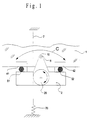
- FIG. 1 shows one Rope window regulator with a window pane 1 on one Drive device 2 is attached, which is part of a preferably driver guided in a disk guide device is and with a rope 7 for translational adjustment the unit from window pane 1 and drive device 2 is connected.
- the rope 7 is on an upper one and lower rope attachment attached, being in the area of provided a rope length compensation 70 lower rope suspension is.
- the connection between window pane 1 and Drive device 2 takes place via a window connection, that of an axis 6 and one in the window pane 1 provided recess 10 for receiving the axis 6 (fastening bolts) consists.
- the drive device 2 is around this disc connection 6, 10 in the direction of arrow C swiveling.
- connection of the drive device 2 with the rope 7 takes place via a cable drum 28 in a known manner Wise.
- Arrangement of a rope window regulator can be the principle of Attachment of the drive device 2 to the window pane 1 also with a cross arm window regulator or a window regulator applied with positive power transmission elements which are fastened in the door body.
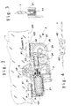
- FIG. 1 Figures 2 to 4 show the detailed arrangement for schematic representation according to FIG. 1.
- the drive device 2 contains a drive motor 21 and a gear 22 that connects to the motor shaft Drive worm 23 and two stepped gear wheels 24, 25 for a two-stage gearbox consisting of one with the Drive worm 23 meshing worm wheel with pinion 24 and there is a gear 25.
- a Form-locking element 29 is an output element (pinion) the axis of the gear 25 can be clipped on, the force and / or positively connected to the rope 7 or a rack, so that when the motor runs clockwise or counterclockwise, the drive unit 2 together with the window pane 1 or is moved downwards. Since the output element on one or other side of the gearbox can be clipped on described device for both a right and can be used for a left side arrangement.
- connection of the window pane 1 with the drive unit 2 takes place via a located on the gear housing Fastening eye 26, via which the drive unit is form-fitting attached in a bore 10 of the window pane 1 becomes.
- the attachment is via an axis 6, the is preferably designed as a plastic bolt, so that the drive unit 2 slightly around the window connection 6, 10 can rotate.
- Damping devices consisting of fastening tabs 41, 42 with rubber molded elements 51, 52 inserted therein.
- the lower edge of the pane is in these fastening tabs 41, 42 100 used so that the support points 101, 102nd the lower pane edge 100 on the molded rubber elements 51, 52 lie on it and therefore according to the geometry and Shore hardness the rubber molded elements 51, 52 the damped rotary movement the drive unit 2 around the window connection 6, 10 limit.
- the window pane lies on the flank of the molded rubber elements 51, 52 always on, so that when slamming the door or in the case of lateral force components, the drive motor 21 cannot rotate about its transverse axis. Protect at the same time the molded rubber elements 51, 52, the window pane 1 and Drive motor 21 when slamming the door from destruction.
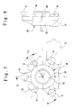
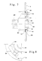
- Figures 5 to 8 is a plan view, one Side view, a longitudinal section and a partial view a drive unit shown with a stationary Component, in particular with a base plate, or a Inner door panel or door module for a power window drive unit can be connected.
- the Gear housing 20 has an annular collar 61, which according to FIG into a precisely fitting passage 30 of a base plate or a door module 3 can be used.
- On axis 60 of the gearbox 20 is either a rope drum or a Pinion for actuating the translationally adjustable Attachable component, while the drive via a Drive motor 21 and a gear 22 according to FIGS. 5 and 6 takes place.
- the gear housing 20 also has damping elements 16, 17, which with damping elements 18, 19 in engagement stand that in the base plate, the inner door panel or door module 3 can be used.
- the drive unit After the drive unit after insertion into the holes or recesses 30, 33, 34 of the base plate, the inner door panel or Door module 3 inserted and rotated into the operating position the drive unit with the damping elements 16 to 19 secured against twists that do not have exceed the prescribed level of damping rate.
- This causes the drive unit to turn under load maximum ⁇ 5 ° around the axis 60, the bias of the Damping elements 16 to 19 and their Shore hardness the desired Determine the twist angle and thus the damping rate.
- the drive unit can be soft in the Retract stops without using a toothed segment window regulator as a translationally adjustable component the center distance is changed.
- the hat bolts or ball bolts 13 to 15 are arranged preferably in beads in the inner door panel, the base plate or the door module, whereby in the recesses of the beads Rubber disks 11, 12 can be used for acoustic decoupling are, so that a transmission of the drive noise the stationary component in question is minimized.
- the drive unit easily from the inside or outside on a base plate, an inner door panel or a door module inserted or be clipped in and contacted. This is an assembly or disassembly possible with little expenditure of time.
- the drive unit can be used either in dry or wet room to be ordered.
- Rubber washers are available with an additional Shore hardness Noise minimization possible.
- the rubber washers or Intermediate layers of rubber 11, 12 decouple the drive unit inexpensive from the inner door panel, the base plate or the door module.
- the angle-of-rotation-limiting rubber elements 18, 19 can in the damping chambers, which are in the inner door panel area inserted, easy to install or be plugged in.
Landscapes
- Engineering & Computer Science (AREA)
- Mechanical Engineering (AREA)
- Aviation & Aerospace Engineering (AREA)
- Transportation (AREA)
- Power-Operated Mechanisms For Wings (AREA)
- Window Of Vehicle (AREA)
- Measurement Of Distances Traversed On The Ground (AREA)
Applications Claiming Priority (3)
| Application Number | Priority Date | Filing Date | Title |
|---|---|---|---|
| DE19525020A DE19525020A1 (de) | 1995-06-28 | 1995-06-28 | Antriebseinrichtung für translatorisch verstellbare Bauteile in Kraftfahrzeugen |
| DE19525020 | 1995-06-28 | ||
| PCT/DE1996/001196 WO1997001454A1 (de) | 1995-06-28 | 1996-06-28 | Vorrichtung zum verstellen translatorisch verstellbarer bauteile in kraftfahrzeugen |
Publications (2)
| Publication Number | Publication Date |
|---|---|
| EP0832003A1 EP0832003A1 (de) | 1998-04-01 |
| EP0832003B1 true EP0832003B1 (de) | 2000-03-22 |
Family
ID=7766411
Family Applications (1)
| Application Number | Title | Priority Date | Filing Date |
|---|---|---|---|
| EP96921891A Expired - Lifetime EP0832003B1 (de) | 1995-06-28 | 1996-06-28 | Vorrichtung zum verstellen translatorisch verstellbarer bauteile in kraftfahrzeugen |
Country Status (10)
| Country | Link |
|---|---|
| US (1) | US6021604A (es) |
| EP (1) | EP0832003B1 (es) |
| JP (1) | JPH11508649A (es) |
| CN (1) | CN1071638C (es) |
| AR (1) | AR002626A1 (es) |
| BR (1) | BR9608982A (es) |
| DE (2) | DE19525020A1 (es) |
| ES (1) | ES2145462T3 (es) |
| MX (1) | MX9800039A (es) |
| WO (1) | WO1997001454A1 (es) |
Families Citing this family (10)
| Publication number | Priority date | Publication date | Assignee | Title |
|---|---|---|---|---|
| US6598345B1 (en) * | 2001-08-22 | 2003-07-29 | Hi-Lex Corporation | Window regulator having a cam member for lateral adjustment |
| US20040111970A1 (en) * | 2002-04-18 | 2004-06-17 | Fenelon Paul J. | Window lift mechanism |
| DE10241996A1 (de) * | 2002-09-11 | 2004-03-18 | Valeo Sicherheitssysteme Gmbh | Antriebseinheit zum Verschwenken der Fahrzeugtür oder Fahrzeugklappe eines Kraftfahrzeuges |
| US20060059781A1 (en) * | 2004-09-20 | 2006-03-23 | Hi-Lex Corporation | Power supply for window regulator motor |
| US20060059782A1 (en) * | 2004-09-20 | 2006-03-23 | Hi-Lex Corporation | Cord support for window regulator |
| DE202005014450U1 (de) * | 2005-09-12 | 2007-02-01 | BROSE SCHLIEßSYSTEME GMBH & CO. KG | Schiebetüranordnung für ein Kraftfahrzeug |
| DE102005040287A1 (de) * | 2005-08-19 | 2007-02-22 | Brose Fahrzeugteile Gmbh & Co. Kommanditgesellschaft, Coburg | Kraftfahrzeugfensterheber zum Verstellen einer Fensterscheibe eines Kraftfahrzeugs |
| DE102011001383C5 (de) | 2011-03-18 | 2021-08-19 | Küster Holding GmbH | Mitnehmer für einen Kraftfahrzeugfensterheber sowie Mitnehmer mit einer Fensterscheibe |
| FR3009267A1 (fr) * | 2013-08-02 | 2015-02-06 | Acs France Sas | Dispositif d’obturation d’une baie d’un vehicule automobile a panneau coulissant equipee d’une poignee mobile en rotation, et vehicule correspondant. |
| DE102018202053A1 (de) * | 2018-02-09 | 2019-08-14 | Volkswagen Aktiengesellschaft | Antriebsanordnung für eine Verstelleinrichtung eines Kraftfahrzeugs, Verstelleinrichtung |
Family Cites Families (11)
| Publication number | Priority date | Publication date | Assignee | Title |
|---|---|---|---|---|
| US2844405A (en) * | 1956-03-14 | 1958-07-22 | John H Roethel | Vehicle window guiding means |
| JPS5761062U (es) * | 1980-09-29 | 1982-04-10 | ||
| DE3416103A1 (de) * | 1983-05-03 | 1984-11-08 | Brose Fahrzeugteile GmbH & Co KG, 8630 Coburg | Gleitbacken aus kunststoff, insbesondere fuer fensterheber |
| IT1182481B (it) * | 1985-07-02 | 1987-10-05 | Iveco Fiat | Gruppo staffa cristallo scorrevole per una porta di autoveicolo |
| DE3531549C2 (de) * | 1985-09-04 | 1994-04-28 | Reitter & Schefenacker Kg | Befestigungsvorrichtung für Kraftfahrzeug-Einbauteile, vorzugsweise für Fensterheber |
| DE3841781C2 (de) * | 1987-12-12 | 1994-03-03 | Brose Fahrzeugteile | Vorrichtung zur einstellbaren Befestigung einer Autofensterscheibe an einer Fensterhebeeinrichtung |
| US5038519A (en) * | 1990-02-22 | 1991-08-13 | Wickes Manufacturing Company | Automatic window panel adjustment construction for vehicle window regulator assemblies |
| DE4316651A1 (de) * | 1993-05-11 | 1994-11-17 | Brose Fahrzeugteile | Vorrichtung zum Verbinden eines Mitnehmers eines Fensterhebers mit einer Fensterscheibe |
| JP3273690B2 (ja) * | 1994-03-24 | 2002-04-08 | 株式会社ニフコ | ガラスホルダー |
| DE4428262C1 (de) * | 1994-08-10 | 1996-01-25 | Brose Fahrzeugteile | Motorisch angetriebener Fensterheber |
| US5502926A (en) * | 1994-09-26 | 1996-04-02 | Chrysler Corporation | Vehicle door glass liftplate mounting arrangement |
-
1995
- 1995-06-28 DE DE19525020A patent/DE19525020A1/de not_active Withdrawn
-
1996
- 1996-06-27 AR ARP960103361A patent/AR002626A1/es unknown
- 1996-06-28 WO PCT/DE1996/001196 patent/WO1997001454A1/de not_active Ceased
- 1996-06-28 EP EP96921891A patent/EP0832003B1/de not_active Expired - Lifetime
- 1996-06-28 CN CN96195764A patent/CN1071638C/zh not_active Expired - Fee Related
- 1996-06-28 US US08/981,211 patent/US6021604A/en not_active Expired - Lifetime
- 1996-06-28 DE DE59604784T patent/DE59604784D1/de not_active Expired - Lifetime
- 1996-06-28 ES ES96921891T patent/ES2145462T3/es not_active Expired - Lifetime
- 1996-06-28 JP JP9504098A patent/JPH11508649A/ja not_active Ceased
- 1996-06-28 BR BR9608982A patent/BR9608982A/pt not_active IP Right Cessation
-
1998
- 1998-01-07 MX MX9800039A patent/MX9800039A/es not_active IP Right Cessation
Also Published As
| Publication number | Publication date |
|---|---|
| AR002626A1 (es) | 1998-03-25 |
| CN1191510A (zh) | 1998-08-26 |
| WO1997001454A1 (de) | 1997-01-16 |
| JPH11508649A (ja) | 1999-07-27 |
| US6021604A (en) | 2000-02-08 |
| EP0832003A1 (de) | 1998-04-01 |
| DE19525020A1 (de) | 1997-01-09 |
| BR9608982A (pt) | 1999-03-02 |
| ES2145462T3 (es) | 2000-07-01 |
| MX9800039A (es) | 1998-08-30 |
| DE59604784D1 (de) | 2000-04-27 |
| CN1071638C (zh) | 2001-09-26 |
Similar Documents
| Publication | Publication Date | Title |
|---|---|---|
| DE19815283A1 (de) | Spindel oder Schneckenantrieb für Verstelleinrichtungen in Kraftfahrzeugen | |
| DE102011075183A1 (de) | Verstellantrieb für eine Verstelleinrichtung eines Kraftfahrzeugsitzes | |
| DE19861100A1 (de) | Spindel- oder Schneckenantrieb für Verstelleinrichtungen in Kraftfahrzeugen | |
| WO2004033834A1 (de) | Getriebevorrichtung, insbesondere für verstelleinrichtungen in kraftfahrzeugen | |
| EP3510229B1 (de) | Antriebsvorrichtung mit akustischer entkopplung für einen fensterheber | |
| EP3510224B1 (de) | Antriebsvorrichtung für einen fensterheber | |
| EP0832003B1 (de) | Vorrichtung zum verstellen translatorisch verstellbarer bauteile in kraftfahrzeugen | |
| DE19861273B4 (de) | Spindel- oder Schneckenantrieb für Verstelleinrichtungen in Kraftfahrzeugen | |
| EP1032522B1 (de) | Elektromotorischer stellantrieb für eine fahrzeuglenkanlage | |
| WO1999047779A2 (de) | Seilfensterheberantrieb | |
| DE102010056007A1 (de) | Vorspanneinrichtung, Servoeinheit, Lenksystem und Kraftfahrzeug | |
| EP1046000B1 (de) | Vorrichtung zum bewegen eines teils, insbesondere in einem kraftfahrzeug, mit einem verstellmechanismus | |
| DE10027920A1 (de) | Antriebsvorrichtung | |
| EP1334296B1 (de) | Antriebsvorrichtung | |
| DE19861278B4 (de) | Spindel- oder Schneckenantrieb für Verstelleinrichtungen in Kraftfahrzeugen | |
| DE29924108U1 (de) | Spindel- oder Schneckenantrieb für Verstelleinrichtungen in Kraftfahrzeugen | |
| EP2072861B1 (de) | Verdrehsicherung mit Toleranzausgleich | |
| EP1242268A2 (de) | Befestigungsanordnung für eine scheibenwischeranlage an einer fahrzeugkarosserie | |
| DE10007056A1 (de) | Befestigungsanordnung für eine Scheibenwischeranlage einer Fahrzeugkarosserie | |
| EP3996973B1 (de) | Elektromechanische servolenkung mit schwenkpendel-lageranordnung | |
| WO2024251564A1 (de) | Türantriebsvorrichtung mit einer bremseinrichtung | |
| DE102025103233A1 (de) | Stellvorrichtung für ein relativ zu einer Karosserie eines Fahrzeugs bewegbares Fahrzeugteil | |
| DE8505490U1 (de) | Kraftfahrzeugtüre mit Fensterheber | |
| DE202005004545U1 (de) | Vorrichtung zur Lagerung eines Elektromotors | |
| DE102019217542A1 (de) | Lagervorrichtung für ein Loslager, Lenkgetriebe und Lenksystem |
Legal Events
| Date | Code | Title | Description |
|---|---|---|---|
| PUAI | Public reference made under article 153(3) epc to a published international application that has entered the european phase |
Free format text: ORIGINAL CODE: 0009012 |
|
| 17P | Request for examination filed |
Effective date: 19980120 |
|
| AK | Designated contracting states |
Kind code of ref document: A1 Designated state(s): DE ES FR GB IT SE |
|
| 17Q | First examination report despatched |
Effective date: 19980605 |
|
| GRAG | Despatch of communication of intention to grant |
Free format text: ORIGINAL CODE: EPIDOS AGRA |
|
| GRAG | Despatch of communication of intention to grant |
Free format text: ORIGINAL CODE: EPIDOS AGRA |
|
| GRAG | Despatch of communication of intention to grant |
Free format text: ORIGINAL CODE: EPIDOS AGRA |
|
| GRAH | Despatch of communication of intention to grant a patent |
Free format text: ORIGINAL CODE: EPIDOS IGRA |
|
| GRAH | Despatch of communication of intention to grant a patent |
Free format text: ORIGINAL CODE: EPIDOS IGRA |
|
| GRAA | (expected) grant |
Free format text: ORIGINAL CODE: 0009210 |
|
| AK | Designated contracting states |
Kind code of ref document: B1 Designated state(s): DE ES FR GB IT SE |
|
| REF | Corresponds to: |
Ref document number: 59604784 Country of ref document: DE Date of ref document: 20000427 |
|
| ET | Fr: translation filed | ||
| ITF | It: translation for a ep patent filed | ||
| GBT | Gb: translation of ep patent filed (gb section 77(6)(a)/1977) |
Effective date: 20000522 |
|
| REG | Reference to a national code |
Ref country code: ES Ref legal event code: FG2A Ref document number: 2145462 Country of ref document: ES Kind code of ref document: T3 |
|
| PLBE | No opposition filed within time limit |
Free format text: ORIGINAL CODE: 0009261 |
|
| STAA | Information on the status of an ep patent application or granted ep patent |
Free format text: STATUS: NO OPPOSITION FILED WITHIN TIME LIMIT |
|
| 26N | No opposition filed | ||
| REG | Reference to a national code |
Ref country code: GB Ref legal event code: IF02 |
|
| PGFP | Annual fee paid to national office [announced via postgrant information from national office to epo] |
Ref country code: SE Payment date: 20030604 Year of fee payment: 8 |
|
| PGFP | Annual fee paid to national office [announced via postgrant information from national office to epo] |
Ref country code: ES Payment date: 20040621 Year of fee payment: 9 |
|
| PGFP | Annual fee paid to national office [announced via postgrant information from national office to epo] |
Ref country code: GB Payment date: 20040623 Year of fee payment: 9 |
|
| PG25 | Lapsed in a contracting state [announced via postgrant information from national office to epo] |
Ref country code: SE Free format text: LAPSE BECAUSE OF NON-PAYMENT OF DUE FEES Effective date: 20040629 |
|
| EUG | Se: european patent has lapsed | ||
| EUG | Se: european patent has lapsed | ||
| PG25 | Lapsed in a contracting state [announced via postgrant information from national office to epo] |
Ref country code: GB Free format text: LAPSE BECAUSE OF NON-PAYMENT OF DUE FEES Effective date: 20050628 |
|
| PG25 | Lapsed in a contracting state [announced via postgrant information from national office to epo] |
Ref country code: ES Free format text: LAPSE BECAUSE OF NON-PAYMENT OF DUE FEES Effective date: 20050629 |
|
| GBPC | Gb: european patent ceased through non-payment of renewal fee |
Effective date: 20050628 |
|
| PGFP | Annual fee paid to national office [announced via postgrant information from national office to epo] |
Ref country code: IT Payment date: 20060630 Year of fee payment: 11 |
|
| REG | Reference to a national code |
Ref country code: ES Ref legal event code: FD2A Effective date: 20050629 |
|
| PG25 | Lapsed in a contracting state [announced via postgrant information from national office to epo] |
Ref country code: IT Free format text: LAPSE BECAUSE OF NON-PAYMENT OF DUE FEES Effective date: 20070628 |
|
| PGFP | Annual fee paid to national office [announced via postgrant information from national office to epo] |
Ref country code: DE Payment date: 20100630 Year of fee payment: 15 |
|
| PGFP | Annual fee paid to national office [announced via postgrant information from national office to epo] |
Ref country code: FR Payment date: 20110621 Year of fee payment: 16 |
|
| REG | Reference to a national code |
Ref country code: DE Ref legal event code: R119 Ref document number: 59604784 Country of ref document: DE Effective date: 20120103 |
|
| PG25 | Lapsed in a contracting state [announced via postgrant information from national office to epo] |
Ref country code: DE Free format text: LAPSE BECAUSE OF NON-PAYMENT OF DUE FEES Effective date: 20120103 |
|
| REG | Reference to a national code |
Ref country code: FR Ref legal event code: ST Effective date: 20130228 |
|
| PG25 | Lapsed in a contracting state [announced via postgrant information from national office to epo] |
Ref country code: FR Free format text: LAPSE BECAUSE OF NON-PAYMENT OF DUE FEES Effective date: 20120702 |