EP0831265A1 - Armature à collerette - Google Patents
Armature à collerette Download PDFInfo
- Publication number
- EP0831265A1 EP0831265A1 EP97116055A EP97116055A EP0831265A1 EP 0831265 A1 EP0831265 A1 EP 0831265A1 EP 97116055 A EP97116055 A EP 97116055A EP 97116055 A EP97116055 A EP 97116055A EP 0831265 A1 EP0831265 A1 EP 0831265A1
- Authority
- EP
- European Patent Office
- Prior art keywords
- area
- flange
- fitting according
- flange fitting
- transition
- Prior art date
- Legal status (The legal status is an assumption and is not a legal conclusion. Google has not performed a legal analysis and makes no representation as to the accuracy of the status listed.)
- Granted
Links
Images

Classifications
-
- F—MECHANICAL ENGINEERING; LIGHTING; HEATING; WEAPONS; BLASTING
- F16—ENGINEERING ELEMENTS AND UNITS; GENERAL MEASURES FOR PRODUCING AND MAINTAINING EFFECTIVE FUNCTIONING OF MACHINES OR INSTALLATIONS; THERMAL INSULATION IN GENERAL
- F16L—PIPES; JOINTS OR FITTINGS FOR PIPES; SUPPORTS FOR PIPES, CABLES OR PROTECTIVE TUBING; MEANS FOR THERMAL INSULATION IN GENERAL
- F16L23/00—Flanged joints
- F16L23/02—Flanged joints the flanges being connected by members tensioned axially
- F16L23/024—Flanged joints the flanges being connected by members tensioned axially characterised by how the flanges are joined to, or form an extension of, the pipes
- F16L23/028—Flanged joints the flanges being connected by members tensioned axially characterised by how the flanges are joined to, or form an extension of, the pipes the flanges being held against a shoulder
- F16L23/0283—Flanged joints the flanges being connected by members tensioned axially characterised by how the flanges are joined to, or form an extension of, the pipes the flanges being held against a shoulder the collar being integral with the pipe
Definitions
- the invention relates to a flange fitting, in particular for the suction-side connection Pump.
- General St.d.T. is to hydraulic pumps, especially gear pumps, with larger Delivery volume on the suction side with a generally standardized connection diagram (Bolt circle diameter). Those for connecting hose lines in particular Commercially available flange connections are used, but not always optimal solution.
- connection elements used so far allow the use of cables with a large cross-section, but with A closer look at the flanges reveals that immediately before the pump suction mouth design-related cross-sectional constrictions of sometimes 50% and more are not uncommon are.
- the advantage of a well-dimensioned line is thus again in the connection area canceled, which ultimately leads to the need for greater pump performance.
- This narrowing of the cross-section in the connection area occurs due to the nozzle effect undesirable temperature increases and turbulence in the hydraulic medium which can ultimately lead to premature failure of the flange fitting (e.g. due to cavitation or too high temperature).
- the flange fitting with four screws on the bolt circle diameter are predictably connected to the respective hydraulic pump.
- This four-hole attachment leaves only four defined connection directions (90 °, 180 °, 270 °, 360 ° to the pump axis) of the incoming Line too, which, depending on the arrangement of the pump, causes problems with the attachment the flange fitting can adjust.
- With usually also necessary additional Screw connections, etc. in the area of the hose or pipe fastening the access for these connections with spanner sizes from SW 36 to SW 55 even more difficult. Often leakages are the result, since the screw connections are not properly tightened can destroy.
- the object of the invention is to overcome the disadvantages of the St.d.T. to overcome and a To design flange fittings that are easy to handle and even in confined spaces can be used variably without increasing assembly and additional costs connected is.
- a flange fitting especially for the suction connection to a pump, in particular a gear pump or the like, with a to a component, in particular a pump, connectable flange area, a transition area and a receiving area for a hose or a pipe, -with the flange area relative to the transition area or the receiving area in operative connection with the transition area is movable relative to the flange area.
- hose ends can be profiled Recording area either just plugged in or fixed there using hose clamps be, or there may be pipe ends at the transition area or immediately be soldered to the flange area, for example.
- Threaded pieces either directly at the transition area or at the flange area to be provided in order to attach hose or pipe ends by means of union nuts or the like.
- the subject of the invention can be used in many ways and allows compared to the St.d.T. a easy mounting on corresponding components, especially on pumps such as gear pumps or the like., Because a relative mobility of the individual components of the flange fitting against each other and against the corresponding components.
- the advantages of the subject matter of the invention over the previous St.d.T. are essentially is based on the fact that an optimal flow of the hydraulic medium while avoiding of throttling points is possible with the same connection.
- the outlet direction of the hose or Pipe area is freely adjustable, in both directions between 0 and 360 °, with an axial relative mobility at least opposite the flange area the transition area is given.
- the assembly effort is as already explained as small to look at, for example the hose or pipe connection directly can be integrated.
- the recording area is either different Individual parts formed, which can be plugged into one another and preferably by Brazing can be connected to each other, or the connection areas are directly on Flange area or provided at the transition area.
- the overall height can also be compared the St.d.T. can be reduced since no more complicated forgings are used. This measure also results in a reduced cost.
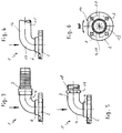
- Figure 1 shows a flange fitting 1, for example for the suction-side connection to a Gear pump not shown can be used.
- the flange fitting 1 includes a flange area 2, a connection area 3 and a transition area 4.
- the recording area 3 and the transition area 4 are specified accordingly Tolerances are nested and preferably connected by brazing.
- the Transition area 4 is in this case designed in the form of a circular arc in cross section, while the receiving area 3 is substantially cylindrical.
- the recording area 3 is in this example provided with a profile 5, on which a hydraulic hose, not shown, is pushed and for example with commercially available hose clamps or press fittings there can be set.
- the flange area 2 is not firmly connected to the transition area 4, but relative to it in the circumferential direction (arrow direction) and in the axial direction movably provided. So that the flange area 2 does not slip off the transition area 4 can, a further sleeve-like component 6 is provided, which follows the postponement of the flange area 2 on the transition area 4, namely on its end area can be attached and connected to the same, for example by brazing.
- the flange area 2 is in order to adapt to the connection diagrams usually provided Pump area provided with several through holes 7, which are usually on a standardized bolt circle diameter are provided.
- the outer peripheral surface 2 'of Flange area 2 is for simplified connection to a pump with a straight line Provide area 14.
- FIG. 2 shows a section through FIG. 1, the following components being recognizable: the flange region 2, the transition region 4 and the receiving region 3 together with the profiled region 5 ′ for the hydraulic hose, which is not shown in any more detail. Also recognizable is the sleeve-like component 6, which is plugged into the area of the end face 8 of the transition area 4 and is preferably connected to it by brazing.
- the transition area 4 and the receiving area 3 are provided with corresponding transition pieces 9, 10 which can be plugged into one another while observing predetermined tolerances and, as already mentioned, can be connected to one another by brazing.
- the sleeve-shaped end part 6 has an outwardly conically widening circumferential surface 11, which is dimensioned in relation to the likewise conically shaped inner circumferential surface 12 of the flange region 2 in such a way that the flange region 2 can be rotated in the circumferential direction on the one hand and on the other hand a defined axial mobility with respect to the transition region 4 having.
- transition area 4 of approximately circular arc shape in cross-section an essentially uniform flow cross-section can be achieved without constrictions over the entire flow area 4 ' , so that an optimal adaptation to the hoses to be used can be brought about.
- the pump used can optionally also be selected to be smaller, at the same time preventing disturbances in this area 4 ' (cavitation, elevated temperature or the like).
- Figures 3 to 5 show the flange fitting 1 according to the invention for different recording options of hoses, pipes or the like
- Figure 3 corresponds essentially to the already mentioned Figures 1 and 2. Recognizable are the flange area 2, the transition area 4 and the profiled receiving area 3 for a hydraulic hose, not shown.
- the sleeve-like component can also be seen 6, which is connected to the transition region 4.
- the flange area 2 falls of the sleeve-like component 6 is avoided in that - as is the case in FIG remove is - opposite conical areas are provided.
- FIG. 4 shows an alternative, the following components being recognizable: the flange region 2 and the sleeve-like component 6.
- a pipe connection is shown in FIG 15 provided, which is curved from a rectilinear region 16 into a extending transition area 17 expires.
- This transition area 17 is as already described in Figure 3 connected to the sleeve-like component 6 by brazing.
- FIG. 5 shows a further alternative, the following components also being recognizable here: the Flange area 2, the sleeve-like component 6, the transition area 4 and the connection area 3.
- the connection area 3 includes a termination element 18, on which one with a Male thread (not shown) provided hose or pipe end attached and with the union nut 19 can be connected.
- FIG. 6 shows a partial representation of the flange region 2.
- the straight line can be seen Area 14 and those arranged on a predetermined bolt circle diameter 20 Through holes 7.
- the relative rotational mobility of the flange area 2 opposite the transition area 4 or 17 about the axis 13 is indicated by the arrow.
Landscapes
- Engineering & Computer Science (AREA)
- General Engineering & Computer Science (AREA)
- Mechanical Engineering (AREA)
- Details And Applications Of Rotary Liquid Pumps (AREA)
- Supports For Pipes And Cables (AREA)
- Joints Allowing Movement (AREA)
Applications Claiming Priority (4)
| Application Number | Priority Date | Filing Date | Title |
|---|---|---|---|
| DE19638053 | 1996-09-18 | ||
| DE19638053 | 1996-09-18 | ||
| DE19653950 | 1996-12-21 | ||
| DE19653950A DE19653950C2 (de) | 1996-09-18 | 1996-12-21 | Flanscharmatur |
Publications (2)
| Publication Number | Publication Date |
|---|---|
| EP0831265A1 true EP0831265A1 (fr) | 1998-03-25 |
| EP0831265B1 EP0831265B1 (fr) | 2001-04-11 |
Family
ID=26029498
Family Applications (1)
| Application Number | Title | Priority Date | Filing Date |
|---|---|---|---|
| EP97116055A Expired - Lifetime EP0831265B1 (fr) | 1996-09-18 | 1997-09-16 | Armature à collerette |
Country Status (2)
| Country | Link |
|---|---|
| EP (1) | EP0831265B1 (fr) |
| AT (1) | ATE200564T1 (fr) |
Cited By (2)
| Publication number | Priority date | Publication date | Assignee | Title |
|---|---|---|---|---|
| EP1712826A1 (fr) * | 2005-04-11 | 2006-10-18 | Dipl.-Ing. K. Dietzel GmbH | Armature à collerette et utilisation d'une telle armature à collerette |
| CN112145772A (zh) * | 2020-09-10 | 2020-12-29 | 湖北天达宇诚科技有限公司 | 一种出液口朝向可任意调节的阀门 |
Citations (11)
| Publication number | Priority date | Publication date | Assignee | Title |
|---|---|---|---|---|
| US2131553A (en) * | 1937-07-21 | 1938-09-27 | Holland Furnace Co | Joint construction |
| US2303311A (en) * | 1941-02-03 | 1942-11-24 | Standard Steel Works | Coupling for thin wall tubing |
| GB759718A (en) * | 1954-09-20 | 1956-10-24 | Cecil Churchill Mackenzie Clou | Improvements in flanges for tubes |
| US2812959A (en) * | 1953-08-21 | 1957-11-12 | Westinghouse Air Brake Co | Flange union fitting with gland expandible into an opening |
| US3224795A (en) * | 1962-09-27 | 1965-12-21 | Conley Corp | Flanged fitting with a reinforcing sleeve |
| FR1555582A (fr) * | 1967-07-11 | 1969-01-31 | ||
| FR2157561A5 (fr) * | 1971-10-20 | 1973-06-01 | Moussiaux Jacques | |
| WO1978000004A1 (fr) * | 1977-06-02 | 1978-12-07 | Advanced Chem Equip Ltd | Tubes et accouplements, et procede d'accouplement de tubes |
| US4503680A (en) * | 1981-11-05 | 1985-03-12 | Allis-Chalmers Corp. | Attachment for exhaust pipe |
| US5511826A (en) * | 1994-06-06 | 1996-04-30 | Certainteed Corporation | Towable nonconductive pipe adapter for a sprinkler having laterally extending surfaces |
| US5518275A (en) * | 1994-08-04 | 1996-05-21 | Tube-Mac Industries Ltd. | Device for coupling and flaring a metal pipe |
-
1997
- 1997-09-16 AT AT97116055T patent/ATE200564T1/de active
- 1997-09-16 EP EP97116055A patent/EP0831265B1/fr not_active Expired - Lifetime
Patent Citations (11)
| Publication number | Priority date | Publication date | Assignee | Title |
|---|---|---|---|---|
| US2131553A (en) * | 1937-07-21 | 1938-09-27 | Holland Furnace Co | Joint construction |
| US2303311A (en) * | 1941-02-03 | 1942-11-24 | Standard Steel Works | Coupling for thin wall tubing |
| US2812959A (en) * | 1953-08-21 | 1957-11-12 | Westinghouse Air Brake Co | Flange union fitting with gland expandible into an opening |
| GB759718A (en) * | 1954-09-20 | 1956-10-24 | Cecil Churchill Mackenzie Clou | Improvements in flanges for tubes |
| US3224795A (en) * | 1962-09-27 | 1965-12-21 | Conley Corp | Flanged fitting with a reinforcing sleeve |
| FR1555582A (fr) * | 1967-07-11 | 1969-01-31 | ||
| FR2157561A5 (fr) * | 1971-10-20 | 1973-06-01 | Moussiaux Jacques | |
| WO1978000004A1 (fr) * | 1977-06-02 | 1978-12-07 | Advanced Chem Equip Ltd | Tubes et accouplements, et procede d'accouplement de tubes |
| US4503680A (en) * | 1981-11-05 | 1985-03-12 | Allis-Chalmers Corp. | Attachment for exhaust pipe |
| US5511826A (en) * | 1994-06-06 | 1996-04-30 | Certainteed Corporation | Towable nonconductive pipe adapter for a sprinkler having laterally extending surfaces |
| US5518275A (en) * | 1994-08-04 | 1996-05-21 | Tube-Mac Industries Ltd. | Device for coupling and flaring a metal pipe |
Cited By (2)
| Publication number | Priority date | Publication date | Assignee | Title |
|---|---|---|---|---|
| EP1712826A1 (fr) * | 2005-04-11 | 2006-10-18 | Dipl.-Ing. K. Dietzel GmbH | Armature à collerette et utilisation d'une telle armature à collerette |
| CN112145772A (zh) * | 2020-09-10 | 2020-12-29 | 湖北天达宇诚科技有限公司 | 一种出液口朝向可任意调节的阀门 |
Also Published As
| Publication number | Publication date |
|---|---|
| ATE200564T1 (de) | 2001-04-15 |
| EP0831265B1 (fr) | 2001-04-11 |
Similar Documents
| Publication | Publication Date | Title |
|---|---|---|
| EP2268957B1 (fr) | Raccord tubulaire | |
| EP0975908B1 (fr) | Collier de serrage pour tuyau | |
| DE2541242A1 (de) | Armatur fuer eine wellrohrleitung | |
| DE19523287A1 (de) | Verbindungsanordnung zum Verbinden eines Abzweigelementes mit einer Hochdruck-Kraftstoffschiene | |
| EP0831265B1 (fr) | Armature à collerette | |
| EP3009680A1 (fr) | Pompe centrifuge à plusieurs étages | |
| DE4035008A1 (de) | Ventilpistole fuer ein hochdruckreinigungsgeraet sowie schlauchkupplung, insbesondere fuer eine solche ventilpistole | |
| DE4336296C1 (de) | Verfahren zur Montage von mit Flanschen zusammenwirkenden Hochdruckschläuchen und -rohren sowie Montagehilfen | |
| EP1484544A1 (fr) | Traversée de conduite pour l'installation d'un tube sanitaire à travers un mur | |
| DE19653950C2 (de) | Flanscharmatur | |
| EP2050994A1 (fr) | Raccord de tuyau | |
| EP1271038B1 (fr) | Raccord vissé pour tubes | |
| DE60306786T2 (de) | Schnellverbindung für einen mit gewinde versehener fluidbauteil | |
| EP1712826A1 (fr) | Armature à collerette et utilisation d'une telle armature à collerette | |
| AT398237B (de) | Rohrschelle | |
| DE3744045A1 (de) | Verbindung | |
| DE3737162C2 (fr) | ||
| EP1992862B1 (fr) | Armature de fermeture, en particulier pour des tuyaux flexibles de haute pression | |
| DE202005020958U1 (de) | Armatur und Verwendung einer Armatur | |
| EP0314823A1 (fr) | Soupape avec couvercle sans vis | |
| CH674068A5 (fr) | ||
| DE202020101198U1 (de) | Ventileinbausatz | |
| DE2324910A1 (de) | Loesbare anschlussverbindung fuer eine z. b. aus metall bestehende starre leitung | |
| DE8527585U1 (de) | Muffe zum lösbaren Zusammenfügen von zwei winklig zueinander angeordneten Rohren | |
| DE10230804A1 (de) | Flanschelement |
Legal Events
| Date | Code | Title | Description |
|---|---|---|---|
| PUAI | Public reference made under article 153(3) epc to a published international application that has entered the european phase |
Free format text: ORIGINAL CODE: 0009012 |
|
| AK | Designated contracting states |
Kind code of ref document: A1 Designated state(s): AT CH DE GB IT LI |
|
| AX | Request for extension of the european patent |
Free format text: AL;LT;LV;RO;SI |
|
| 17P | Request for examination filed |
Effective date: 19980902 |
|
| AKX | Designation fees paid |
Free format text: AT CH DE GB IT LI |
|
| RBV | Designated contracting states (corrected) |
Designated state(s): AT CH DE GB IT LI |
|
| 17Q | First examination report despatched |
Effective date: 19990903 |
|
| GRAG | Despatch of communication of intention to grant |
Free format text: ORIGINAL CODE: EPIDOS AGRA |
|
| GRAG | Despatch of communication of intention to grant |
Free format text: ORIGINAL CODE: EPIDOS AGRA |
|
| GRAH | Despatch of communication of intention to grant a patent |
Free format text: ORIGINAL CODE: EPIDOS IGRA |
|
| GRAH | Despatch of communication of intention to grant a patent |
Free format text: ORIGINAL CODE: EPIDOS IGRA |
|
| GRAA | (expected) grant |
Free format text: ORIGINAL CODE: 0009210 |
|
| AK | Designated contracting states |
Kind code of ref document: B1 Designated state(s): AT CH DE GB IT LI |
|
| REF | Corresponds to: |
Ref document number: 200564 Country of ref document: AT Date of ref document: 20010415 Kind code of ref document: T |
|
| REG | Reference to a national code |
Ref country code: CH Ref legal event code: EP |
|
| REF | Corresponds to: |
Ref document number: 59703344 Country of ref document: DE Date of ref document: 20010517 |
|
| ITF | It: translation for a ep patent filed |
Owner name: DE DOMINICIS & MAYER S.R.L. |
|
| GBT | Gb: translation of ep patent filed (gb section 77(6)(a)/1977) |
Effective date: 20010709 |
|
| REG | Reference to a national code |
Ref country code: CH Ref legal event code: NV Representative=s name: E. BLUM & CO. PATENTANWAELTE |
|
| REG | Reference to a national code |
Ref country code: GB Ref legal event code: IF02 |
|
| PLBE | No opposition filed within time limit |
Free format text: ORIGINAL CODE: 0009261 |
|
| STAA | Information on the status of an ep patent application or granted ep patent |
Free format text: STATUS: NO OPPOSITION FILED WITHIN TIME LIMIT |
|
| 26N | No opposition filed | ||
| REG | Reference to a national code |
Ref country code: CH Ref legal event code: PFA Owner name: INTERHYDRAULIK GESELLSCHAFT FUER HYDRAULIKKOMPONE Free format text: INTERHYDRAULIK GESELLSCHAFT FUER HYDRAULIKKOMPONENTEN MBH#HANS-BOECKLER-STRASSE 20#59348 LUEDINGHAUSEN (DE) -TRANSFER TO- INTERHYDRAULIK GESELLSCHAFT FUER HYDRAULIKKOMPONENTEN MBH#HANS-BOECKLER-STRASSE 20#59348 LUEDINGHAUSEN (DE) |
|
| PGFP | Annual fee paid to national office [announced via postgrant information from national office to epo] |
Ref country code: DE Payment date: 20160921 Year of fee payment: 20 Ref country code: CH Payment date: 20160920 Year of fee payment: 20 Ref country code: GB Payment date: 20160920 Year of fee payment: 20 |
|
| PGFP | Annual fee paid to national office [announced via postgrant information from national office to epo] |
Ref country code: AT Payment date: 20160921 Year of fee payment: 20 |
|
| PGFP | Annual fee paid to national office [announced via postgrant information from national office to epo] |
Ref country code: IT Payment date: 20160922 Year of fee payment: 20 |
|
| REG | Reference to a national code |
Ref country code: DE Ref legal event code: R071 Ref document number: 59703344 Country of ref document: DE |
|
| REG | Reference to a national code |
Ref country code: CH Ref legal event code: PL |
|
| REG | Reference to a national code |
Ref country code: GB Ref legal event code: PE20 Expiry date: 20170915 |
|
| REG | Reference to a national code |
Ref country code: AT Ref legal event code: MK07 Ref document number: 200564 Country of ref document: AT Kind code of ref document: T Effective date: 20170916 |
|
| PG25 | Lapsed in a contracting state [announced via postgrant information from national office to epo] |
Ref country code: GB Free format text: LAPSE BECAUSE OF EXPIRATION OF PROTECTION Effective date: 20170915 |