EP0831265A1 - Flanged armature - Google Patents
Flanged armature Download PDFInfo
- Publication number
- EP0831265A1 EP0831265A1 EP97116055A EP97116055A EP0831265A1 EP 0831265 A1 EP0831265 A1 EP 0831265A1 EP 97116055 A EP97116055 A EP 97116055A EP 97116055 A EP97116055 A EP 97116055A EP 0831265 A1 EP0831265 A1 EP 0831265A1
- Authority
- EP
- European Patent Office
- Prior art keywords
- area
- flange
- fitting according
- flange fitting
- transition
- Prior art date
- Legal status (The legal status is an assumption and is not a legal conclusion. Google has not performed a legal analysis and makes no representation as to the accuracy of the status listed.)
- Granted
Links
Images

Classifications
-
- F—MECHANICAL ENGINEERING; LIGHTING; HEATING; WEAPONS; BLASTING
- F16—ENGINEERING ELEMENTS AND UNITS; GENERAL MEASURES FOR PRODUCING AND MAINTAINING EFFECTIVE FUNCTIONING OF MACHINES OR INSTALLATIONS; THERMAL INSULATION IN GENERAL
- F16L—PIPES; JOINTS OR FITTINGS FOR PIPES; SUPPORTS FOR PIPES, CABLES OR PROTECTIVE TUBING; MEANS FOR THERMAL INSULATION IN GENERAL
- F16L23/00—Flanged joints
- F16L23/02—Flanged joints the flanges being connected by members tensioned axially
- F16L23/024—Flanged joints the flanges being connected by members tensioned axially characterised by how the flanges are joined to, or form an extension of, the pipes
- F16L23/028—Flanged joints the flanges being connected by members tensioned axially characterised by how the flanges are joined to, or form an extension of, the pipes the flanges being held against a shoulder
- F16L23/0283—Flanged joints the flanges being connected by members tensioned axially characterised by how the flanges are joined to, or form an extension of, the pipes the flanges being held against a shoulder the collar being integral with the pipe
Definitions
- the invention relates to a flange fitting, in particular for the suction-side connection Pump.
- General St.d.T. is to hydraulic pumps, especially gear pumps, with larger Delivery volume on the suction side with a generally standardized connection diagram (Bolt circle diameter). Those for connecting hose lines in particular Commercially available flange connections are used, but not always optimal solution.
- connection elements used so far allow the use of cables with a large cross-section, but with A closer look at the flanges reveals that immediately before the pump suction mouth design-related cross-sectional constrictions of sometimes 50% and more are not uncommon are.
- the advantage of a well-dimensioned line is thus again in the connection area canceled, which ultimately leads to the need for greater pump performance.
- This narrowing of the cross-section in the connection area occurs due to the nozzle effect undesirable temperature increases and turbulence in the hydraulic medium which can ultimately lead to premature failure of the flange fitting (e.g. due to cavitation or too high temperature).
- the flange fitting with four screws on the bolt circle diameter are predictably connected to the respective hydraulic pump.
- This four-hole attachment leaves only four defined connection directions (90 °, 180 °, 270 °, 360 ° to the pump axis) of the incoming Line too, which, depending on the arrangement of the pump, causes problems with the attachment the flange fitting can adjust.
- With usually also necessary additional Screw connections, etc. in the area of the hose or pipe fastening the access for these connections with spanner sizes from SW 36 to SW 55 even more difficult. Often leakages are the result, since the screw connections are not properly tightened can destroy.
- the object of the invention is to overcome the disadvantages of the St.d.T. to overcome and a To design flange fittings that are easy to handle and even in confined spaces can be used variably without increasing assembly and additional costs connected is.
- a flange fitting especially for the suction connection to a pump, in particular a gear pump or the like, with a to a component, in particular a pump, connectable flange area, a transition area and a receiving area for a hose or a pipe, -with the flange area relative to the transition area or the receiving area in operative connection with the transition area is movable relative to the flange area.
- hose ends can be profiled Recording area either just plugged in or fixed there using hose clamps be, or there may be pipe ends at the transition area or immediately be soldered to the flange area, for example.
- Threaded pieces either directly at the transition area or at the flange area to be provided in order to attach hose or pipe ends by means of union nuts or the like.
- the subject of the invention can be used in many ways and allows compared to the St.d.T. a easy mounting on corresponding components, especially on pumps such as gear pumps or the like., Because a relative mobility of the individual components of the flange fitting against each other and against the corresponding components.
- the advantages of the subject matter of the invention over the previous St.d.T. are essentially is based on the fact that an optimal flow of the hydraulic medium while avoiding of throttling points is possible with the same connection.
- the outlet direction of the hose or Pipe area is freely adjustable, in both directions between 0 and 360 °, with an axial relative mobility at least opposite the flange area the transition area is given.
- the assembly effort is as already explained as small to look at, for example the hose or pipe connection directly can be integrated.
- the recording area is either different Individual parts formed, which can be plugged into one another and preferably by Brazing can be connected to each other, or the connection areas are directly on Flange area or provided at the transition area.
- the overall height can also be compared the St.d.T. can be reduced since no more complicated forgings are used. This measure also results in a reduced cost.
- Figure 1 shows a flange fitting 1, for example for the suction-side connection to a Gear pump not shown can be used.
- the flange fitting 1 includes a flange area 2, a connection area 3 and a transition area 4.
- the recording area 3 and the transition area 4 are specified accordingly Tolerances are nested and preferably connected by brazing.
- the Transition area 4 is in this case designed in the form of a circular arc in cross section, while the receiving area 3 is substantially cylindrical.
- the recording area 3 is in this example provided with a profile 5, on which a hydraulic hose, not shown, is pushed and for example with commercially available hose clamps or press fittings there can be set.
- the flange area 2 is not firmly connected to the transition area 4, but relative to it in the circumferential direction (arrow direction) and in the axial direction movably provided. So that the flange area 2 does not slip off the transition area 4 can, a further sleeve-like component 6 is provided, which follows the postponement of the flange area 2 on the transition area 4, namely on its end area can be attached and connected to the same, for example by brazing.
- the flange area 2 is in order to adapt to the connection diagrams usually provided Pump area provided with several through holes 7, which are usually on a standardized bolt circle diameter are provided.
- the outer peripheral surface 2 'of Flange area 2 is for simplified connection to a pump with a straight line Provide area 14.
- FIG. 2 shows a section through FIG. 1, the following components being recognizable: the flange region 2, the transition region 4 and the receiving region 3 together with the profiled region 5 ′ for the hydraulic hose, which is not shown in any more detail. Also recognizable is the sleeve-like component 6, which is plugged into the area of the end face 8 of the transition area 4 and is preferably connected to it by brazing.
- the transition area 4 and the receiving area 3 are provided with corresponding transition pieces 9, 10 which can be plugged into one another while observing predetermined tolerances and, as already mentioned, can be connected to one another by brazing.
- the sleeve-shaped end part 6 has an outwardly conically widening circumferential surface 11, which is dimensioned in relation to the likewise conically shaped inner circumferential surface 12 of the flange region 2 in such a way that the flange region 2 can be rotated in the circumferential direction on the one hand and on the other hand a defined axial mobility with respect to the transition region 4 having.
- transition area 4 of approximately circular arc shape in cross-section an essentially uniform flow cross-section can be achieved without constrictions over the entire flow area 4 ' , so that an optimal adaptation to the hoses to be used can be brought about.
- the pump used can optionally also be selected to be smaller, at the same time preventing disturbances in this area 4 ' (cavitation, elevated temperature or the like).
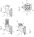
- Figures 3 to 5 show the flange fitting 1 according to the invention for different recording options of hoses, pipes or the like
- Figure 3 corresponds essentially to the already mentioned Figures 1 and 2. Recognizable are the flange area 2, the transition area 4 and the profiled receiving area 3 for a hydraulic hose, not shown.
- the sleeve-like component can also be seen 6, which is connected to the transition region 4.
- the flange area 2 falls of the sleeve-like component 6 is avoided in that - as is the case in FIG remove is - opposite conical areas are provided.
- FIG. 4 shows an alternative, the following components being recognizable: the flange region 2 and the sleeve-like component 6.
- a pipe connection is shown in FIG 15 provided, which is curved from a rectilinear region 16 into a extending transition area 17 expires.
- This transition area 17 is as already described in Figure 3 connected to the sleeve-like component 6 by brazing.
- FIG. 5 shows a further alternative, the following components also being recognizable here: the Flange area 2, the sleeve-like component 6, the transition area 4 and the connection area 3.
- the connection area 3 includes a termination element 18, on which one with a Male thread (not shown) provided hose or pipe end attached and with the union nut 19 can be connected.
- FIG. 6 shows a partial representation of the flange region 2.
- the straight line can be seen Area 14 and those arranged on a predetermined bolt circle diameter 20 Through holes 7.
- the relative rotational mobility of the flange area 2 opposite the transition area 4 or 17 about the axis 13 is indicated by the arrow.
Abstract
Description
Die Erfindung betrifft eine Flanscharmatur, insbesondere für den saugseitigen Anschluß an Pumpen.The invention relates to a flange fitting, in particular for the suction-side connection Pump.
Allgemeiner St.d.T. ist es, Hydraulikpumpen, insbesondere Zahnradpumpen, mit größerem Fördervolumen saugseitig mit einem in der Regel genormten Anschlußbild (Lochkreisdurchmesser) vorzusehen. Die zum Anschluß von insbesondere Schlauchleitungen eingesetzten handelsüblichen Flanschanschlüsse sind eine praktizierte, jedoch nicht immer optimale Lösung.General St.d.T. is to hydraulic pumps, especially gear pumps, with larger Delivery volume on the suction side with a generally standardized connection diagram (Bolt circle diameter). Those for connecting hose lines in particular Commercially available flange connections are used, but not always optimal solution.
Pumpen mit großem Fördervolumen verlangen in der Regel eine optimale Ölversorgung bei geringstmöglichem Unterdruck auf der Saugseite. Nur durch diese Art der Versorgung kann eine lange Lebensdauer sichergestellt werden. Die bisher zum Einsatz gelangten Anschlußelemente erlauben zwar den Einsatz von Leitungen mit großem Querschnitt, wobei jedoch bei genauer Betrachtung der Flansche festzustellen ist, daß unmittelbar vor dem Pumpensaugmund bauartbedingte Querschnittsverengungen von teilweise 50 % und mehr nicht ungewöhnlich sind. Der Vorteil einer gut dimensionierten Leitung wird somit im Anschlußbereich wieder aufgehoben, was letztendlich zur Notwendigkeit einer größeren Pumpenleistung führt. Infolge dieser Querschnittsverengung im Anschlußbereich treten durch den sich einstellenden Düseneffekt unerwünschte Temperaturerhöhungen und Verwirbelungen des Hydraulikmediums auf, was letztendlich auch zu einem frühzeitigen Ausfall der Flanscharmatur führen kann (z.B. durch Kavitation oder zu hohe Temperatur).Pumps with a large delivery volume generally require an optimal oil supply lowest possible vacuum on the suction side. Only through this type of care can a long service life can be ensured. The connection elements used so far allow the use of cables with a large cross-section, but with A closer look at the flanges reveals that immediately before the pump suction mouth design-related cross-sectional constrictions of sometimes 50% and more are not uncommon are. The advantage of a well-dimensioned line is thus again in the connection area canceled, which ultimately leads to the need for greater pump performance. As a result This narrowing of the cross-section in the connection area occurs due to the nozzle effect undesirable temperature increases and turbulence in the hydraulic medium which can ultimately lead to premature failure of the flange fitting (e.g. due to cavitation or too high temperature).
Üblicherweise wird die Flanscharmatur mit vier Schrauben, die auf dem Lochkreisdurchmesser vorsehbar sind mit der jeweiligen Hydraulikpumpe verbunden. Diese Vierlochbefestigung läßt nur vier definierte Anschlußrichtungen (90°, 180°, 270°, 360° zur Pumpenachse) der ankommenden Leitung zu, wodurch sich je nach Anordnung der Pumpe Probleme bei der Befestigung der Flanscharmatur einstellen können. Mit in der Regel ebenfalls notwendigen zusätzlichen Verschraubungen, u.a. im Bereich der Schlauch- bzw. Rohrleitungsbefestigung, wird der Zugang zu diesen Anschlüssen mit Schlüsselweiten von SW 36 bis SW 55 noch erschwert. Häufig sind hierbei Leckagen die Folge, da die Verschraubungen nicht ordnungsgemäß angezogen verden können.Usually, the flange fitting with four screws on the bolt circle diameter are predictably connected to the respective hydraulic pump. This four-hole attachment leaves only four defined connection directions (90 °, 180 °, 270 °, 360 ° to the pump axis) of the incoming Line too, which, depending on the arrangement of the pump, causes problems with the attachment the flange fitting can adjust. With usually also necessary additional Screw connections, etc. in the area of the hose or pipe fastening, the access for these connections with spanner sizes from SW 36 to SW 55 even more difficult. Often leakages are the result, since the screw connections are not properly tightened can destroy.
Ziel des Erfindungsgegenstandes ist es, die Nachteile des St.d.T. zu überwinden und eine Flanscharmatur zu konzipieren, die einfach handhabbar und auch bei beengten Raumverhältnissen variabel einsetzbar ist, ohne daß ein erhöhter Montage- und Mehrkostenaufwand damit verbunden ist. The object of the invention is to overcome the disadvantages of the St.d.T. to overcome and a To design flange fittings that are easy to handle and even in confined spaces can be used variably without increasing assembly and additional costs connected is.
Dieses Ziel wird erreicht durch eine Flanscharmatur, insbesondere für den saugseitigen Anschluß an eine Pumpe, insbesondere eine Zahnradpumpe oder dgl., mit einem an ein Bauteil, insbesondere eine Pumpe, anschließbaren Flanschbereich, einen Übergangsbereich sowie einen Aufnahmebereich für einen Schlauch oder ein Rohr, -bei der Flanschbereich relativ zum Übergangsbereich bzw. der in Wirkverbindung mit dem Übergangsbereich stehende Aufnahmebereich relativ zum Flanschbereich beweglich ist.This goal is achieved with a flange fitting, especially for the suction connection to a pump, in particular a gear pump or the like, with a to a component, in particular a pump, connectable flange area, a transition area and a receiving area for a hose or a pipe, -with the flange area relative to the transition area or the receiving area in operative connection with the transition area is movable relative to the flange area.
Vorteilhafte Weiterbildungen des Erfindungsgegenstandes sind den Unteransprüchen zu entnehmen.Advantageous further developments of the subject matter of the invention can be found in the subclaims.
Mit dem Erfindungsgegenstand ist es möglich, eine relative Beweglichkeit der einzelnen Komponenten der Flanscharmatur gegenüber damit zu verbindenden Bauteilen, insbesondere Pumpen, zu erzeugen, die eine wesentlich einfachere Handhabung als beim bisher bekannten St.d.T. ermöglicht. Die Flanscharmatur ist sowohl für Schläuche als auch für Rohre verwendbar, wobei unterschiedlichste Anschlußmöglichkeiten insbesondere im Bereich des Aufnahmebereiches realisiert werden können. So können beispielsweise Schlauchenden auf einen profilierten Aufnahmebereich entweder nur aufgesteckt oder mittels Schlauchklemmen dort festgelegt werden, oder aber es können Rohrleitungsenden am Übergangsbereich oder unmittelbar am Flanschbereich beispielsweise festgelötet werden. Desweiteren besteht auch die Möglichkeit, Gewindestücke entweder unmittelbar am Übergangsbereich oder aber am Flanschbereich vorzusehen, um hier Schlauch- oder Rohrenden mittels Überwurfmuttern oder dgl. zu befestigen.With the subject matter of the invention it is possible to have a relative mobility of the individual components the flange fitting in relation to components to be connected, in particular Pumps, which are much easier to use than the previously known St.d.T. enables. The flange fitting can be used for both hoses and pipes, different connection options, especially in the area of the recording area can be realized. For example, hose ends can be profiled Recording area either just plugged in or fixed there using hose clamps be, or there may be pipe ends at the transition area or immediately be soldered to the flange area, for example. Furthermore, there is also the possibility Threaded pieces either directly at the transition area or at the flange area to be provided in order to attach hose or pipe ends by means of union nuts or the like.
Der Erfindungsgegenstand ist vielseitig einsetzbar und erlaubt gegenüber dem St.d.T. eine einfache Montage an korrespondierenden Bauteilen, insbesondere an Pumpen, wie Zahnradpumpen oder dgl., da eine relative Beweglichkeit der Einzelkomponenten der Flanscharmatur gegeneinander und gegenüber den korrespondierenden Bauteilen gegeben ist.The subject of the invention can be used in many ways and allows compared to the St.d.T. a easy mounting on corresponding components, especially on pumps such as gear pumps or the like., Because a relative mobility of the individual components of the flange fitting against each other and against the corresponding components.
Infolge der relativen, insbesondere Drehbeweglichkeit des Flanschbereiches gegenüber dem verbleibenden Schlauch- bzw. Rohrleitungsbereich oder umgekehrt, kann nunmehr eine variable Anpassung an örtliche Gegebenheiten hergestellt werden, wodurch sich letztendlich ein vereinfachter Montageaufwand der Flanscharmatur selber sowie des ggf. damit in Wirkverbindung zu bringenden Schlauches/Rohres auch unter beengten Einbaubedingungen einstellt.As a result of the relative, in particular rotational mobility of the flange area relative to the remaining hose or pipe area or vice versa, can now be a variable Adaptation to local conditions are established, which ultimately leads to a Simplified assembly effort of the flange fitting itself and, if necessary, in operative connection with it adjusts the hose / pipe to be brought even under restricted installation conditions.
Die Vorteile des Erfindungsgegenstandes gegenüber dem bisherigen St.d.T. sind im wesentlichen darin begründet, daß ein optimaler Durchfluß des Hydraulikmediums unter Vermeidung von Drosselstellen bei gleichem Anschluß möglich ist. Die Abgangsrichtung des Schlauch- bzw. Rohrleitungsbereiches ist frei einstellbar und zwar in beiden Drehrichtungen zwischen 0 und 360°, wobei auch eine axiale Relativbeweglichkeit zumindest des Flanschbereiches gegenüber dem Übergangsbereich gegeben ist. Der Montageaufwand ist wie bereits dargelegt als gering anzusehen, wobei beispielsweise auch der Schlauch- bzw. der Rohranschluß unmittelbar integriert werden kann. Zu diesem Zweck ist der Aufnahmebereich entweder aus verschiedenen Einzelteilen gebildet, die beispielsweise ineinandersteckbar und vorzugsweise durch Hartlöten miteinander verbindbar sind, oder aber die Anschlußbereiche sind unmittelbar am Flanschbereich bzw. am Übergangsbereich vorgesehen. Auch die Bauhöhe kann gegenüber dem St.d.T. reduziert werden, da keine komplizierten Schmiedeteile mehr zum Einsatz gelangen. Durch diese Maßnahme stellt sich ebenfalls eine reduzierten Kostenaufwand ein.The advantages of the subject matter of the invention over the previous St.d.T. are essentially is based on the fact that an optimal flow of the hydraulic medium while avoiding of throttling points is possible with the same connection. The outlet direction of the hose or Pipe area is freely adjustable, in both directions between 0 and 360 °, with an axial relative mobility at least opposite the flange area the transition area is given. The assembly effort is as already explained as small to look at, for example the hose or pipe connection directly can be integrated. For this purpose, the recording area is either different Individual parts formed, which can be plugged into one another and preferably by Brazing can be connected to each other, or the connection areas are directly on Flange area or provided at the transition area. The overall height can also be compared the St.d.T. can be reduced since no more complicated forgings are used. This measure also results in a reduced cost.
Der Erfindungsgegenstand ist anhand eines Ausführungsbeispieles in der Zeichnung dargestellt und wird wie folgt beschrieben. Es zeigen:
Figur 1- - perspektivische Darstellung der erfindungsgemäßen Flanscharmatur
Figur 2- - Schnitt durch
Figur 1 Figuren 3 bis 5- - Prinzipskizzen unterschiedlicher Anschlußmöglichkeiten
Figur 6- - Teildarstellung des relativ beweglichen Flanschbereiches.
- Figure 1
- - Perspective view of the flange fitting according to the invention
- Figure 2
- - Section through Figure 1
- Figures 3 to 5
- - Basic sketches of different connection options
- Figure 6
- - Partial representation of the relatively movable flange area.
Figur 1 zeigt eine Flanscharmatur 1, die beispielsweise für den saugseitigen Anschluß an eine
nicht weiter dargestellte Zahnradpumpe zum Einsatz gelangen kann. Die Flanscharmatur 1
beinhaltet einen Flanschbereich 2, einen Anschlußbereich 3 sowie einen Übergangsbereich 4.
Der Aufnahmebereich 3 sowie der Übergangsbereich 4 werden unter Vorgabe entsprechender
Toleranzen ineinandergesteckt und vorzugsweise durch Hartlöten miteinander verbunden. Der
Übergangsbereich 4 ist hierbei im Querschnitt kreisbogenförmig ausgebildet, während der Aufnahmebereich
3 im wesentlichen zylindrisch ist. Der Aufnahmebereich 3 ist in diesem Beispiel
mit einem Profil 5 versehen, auf welches ein nicht weiter dargestellter Hydraulikschlauch aufgeschoben
und beispielsweise mit handelsüblichen Schlauchschellen oder Pressfassungen dort
festgelegt werden kann. Der Flanschbereich 2 ist mit dem Übergangsbereich 4 nicht fest verbunden,
sondern relativ zu diesem in Umfangsrichtung (Pfeilrichtung) sowie in axialer Richtung
beweglich vorgesehen. Damit der Flanschbereich 2 nicht vom Übergangsbereich 4 abrutschen
kann, ist ein weiteres hülsenartiges Bauteil 6 vorgesehen, welches im Anschluß an das Aufschieben
des Flanschbereiches 2 auf den Übergangsbereich 4 und zwar auf dessen Endbereich
aufgesteckt und beispielsweise durch Hartlöten mit demselben verbunden werden kann.
Der Flanschbereich 2 ist zur Anpassung an üblicherweise vorgesehene Anschlußbilder im
Pumpenbereich mit mehreren Durchgangsbohrungen 7 versehen, die auf einem in der Regel
genormten Lochkreisdurchmesser vorgesehen sind. Die äußere Umfangsfläche 2' des
Flanschbereiches 2 ist zum vereinfachten Anschluß an eine Pumpe mit einem geradlinig verlaufenden
Bereich 14 versehen. Figure 1 shows a
Figur 2 zeigt einen Schnitt durch Figur 1, wobei folgende Bauteile erkennbar sind: der Flanschbereich
2, der Übergangsbereich 4 sowie der Aufnahmebereich 3 samt profiliertem Bereich 5'
für den nicht weiter dargestellten Hydraulikschlauch. Ferner erkennbar ist das hülsenartige
Bauteil 6, welches im Bereich der Stirnfläche 8 des Übergangsbereiches 4 aufgesteckt und
vorzugsweise durch Hartlöten mit demselben verbunden ist. Der Übergangsbereich 4 sowie der
Aufnahmebereich 3 sind mit entsprechenden Übergangsstücken 9,10 versehen, die unter Einhaltung
vorgegebener Toleranzen ineinandersteckbar und wie bereits angesprochen durch
Hartlöten miteinander verbindbar sind. Das hülsenförmige Abschlußteil 6 weist eine nach außen
sich konisch erweiternde Umfangsfläche 11 auf, die gegenüber der ebenfalls konisch gestalteten
inneren Umfangsfläche 12 des Flanschbereiches 2 so dimensioniert ist, daß der
Flanschbereich 2 einerseits in Umfangsrichtung drehbeweglich ist und andererseits eine definierte
axiale Beweglichkeit gegenüber dem Übergangsbereich 4 aufweist. Gleiches gilt natürlich
auch für den Aufnahmebereich 3, der im Anschluß an die Positionierung des Flanschbereiches
2 um 360° in beiden Umfangsrichtungen um die Achse 13 geschwenkt werden kann, so
daß ein problemloses Aufstecken des nicht weiter dargestellten Schlauches auch in beengten
Einbauzonen herbeigeführt werden kann. Unter Verwendung eines im Querschnitt etwa kreisbogenförmig
ausgebildeten Übergangsbereiches 4 kann über den gesamten Durchflußbereich
4'hinweg ein im wesentlichen gleichmäßiger Durchflußquerschnitt ohne Engstellen realisiert
werden, so daß eine optimale Anpassung an die zu verwendenden Schläuche herbeigeführt
werden kann. Infolge dieses optimierten Querschnittsprofils im Durchflußbereich 4' kann ggf.
auch die zum Einsatz gelangende Pumpe kleiner gewählt werden, wobei gleichzeitig Störungen
in diesem Bereich 4' (Kavitation, erhöhte Temperatur oder dgl.) vermieden werden.FIG. 2 shows a section through FIG. 1, the following components being recognizable: the
Infolge der relativen Drehbeweglichkeit des Flanschbereiches 2 gegenüber dem Übergangsbereich
4 bzw. umgekehrt, können eine Vielzahl von Anschluß- und Bewegungsmöglichkeiten
innerhalb beengter Bauräume realisiert werden, die zu einer nicht unerheblichen Montagevereinfachung
gegenüber den damit zu verbindenden Bauteilen (Pumpen, Schläuche, Rohre
oder dgl.) führen.As a result of the relative rotational mobility of the
Die Figuren 3 bis 5 zeigen die erfindungsgemäße Flanscharmatur 1 für unterschiedliche Aufnahmemöglichkeiten von Schläuchen, Rohren oder dgl.Figures 3 to 5 show the flange fitting 1 according to the invention for different recording options of hoses, pipes or the like
Figur 3 entspricht im wesentlichen den bereits angesprochenen Figuren 1 und 2. Erkennbar
sind der Flanschbereich 2, der Übergangsbereich 4 sowie der profilierte Aufnahmebereich 3 für
einen nicht weiter dargestellten Hydraulikschlauch. Ferner erkennbar ist das hülsenartige Bauteil
6, das mit dem Übergangsbereich 4 verbunden ist. Ein Herabfallen des Flanschbereiches 2
vom hülsenartigen Bauteil 6 wird dadurch vermieden, daß - wie dies insbesondere Figur 2 zu
entnehmen ist - entgegengesetzt konisch ausgebildete Bereiche vorgesehen sind. Figure 3 corresponds essentially to the already mentioned Figures 1 and 2. Recognizable
are the
Figur 4 zeigt eine Alternative, wobei folgende Bauteile erkennbar sind: der Flanschbereich 2
sowie das hülsenartig ausgebildete Bauteil 6. Abweichend zu Figur 3 ist in Figur 4 ein Rohrleitungsanschluß
15 vorgesehen, der aus einem geradlinig verlaufenden Bereich 16 in einen gekrümmt
verlaufenden Übergangsbereich 17 ausläuft. Dieser Übergangsbereich 17 ist wie bereits
in Figur 3 beschrieben mit dem hülsenartigen Bauteil 6 durch Hartlöten verbunden.FIG. 4 shows an alternative, the following components being recognizable: the
Figur 5 zeigt eine weitere Alternative, wobei auch hier folgende Bauteile erkennbar sind: der
Flanschbereich 2, das hülsenartige Bauteil 6, der Übergangsbereich 4 sowie der Anschlußbereich
3. Der Anschlußbereich 3 beinhaltet ein Abschlußelement 18, auf welches ein mit einem
Außengewinde (nicht dargestellt) versehenes Schlauch- oder Rohrende aufgesteckt und mit
der Überwurfmutter 19 verbunden werden kann.FIG. 5 shows a further alternative, the following components also being recognizable here: the
Figur 6 zeigt eine Teildarstellung des Flanschbereiches 2. Erkennbar ist der geradlinig verlaufende
Bereich 14 sowie die auf einem vorgegebenen Lochkreisdurchmesser 20 angeordneten
Durchgangsbohrungen 7. Die relative Drehbeweglichkeit des Flanschbereiches 2 gegenüber
dem Übergangsbereich 4 bzw. 17 um die Achse 13 ist durch den Pfeil angedeutet.FIG. 6 shows a partial representation of the
Claims (17)
Applications Claiming Priority (4)
| Application Number | Priority Date | Filing Date | Title |
|---|---|---|---|
| DE19638053 | 1996-09-18 | ||
| DE19638053 | 1996-09-18 | ||
| DE19653950 | 1996-12-21 | ||
| DE19653950A DE19653950C2 (en) | 1996-09-18 | 1996-12-21 | Flange fitting |
Publications (2)
| Publication Number | Publication Date |
|---|---|
| EP0831265A1 true EP0831265A1 (en) | 1998-03-25 |
| EP0831265B1 EP0831265B1 (en) | 2001-04-11 |
Family
ID=26029498
Family Applications (1)
| Application Number | Title | Priority Date | Filing Date |
|---|---|---|---|
| EP97116055A Expired - Lifetime EP0831265B1 (en) | 1996-09-18 | 1997-09-16 | Flanged armature |
Country Status (2)
| Country | Link |
|---|---|
| EP (1) | EP0831265B1 (en) |
| AT (1) | ATE200564T1 (en) |
Cited By (2)
| Publication number | Priority date | Publication date | Assignee | Title |
|---|---|---|---|---|
| EP1712826A1 (en) * | 2005-04-11 | 2006-10-18 | Dipl.-Ing. K. Dietzel GmbH | Flanged fitting and use of such a flanged fitting |
| CN112145772A (en) * | 2020-09-10 | 2020-12-29 | 湖北天达宇诚科技有限公司 | Valve with liquid outlet facing direction capable of being adjusted randomly |
Citations (11)
| Publication number | Priority date | Publication date | Assignee | Title |
|---|---|---|---|---|
| US2131553A (en) * | 1937-07-21 | 1938-09-27 | Holland Furnace Co | Joint construction |
| US2303311A (en) * | 1941-02-03 | 1942-11-24 | Standard Steel Works | Coupling for thin wall tubing |
| GB759718A (en) * | 1954-09-20 | 1956-10-24 | Cecil Churchill Mackenzie Clou | Improvements in flanges for tubes |
| US2812959A (en) * | 1953-08-21 | 1957-11-12 | Westinghouse Air Brake Co | Flange union fitting with gland expandible into an opening |
| US3224795A (en) * | 1962-09-27 | 1965-12-21 | Conley Corp | Flanged fitting with a reinforcing sleeve |
| FR1555582A (en) * | 1967-07-11 | 1969-01-31 | ||
| FR2157561A5 (en) * | 1971-10-20 | 1973-06-01 | Moussiaux Jacques | |
| WO1978000004A1 (en) * | 1977-06-02 | 1978-12-07 | Advanced Chem Equip Ltd | Pipes and couplings and method of coupling pipes |
| US4503680A (en) * | 1981-11-05 | 1985-03-12 | Allis-Chalmers Corp. | Attachment for exhaust pipe |
| US5511826A (en) * | 1994-06-06 | 1996-04-30 | Certainteed Corporation | Towable nonconductive pipe adapter for a sprinkler having laterally extending surfaces |
| US5518275A (en) * | 1994-08-04 | 1996-05-21 | Tube-Mac Industries Ltd. | Device for coupling and flaring a metal pipe |
-
1997
- 1997-09-16 EP EP97116055A patent/EP0831265B1/en not_active Expired - Lifetime
- 1997-09-16 AT AT97116055T patent/ATE200564T1/en active
Patent Citations (11)
| Publication number | Priority date | Publication date | Assignee | Title |
|---|---|---|---|---|
| US2131553A (en) * | 1937-07-21 | 1938-09-27 | Holland Furnace Co | Joint construction |
| US2303311A (en) * | 1941-02-03 | 1942-11-24 | Standard Steel Works | Coupling for thin wall tubing |
| US2812959A (en) * | 1953-08-21 | 1957-11-12 | Westinghouse Air Brake Co | Flange union fitting with gland expandible into an opening |
| GB759718A (en) * | 1954-09-20 | 1956-10-24 | Cecil Churchill Mackenzie Clou | Improvements in flanges for tubes |
| US3224795A (en) * | 1962-09-27 | 1965-12-21 | Conley Corp | Flanged fitting with a reinforcing sleeve |
| FR1555582A (en) * | 1967-07-11 | 1969-01-31 | ||
| FR2157561A5 (en) * | 1971-10-20 | 1973-06-01 | Moussiaux Jacques | |
| WO1978000004A1 (en) * | 1977-06-02 | 1978-12-07 | Advanced Chem Equip Ltd | Pipes and couplings and method of coupling pipes |
| US4503680A (en) * | 1981-11-05 | 1985-03-12 | Allis-Chalmers Corp. | Attachment for exhaust pipe |
| US5511826A (en) * | 1994-06-06 | 1996-04-30 | Certainteed Corporation | Towable nonconductive pipe adapter for a sprinkler having laterally extending surfaces |
| US5518275A (en) * | 1994-08-04 | 1996-05-21 | Tube-Mac Industries Ltd. | Device for coupling and flaring a metal pipe |
Cited By (2)
| Publication number | Priority date | Publication date | Assignee | Title |
|---|---|---|---|---|
| EP1712826A1 (en) * | 2005-04-11 | 2006-10-18 | Dipl.-Ing. K. Dietzel GmbH | Flanged fitting and use of such a flanged fitting |
| CN112145772A (en) * | 2020-09-10 | 2020-12-29 | 湖北天达宇诚科技有限公司 | Valve with liquid outlet facing direction capable of being adjusted randomly |
Also Published As
| Publication number | Publication date |
|---|---|
| ATE200564T1 (en) | 2001-04-15 |
| EP0831265B1 (en) | 2001-04-11 |
Similar Documents
| Publication | Publication Date | Title |
|---|---|---|
| EP2268957B1 (en) | Pipe coupling | |
| EP0975908B1 (en) | Pipe clamp | |
| DE2541242A1 (en) | FITTING FOR A CORRUGATED PIPE | |
| DE19523287A1 (en) | Connection arrangement for connecting a branch element to a high-pressure fuel rail | |
| DE102006009602A1 (en) | Carrying arrangement for container, e.g. fuel tank, on carrying component of truck has bracket as one-piece component that can be directly mounted on carrying component or adapter element via reversible connection arrangement | |
| EP0831265B1 (en) | Flanged armature | |
| DE4035008A1 (en) | VALVE GUN FOR A HIGH PRESSURE CLEANER AND HOSE COUPLING, ESPECIALLY FOR SUCH A VALVE GUN | |
| DE4336296C1 (en) | Process for mounting high-pressure hoses and tubes interacting with flanges, and mounting aids | |
| EP1484544A1 (en) | Conduit feed-through for the installation of a sanitary tube through a wall | |
| DE19653950C2 (en) | Flange fitting | |
| EP2050994A1 (en) | Pipe connection | |
| EP1271038B1 (en) | Threaded tube connector | |
| DE60306786T2 (en) | QUICK CONNECTION FOR A THREADED FLUID COMPONENT | |
| EP1712826A1 (en) | Flanged fitting and use of such a flanged fitting | |
| AT398237B (en) | PIPE CLAMP | |
| DE3744045A1 (en) | Connection | |
| DE3737162C2 (en) | ||
| EP1992862B1 (en) | Connecting fitting, in particular for high pressure hoses | |
| DE202005020958U1 (en) | Pipe section for being connected to pump, comprises flange with curved slots for being joined to other component | |
| EP0314823A1 (en) | Valve with screwless cap | |
| CH674068A5 (en) | ||
| DE202020101198U1 (en) | Valve installation kit | |
| DE2324910A1 (en) | DETACHABLE CONNECTION FOR A RIGID LINE, FOR EXAMPLE, MADE OF METAL | |
| DE8527585U1 (en) | Socket for the detachable joining of two pipes arranged at an angle to one another | |
| DE10230804A1 (en) | Flange connector for joining two pipes or pipe and tap has integral sleeve attached to flange whose inner diameter is at least as great as outer diameter of pipe |
Legal Events
| Date | Code | Title | Description |
|---|---|---|---|
| PUAI | Public reference made under article 153(3) epc to a published international application that has entered the european phase |
Free format text: ORIGINAL CODE: 0009012 |
|
| AK | Designated contracting states |
Kind code of ref document: A1 Designated state(s): AT CH DE GB IT LI |
|
| AX | Request for extension of the european patent |
Free format text: AL;LT;LV;RO;SI |
|
| 17P | Request for examination filed |
Effective date: 19980902 |
|
| AKX | Designation fees paid |
Free format text: AT CH DE GB IT LI |
|
| RBV | Designated contracting states (corrected) |
Designated state(s): AT CH DE GB IT LI |
|
| 17Q | First examination report despatched |
Effective date: 19990903 |
|
| GRAG | Despatch of communication of intention to grant |
Free format text: ORIGINAL CODE: EPIDOS AGRA |
|
| GRAG | Despatch of communication of intention to grant |
Free format text: ORIGINAL CODE: EPIDOS AGRA |
|
| GRAH | Despatch of communication of intention to grant a patent |
Free format text: ORIGINAL CODE: EPIDOS IGRA |
|
| GRAH | Despatch of communication of intention to grant a patent |
Free format text: ORIGINAL CODE: EPIDOS IGRA |
|
| GRAA | (expected) grant |
Free format text: ORIGINAL CODE: 0009210 |
|
| AK | Designated contracting states |
Kind code of ref document: B1 Designated state(s): AT CH DE GB IT LI |
|
| REF | Corresponds to: |
Ref document number: 200564 Country of ref document: AT Date of ref document: 20010415 Kind code of ref document: T |
|
| REG | Reference to a national code |
Ref country code: CH Ref legal event code: EP |
|
| REF | Corresponds to: |
Ref document number: 59703344 Country of ref document: DE Date of ref document: 20010517 |
|
| ITF | It: translation for a ep patent filed |
Owner name: DE DOMINICIS & MAYER S.R.L. |
|
| GBT | Gb: translation of ep patent filed (gb section 77(6)(a)/1977) |
Effective date: 20010709 |
|
| REG | Reference to a national code |
Ref country code: CH Ref legal event code: NV Representative=s name: E. BLUM & CO. PATENTANWAELTE |
|
| REG | Reference to a national code |
Ref country code: GB Ref legal event code: IF02 |
|
| PLBE | No opposition filed within time limit |
Free format text: ORIGINAL CODE: 0009261 |
|
| STAA | Information on the status of an ep patent application or granted ep patent |
Free format text: STATUS: NO OPPOSITION FILED WITHIN TIME LIMIT |
|
| 26N | No opposition filed | ||
| REG | Reference to a national code |
Ref country code: CH Ref legal event code: PFA Owner name: INTERHYDRAULIK GESELLSCHAFT FUER HYDRAULIKKOMPONE Free format text: INTERHYDRAULIK GESELLSCHAFT FUER HYDRAULIKKOMPONENTEN MBH#HANS-BOECKLER-STRASSE 20#59348 LUEDINGHAUSEN (DE) -TRANSFER TO- INTERHYDRAULIK GESELLSCHAFT FUER HYDRAULIKKOMPONENTEN MBH#HANS-BOECKLER-STRASSE 20#59348 LUEDINGHAUSEN (DE) |
|
| PGFP | Annual fee paid to national office [announced via postgrant information from national office to epo] |
Ref country code: DE Payment date: 20160921 Year of fee payment: 20 Ref country code: CH Payment date: 20160920 Year of fee payment: 20 Ref country code: GB Payment date: 20160920 Year of fee payment: 20 |
|
| PGFP | Annual fee paid to national office [announced via postgrant information from national office to epo] |
Ref country code: AT Payment date: 20160921 Year of fee payment: 20 |
|
| PGFP | Annual fee paid to national office [announced via postgrant information from national office to epo] |
Ref country code: IT Payment date: 20160922 Year of fee payment: 20 |
|
| REG | Reference to a national code |
Ref country code: DE Ref legal event code: R071 Ref document number: 59703344 Country of ref document: DE |
|
| REG | Reference to a national code |
Ref country code: CH Ref legal event code: PL |
|
| REG | Reference to a national code |
Ref country code: GB Ref legal event code: PE20 Expiry date: 20170915 |
|
| REG | Reference to a national code |
Ref country code: AT Ref legal event code: MK07 Ref document number: 200564 Country of ref document: AT Kind code of ref document: T Effective date: 20170916 |
|
| PG25 | Lapsed in a contracting state [announced via postgrant information from national office to epo] |
Ref country code: GB Free format text: LAPSE BECAUSE OF EXPIRATION OF PROTECTION Effective date: 20170915 |