EP0828104A1 - Drehbare Schlauchkupplung - Google Patents
Drehbare Schlauchkupplung Download PDFInfo
- Publication number
- EP0828104A1 EP0828104A1 EP97111898A EP97111898A EP0828104A1 EP 0828104 A1 EP0828104 A1 EP 0828104A1 EP 97111898 A EP97111898 A EP 97111898A EP 97111898 A EP97111898 A EP 97111898A EP 0828104 A1 EP0828104 A1 EP 0828104A1
- Authority
- EP
- European Patent Office
- Prior art keywords
- nipple
- hose
- ring
- hose coupling
- coupling according
- Prior art date
- Legal status (The legal status is an assumption and is not a legal conclusion. Google has not performed a legal analysis and makes no representation as to the accuracy of the status listed.)
- Granted
Links
- 230000008878 coupling Effects 0.000 title claims abstract description 44
- 238000010168 coupling process Methods 0.000 title claims abstract description 44
- 238000005859 coupling reaction Methods 0.000 title claims abstract description 44
- 210000002445 nipple Anatomy 0.000 claims abstract description 57
- 239000000463 material Substances 0.000 claims abstract description 14
- 238000007789 sealing Methods 0.000 claims description 8
- 239000011248 coating agent Substances 0.000 claims description 5
- 238000000576 coating method Methods 0.000 claims description 5
- 239000002783 friction material Substances 0.000 claims description 2
- 238000013459 approach Methods 0.000 description 9
- 238000012549 training Methods 0.000 description 6
- 238000004519 manufacturing process Methods 0.000 description 5
- 230000002308 calcification Effects 0.000 description 3
- 230000000694 effects Effects 0.000 description 3
- 239000002184 metal Substances 0.000 description 3
- 239000004809 Teflon Substances 0.000 description 2
- 229920006362 Teflon® Polymers 0.000 description 2
- 238000013461 design Methods 0.000 description 2
- 230000001050 lubricating effect Effects 0.000 description 2
- 235000008733 Citrus aurantifolia Nutrition 0.000 description 1
- 241000209035 Ilex Species 0.000 description 1
- 235000011941 Tilia x europaea Nutrition 0.000 description 1
- 230000006978 adaptation Effects 0.000 description 1
- 230000015572 biosynthetic process Effects 0.000 description 1
- 238000011161 development Methods 0.000 description 1
- 238000003780 insertion Methods 0.000 description 1
- 230000037431 insertion Effects 0.000 description 1
- 239000004571 lime Substances 0.000 description 1
- 239000007788 liquid Substances 0.000 description 1
- 239000002245 particle Substances 0.000 description 1
- 229920001296 polysiloxane Polymers 0.000 description 1
- 238000012546 transfer Methods 0.000 description 1
Images
Classifications
-
- F—MECHANICAL ENGINEERING; LIGHTING; HEATING; WEAPONS; BLASTING
- F16—ENGINEERING ELEMENTS AND UNITS; GENERAL MEASURES FOR PRODUCING AND MAINTAINING EFFECTIVE FUNCTIONING OF MACHINES OR INSTALLATIONS; THERMAL INSULATION IN GENERAL
- F16L—PIPES; JOINTS OR FITTINGS FOR PIPES; SUPPORTS FOR PIPES, CABLES OR PROTECTIVE TUBING; MEANS FOR THERMAL INSULATION IN GENERAL
- F16L33/00—Arrangements for connecting hoses to rigid members; Rigid hose connectors, i.e. single members engaging both hoses
- F16L33/20—Undivided rings, sleeves or like members contracted on the hose or expanded in the hose by means of tools; Arrangements using such members
- F16L33/207—Undivided rings, sleeves or like members contracted on the hose or expanded in the hose by means of tools; Arrangements using such members only a sleeve being contracted on the hose
-
- E—FIXED CONSTRUCTIONS
- E03—WATER SUPPLY; SEWERAGE
- E03C—DOMESTIC PLUMBING INSTALLATIONS FOR FRESH WATER OR WASTE WATER; SINKS
- E03C1/00—Domestic plumbing installations for fresh water or waste water; Sinks
- E03C1/02—Plumbing installations for fresh water
- E03C1/06—Devices for suspending or supporting the supply pipe or supply hose of a shower-bath
Definitions
- the invention relates to a hose coupling for connecting a hose with a connecting screw part, in particular a hose with a hand shower, consisting of a nipple with a cylindrical, tooth-tooth-shaped profile and stepped head with support ring and an O-ring seal mounted in a groove, one the sleeve surrounding the tube with a flanged and encompassing the tube end Edge and one the sleeve and the insertable from the opposite side Threaded nipple-receiving connecting nut and its interior against the Connection screw part sealing flat gasket.
- Hose couplings are known, in particular for connecting the hose with a hand shower, where the nipple is more or less rotatable in the connecting nut is stored.
- a ring seal provided in a in the inner wall the connection nut provided groove is mounted. Except for problems when screwing on there are problems to always arrange this sealing ring exactly like this and to maintain its position so that a permanent seal is guaranteed.
- DE-PS 33 09 936 proposes to arrange a flat gasket so that this can take over the function of the ring seal described above.
- a rotatable bearing ring is provided, which in turn is on a Supports the projection of the connecting nut and forms a corresponding contact surface, on which the flat gasket can be placed. So this rotates Bearing ring the function of an axial abutment for the flat seal.
- Disadvantageous is that an additional component is required to the advantageous flat seal to be able to position and support effectively.
- the disadvantages described are according to DE-PS 33 09 936 partially absorbed in that the actual Head of the nipple is supported by a ball bearing.
- DE-GM 76 26 988 discloses a rotatable coupling between the compressed air hose and a corresponding stationary device known.
- O-ring seals namely two provided to cover the area between the connecting nut and Seal nipples effectively.
- the nipple supports both with its upper one as well as with its lower part in the connecting nut to the necessary forces to be able to transfer.
- the flat gasket is completely missing here, so that the necessary sealing of this area is not guaranteed.
- the invention is therefore based on the object, one in structure and in Function to create simple and safe acting hose coupling.
- the object is achieved according to the invention in that the support ring from formed at a distance from the O-ring seal lower part of the stepped head of the nipple is formed and directly on one, the receiving space for hose and sleeve from the coupling projection which has the thread and separates the ring projection of the connecting nut supports, which jumps back to the coupling space and the Picks up flat gasket.
- a hose coupling is thus specified, which In principle, there are only a few components, namely the nipple and the connecting nut as well as the flat gasket, which as such will be explained later can still be accommodated so that it is not lost, even if the connection is not present between the hose and the connecting screw part, in particular also during transport.
- An advantageous effectiveness of the acting as an O-ring seal O-ring is guaranteed because the support with the connecting nut in the area below the O-ring.
- the flat gasket as such advantageous to arrange so that they are directly on the housing of the connecting nut supports, without the interposition of another component, in particular one made of a different material. Because of this special training the whole Hose coupling, it is possible with a relatively simple means to specify a twist-proof hose coupling that is fully effective in its function, but it consists of a few and therefore cheaper to manufacture components. Both the O-ring and the flat seal advantageously seal and are itself relatively little stressed, so that long service lives can be achieved.
- connection nut and the nipple from a corresponding in terms of properties Material are made. While in the prior art one made of metal or Similar material existing bearing ring has been used to increase mobility To ensure the nipple in the connecting nut, the invention makes this possible through the design, without the need for additional aids. Since the head of the Nipples from its shape and dimensions and also the associated connection nut allows practically any change and adaptation, can different circumstances can be satisfied. For example, it is conceivable that the head has a rounded shape overall, so that not only the bottom of the support ring, but almost the entire head.
- the nipple from a low-friction Material exists or has a corresponding coating.
- the connecting nut of course also consist of a corresponding material or can be coated so that the surfaces that rub against each other against wear or other overuse.
- silicone to use, that is, a material, which in contrast is actually a kind of lubricating film forms, on which the nipple then rotate and move in the connecting nut can. In doing so, materials should be used that also have a long service life Preserve necessary lubricating film property.
- the profile initially has axial flanks on the shoulder and then obliquely, d. H. seen obliquely outwards from the top Inclined surfaces. It goes without saying that in particular the outward slant running inclined surfaces end in a pointed or a sharp projecting ring surface, to effectively "cut" into the inner wall of the hose.
- the hose is not damaged, but only that over the length of the push-on end of the hose a more or less strong wavy shape is generated.
- connection nut a flat seal is arranged to prevent leaks in the area to avoid the threaded connection. This can occur in particular at higher pressures cannot always be ensured, even if such a flat seal is used becomes. Therefore, the invention provides that the support surface for the flat gasket in Coupling space reaching under the thread or pulled through the thread is trained. So it is completely impossible that even at higher pressures Moisture or compressed air can escape through the thread evaporates. It is also advantageous that such a protection against loss is created, since the flat gasket is also secured during transport, since it is under the thread is pushed.
- Another type of captive device here only for the sleeve, is the one in which the Edge of the sleeve is formed up to the approach.
- the sleeve as such thus adheres to the approach, which advantageously leads to a corresponding prepared component is made available, in the one hand the flat gasket already occupies its position, on the other hand also on the opposite side Sleeve, the sleeve ensures that the nipple inserted into the connecting nut cannot be lost.
- a correspondingly far advanced Edge of the sleeve has the advantage that the entire hose in the area of the connecting nut is so enveloped that it moves back and forth, especially when turning the Hose and in particular vice versa, d. H. So the shower in the hose possible is generated without a negative friction effect caused by the rubber material is because this entire area of the usually made of sheet metal Sleeve is coated.
- twist-proof hose coupling is intended according to the task actually just turning the shower head or hand shower, for example allow without the hose rotating. Tilting is usually the case unnecessary.
- the invention provides for this tilting or inclination to effectively prevent the hose from the shower head in that the wall the receiving space of the connecting nut up to the tip of the nipple used is trained with approach pulled down.
- the invention is characterized in that a hose coupling is created which is simple and safe to manufacture and function. It is both the assembly easier than the transportation, especially because of the skillful Training of the hose coupling transported the actual hose coupling pre-assembled can be, especially if the flat gasket accordingly until it is pulled under the thread. It provides loss protection for itself represents, but at the same time also for the inserted nipple with the attached Sleeve, the sleeve as such also in turn securing against loss for the nipple represents. As is known, the head of the nipple supports the hose, However, it allows the area on which the entire hand is turned when the hand shower is turned The burden is to keep it down.
- connection nut consists of only a single component that can be manufactured cheaply and inexpensively due to its shape.
- solutions are also provided for unfavorable applications, for example the Almost exclude seizing with lime or similar dirt particles.
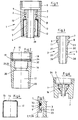
- Fig. 1 shows a hose coupling 1, in which the connecting nut 2 in one piece is trained. This means that the connecting nut 2 as a complete component appropriately inserted nipple 3 receives and supports, without it, additional Components required.
- nipple 3 is equipped with a shoulder 4 as usual is that has a profile 5 that the postponement of not shown here Hose favors.
- the connecting nut 2 is on the opposite side via a thread 6 that the screwing of the component, also not shown here, especially the hand shower allows.
- the nipple 3 consists of the head 7 with the support ring 8, which is itself is supported on the connecting nut 2, and from the already mentioned approach 4 with the Profile 5.
- a groove 9 is formed, in which an O-ring seal only indicated here 10 can be used. This O-ring seal 10 ensures that the coupling space 18 liquid or gas can not escape laterally.
- the support ring 8 forms the lower part 11 of the head 7, which is on the ring projection 20 supports, which is formed on or in the connecting nut 2. This is given the possibility of a hose sitting on the profile 5 of the attachment 4 Arrange so that the not shown here, but via the thread 6 with the Twist hose coupling 1 connected hand shower.
- This twisting of the hand shower is further promoted by that the hose end sitting in the connecting nut 2 or its receiving space 17 is surrounded by a sleeve 12.
- This sleeve 12 has a flanged Edge 13, wherein Fig. 1 and Fig. 4 can be seen that this edge 13 to the approach 4 of the nipple 3 is introduced. So there remains a passage 14, the but after sliding the sleeve 12 onto the neck 4 ensures that the sleeve 12 slips down from approach 4, so that self-assurance is achieved.
- the interior 16 of the connecting nut 2 is, as already mentioned, in the receiving space 17 for the sleeve 12 and the hose end piece, not shown, and in the Coupling space 18 divided.
- the flat seal 19 is arranged in the coupling space 18, which illustrates Fig. 2.
- Fig. 2 also shows that the ring projection 20 on the top 21 a Can have an incline to practically slip the nipple 3 or better to favor the head 7 when inserted into the connecting nut 2.
- This especially trained top 21 also prevents tilting or inclination of the Hose opposite the hand shower and usually hinders an independent Don't twist. It is advantageous if the mutually facing sides 22/23 of support ring 8 and ring projection 20 are formed correspondingly.
- the nipple 3 is inserted from the side 15 into the connecting nut 2. Then the flat seal 19 is placed and the sleeve 12 from below with or inserted without the inserted tube. Then the assembly is already finished. 3 shows that the length of the projection 4 differently shaped tooth projections 26, 27 can be provided. 3 are the first tooth projections 26 equipped with axial flanks 28, while the flanks in the direction of the support ring 8 28 are getting steeper and seen from the top 29 of approach 4. This results in inclined surfaces 30, which are the pushing on of the hose end favor similarly as the flat tooth projections 26, but a retraction significantly complicate or even prevent due to the annular cutting edges 31.
- a sleeve 12 which has a widely flanged edge 13.
- Such a sleeve 12 can Made of sheet metal or a similar material that the turning of the connecting nut 2 compared to the nipple 3 easily.
- FIG. 5 shows a detail in the area of the contact surfaces between the support ring 8 and ring projection 20. It can be seen that here the two parts of nipple 3 and connecting nut 2 have a spherical shape on the facing sides 22/23, so that the Contact surface when turning the connecting nut 2 relative to the nipple 3 on reduce as little as possible.
- the O-ring seal 10 can also be seen here, which is in the groove 9 and which rubs against the wall 33 in order to achieve the necessary here Effect sealing.
- this Flat gasket 19 In the area of the flat seal 19, which is on the support surface 32 supports, however, you want to achieve a flat seal, this Flat gasket 19 here has this shape in a targeted manner so that it extends below the thread 6 to be able to push.
- the connection nut 2 therefore has a corresponding wide recess 34. The same is shown in both FIG. 2 and FIG. 6.
- Fig. 6 additionally shows that there is also the possibility of the head 7 of the nipple 3 overall shape so that it is in the appropriately trained interior 16 fits.
- the flat seal 19 acts as a captive device, whereby naturally by the corresponding shape of the head 7 and also the interior 16 a relatively large contact area between the two components head 7 and connecting nut 2 is created. This can be done by an appropriate one, not here reproduced coating are collected and also in that corresponding Materials are used from which the nipple 3 is made.
- the in Fig. 6 reproduced training is characterized by the fact that it also the highest demands Holds up, for example in the industrial sector.
Abstract
Description
- Fig. 1
- eine Schlauchkupplung im Schnitt,
- Fig. 2
- die Anschlußmutter im Schnitt, mit eingesetzter Flachdichtung,
- Fig. 3
- den Nippel in Längsschnitt,
- Fig. 4
- die Hülse im Längsschnitt,
- Fig. 5
- eine vergrößerte Darstellung des Stützbereiches zwischen Nippelkopf und Anschlußmutter und
- Fig. 6
- eine besondere Formgebung für den Kopf des Nippels.
Claims (11)
- Schlauchkupplung zur Verbindung eines Schlauches mit einem Anschlußschraubteil, insbesondere eines Schlauches mit einer Handbrause, bestehend aus einem Nippel (3) mit zylindrischem, zägezahnähnlich profiliertem Ansatz (4) und gestuftem Kopf (7) mit Stützring (8) und in einer Nut (9) gelagerter O-Ringdichtung (10), einer den Schlauch umgebenden Hülse (12) mit umgebördeltem und das Schlauchende umfassenden Rand (13) und einer die Hülse (12) sowie den von der gegenüberliegenden Seite (15) einführbaren Nippel (3) aufnehmenden Anschlußmutter (2) mit Gewinde (6) und deren Innenraum (16) gegen das Anschlußschraubteil abdichtenden Flachdichtung (19),
dadurch gekennzeichnet,
daß der Stützring (8) vom im Abstand zur O-Ringdichtung (10) ausgebildeten Unterteil (11) des gestuften Kopfes (7) des Nippels (3) gebildet ist und sich direkt auf einen, den Aufnahmeraum (17) für Schlauch und Hülse (12) vom das Gewinde (6) aufweisenden Kopplungsraum (18) trennenden Ringvorsprung (20) der Anschlußmutter (2) abstützt, der in Weiterführung zum Kopplungsraum (18) zurückspringt und die Flachdichtung (19) aufnimmt. - Schlauchkupplung nach Anspruch 1,
dadurch gekennzeichnet,
daß die Anschlußmutter (2) und der Nippel (3) aus einem bezüglich der Eigenschaften korrespondierenden Material hergestellt sind. - Schlauchkupplung nach Anspruch 1,
dadurch gekennzeichnet,
daß der Nippel (3) aus einem reibungsarmen Material besteht oder eine entsprechende Beschichtung aufweist. - Schlauchkupplung nach Anspruch 1 - Anspruch 3,
dadurch gekennzeichnet,
daß die O-Ringdichtung (10) eine reibungsarme Beschichtung aufweist oder entsprechend ausgebildet ist. - Schlauchkupplung nach Anspruch 1 - Anspruch 4,
dadurch gekennzeichnet,
daß das Unterteil (11) des Kopfes (7) und die Oberseite (21) des Ringvorsprunges (20) korrespondierend schräg verlaufend ausgebildet sind. - Schlauchkupplung nach Anspruch 1 - Anspruch 4,
dadurch gekennzeichnet,
daß das Unterteil (11) des Kopfes (7) und der Ringvorsprung (20) auf den einander zugewandten Seiten (22/23) ballig ausgebildet sind. - Schlauchkupplung nach Anspruch 1 - Anspruch 6,
dadurch gekennzeichnet,
daß das Profil (5) auf dem Ansatz (4) des Nippels (3) über seine Länge gesehen verändert, insbesondere mit enger gesetzten Zahnvorsprüngen (26, 27) ausgerüstet ist. - Schlauchkupplung nach Anspruch 1 Anspruch 6,
dadurch gekennzeichnet,
daß das Profil (5) auf dem Ansatz (4) zunächst axiale Flanken (28) und dann schräge, d. h. nach von der Spitze (29) gesehen schräg nach außen laufende Schrägflächen (30) aufweist. - Schlauchkupplung nach Anspruch 1 - Anspruch 8,
dadurch gekennzeichnet,
daß der Rand (13) der Hülse (12) bis an den Ansatz (4) heranreichend ausgebildet ist. - Schlauchkupplung nach Anspruch 1 - Anspruch 9,
dadurch gekennzeichnet,
daß die Abstützfläche (32) für die Flachdichtung (19) im Kopplungsraum (18) bis unter das Gewinde (6) reichend bzw. durch das Gewinde (6) hindurchgezogen ausgebildet ist. - Schlauchkupplung nach Anspruch 1 - Anspruch 10,
dadurch gekennzeichnet,
daß die Wandung (33) des Aufnahmeraumes (17) der Anschlußmutter (2) bis zur Spitze (29) des eingesetzten Nippels (3) mit Ansatz (4) heruntergezogen ausgebildet ist.
Applications Claiming Priority (2)
| Application Number | Priority Date | Filing Date | Title |
|---|---|---|---|
| DE19628917A DE19628917A1 (de) | 1996-07-18 | 1996-07-18 | Verdrehsichere Schlauchkupplung |
| DE19628917 | 1996-07-18 |
Publications (2)
| Publication Number | Publication Date |
|---|---|
| EP0828104A1 true EP0828104A1 (de) | 1998-03-11 |
| EP0828104B1 EP0828104B1 (de) | 2001-09-05 |
Family
ID=7800129
Family Applications (1)
| Application Number | Title | Priority Date | Filing Date |
|---|---|---|---|
| EP97111898A Expired - Lifetime EP0828104B1 (de) | 1996-07-18 | 1997-07-12 | Drehbare Schlauchkupplung |
Country Status (5)
| Country | Link |
|---|---|
| EP (1) | EP0828104B1 (de) |
| AT (1) | ATE205289T1 (de) |
| DE (2) | DE19628917A1 (de) |
| ES (1) | ES2160285T3 (de) |
| PT (1) | PT828104E (de) |
Families Citing this family (5)
| Publication number | Priority date | Publication date | Assignee | Title |
|---|---|---|---|---|
| DE19859315A1 (de) * | 1998-12-22 | 2000-06-29 | Hansgrohe Ag | Brausekombination |
| DE10062696A1 (de) * | 2000-12-15 | 2002-06-20 | Bernhard Wietrzynski | Schraubeinheit |
| DE10240164A1 (de) * | 2002-08-30 | 2004-03-25 | Löffler, Marcus | Mehrfachbrausehalter |
| DE10253736A1 (de) * | 2002-10-16 | 2004-05-13 | Bodedynamic Gmbh | Vorrichtung zur Abdichtung |
| WO2010118441A1 (en) * | 2009-04-07 | 2010-10-14 | Neil Shraga | A hose coupling and protective hose |
Citations (8)
| Publication number | Priority date | Publication date | Assignee | Title |
|---|---|---|---|---|
| DE810452C (de) * | 1948-10-02 | 1951-08-09 | Hans Skodock | Drehbare UEberwurfverschraubung fuer parallelgewellte biegsame Metallrohre mit Draht- oder Bandumflechtung |
| DE851289C (de) * | 1941-04-13 | 1952-10-02 | Busch Jaeger Luedenscheider Me | Verschraubung zum Befestigen von Metallschlaeuchen |
| AU746766A (en) * | 1966-06-27 | 1968-01-04 | Improvements in hose end fittings | |
| DE7626988U1 (de) * | 1976-08-28 | 1976-12-23 | Jurak, Iwan, 7532 Niefern-Oeschelbronn | Drehbare kupplung zwischen einem druckluftschlauch und einem druckluftbetriebenen geraet |
| DE3309936C2 (de) * | 1983-03-19 | 1985-03-28 | Hans Grohe Gmbh & Co Kg, 7622 Schiltach | Nippel zum drehbaren Anschluß eines Schlauches |
| EP0423644A1 (de) * | 1989-10-14 | 1991-04-24 | American Standard Inc. | Verbindungsstück für einen Brausekopf |
| DE9311759U1 (de) * | 1993-08-06 | 1993-11-11 | Kottmann Nachf Gebr Gosla Gmbh | Nippel zum drehbaren Anschluß eines Schlauches |
| EP0728978A1 (de) * | 1995-02-21 | 1996-08-28 | OLDOPLAST KUNSTSTOFFPROFILE GMBH & CO. KG | Sanitärschlauch mit drehbarer Kupplung eines Anschlussstückes |
-
1996
- 1996-07-18 DE DE19628917A patent/DE19628917A1/de not_active Ceased
-
1997
- 1997-07-12 AT AT97111898T patent/ATE205289T1/de not_active IP Right Cessation
- 1997-07-12 ES ES97111898T patent/ES2160285T3/es not_active Expired - Lifetime
- 1997-07-12 EP EP97111898A patent/EP0828104B1/de not_active Expired - Lifetime
- 1997-07-12 PT PT97111898T patent/PT828104E/pt unknown
- 1997-07-12 DE DE59704517T patent/DE59704517D1/de not_active Expired - Fee Related
Patent Citations (8)
| Publication number | Priority date | Publication date | Assignee | Title |
|---|---|---|---|---|
| DE851289C (de) * | 1941-04-13 | 1952-10-02 | Busch Jaeger Luedenscheider Me | Verschraubung zum Befestigen von Metallschlaeuchen |
| DE810452C (de) * | 1948-10-02 | 1951-08-09 | Hans Skodock | Drehbare UEberwurfverschraubung fuer parallelgewellte biegsame Metallrohre mit Draht- oder Bandumflechtung |
| AU746766A (en) * | 1966-06-27 | 1968-01-04 | Improvements in hose end fittings | |
| DE7626988U1 (de) * | 1976-08-28 | 1976-12-23 | Jurak, Iwan, 7532 Niefern-Oeschelbronn | Drehbare kupplung zwischen einem druckluftschlauch und einem druckluftbetriebenen geraet |
| DE3309936C2 (de) * | 1983-03-19 | 1985-03-28 | Hans Grohe Gmbh & Co Kg, 7622 Schiltach | Nippel zum drehbaren Anschluß eines Schlauches |
| EP0423644A1 (de) * | 1989-10-14 | 1991-04-24 | American Standard Inc. | Verbindungsstück für einen Brausekopf |
| DE9311759U1 (de) * | 1993-08-06 | 1993-11-11 | Kottmann Nachf Gebr Gosla Gmbh | Nippel zum drehbaren Anschluß eines Schlauches |
| EP0728978A1 (de) * | 1995-02-21 | 1996-08-28 | OLDOPLAST KUNSTSTOFFPROFILE GMBH & CO. KG | Sanitärschlauch mit drehbarer Kupplung eines Anschlussstückes |
Also Published As
| Publication number | Publication date |
|---|---|
| PT828104E (pt) | 2002-02-28 |
| ES2160285T3 (es) | 2001-11-01 |
| ATE205289T1 (de) | 2001-09-15 |
| EP0828104B1 (de) | 2001-09-05 |
| DE59704517D1 (de) | 2001-10-11 |
| DE19628917A1 (de) | 1998-01-22 |
Similar Documents
| Publication | Publication Date | Title |
|---|---|---|
| DE2308820C3 (de) | Axial bewegliche Lippendichtung für die Keilwellennabe einer Gelenkwelle | |
| DE69722576T2 (de) | Befestigungseinrichtung für eine Lagereinheit einer Radnabe in einer Radaufhängung eines Kraftfahrzeugs | |
| DD298018A5 (de) | Stopfbuchsenpackung fuer dicht verschliessbare verbindungen | |
| DE3218751A1 (de) | Dichtungseinrichtung | |
| DE4136704A1 (de) | Abdichtungsvorrichtung zum einbau in lager, insbesondere radiallager | |
| DE10164598B4 (de) | Anschlussvorrichtung zum Anschließen von Anschlag- oder Verzurrmitteln | |
| DE2155998C3 (de) | Montagebuchse zum Einführen eines mit Kolbenringen bestickten Kolbens in eine Zylinderbohrung | |
| EP0828104B1 (de) | Drehbare Schlauchkupplung | |
| DE102006058945A1 (de) | Dichtungselement für rotierbare Teile mit Traktrix-Form | |
| DE102005017746B4 (de) | Einbauanordnung für Antriebswellen in Kreuzgelenkgabeln | |
| DE3612420C2 (de) | ||
| DE3509064A1 (de) | Fuehrungswagen fuer eine lamellenjalousie | |
| DE19963368A1 (de) | Schnellkupplung für Schläuche oder Rohrleitungen mit erhöhtem Diffusionswiderstand | |
| DE102004018054B4 (de) | Dichtungsbalg | |
| DE8232482U1 (de) | Scheibenwischerschwenkvorrichtung | |
| DE10329433B4 (de) | Lageranordnung mit einem Lagerträger und wenigstens einem Lager | |
| EP0879982B1 (de) | Schlauchkupplung | |
| DE3306788A1 (de) | Auslauf fuer sanitaerbauteile, wie fuer hand- und spuelbecken, badewannen od. dgl. | |
| DE1725025C3 (de) | Lager für eine Bremsnockenwelle | |
| EP0239869A1 (de) | Bolzen zum Arretieren einer in einer Führungsbohrung längsverschieblichen Stange | |
| DE10148461A1 (de) | Kugelumlaufspindel mit einem Kugelkäfig | |
| DE2628727A1 (de) | Steckmuffen-verbindung | |
| DE3128133C2 (de) | Verschlußklappe für Luftleitungen | |
| DE2540381B2 (de) | Wellendichtung | |
| WO2007016980A1 (de) | Elastomer-wellendichtring |
Legal Events
| Date | Code | Title | Description |
|---|---|---|---|
| PUAI | Public reference made under article 153(3) epc to a published international application that has entered the european phase |
Free format text: ORIGINAL CODE: 0009012 |
|
| AK | Designated contracting states |
Kind code of ref document: A1 Designated state(s): AT BE CH DE DK ES FI FR GB GR IE IT LI LU MC NL PT SE |
|
| AX | Request for extension of the european patent |
Free format text: AL PAYMENT 970712;LT PAYMENT 970712;LV PAYMENT 970712;SI PAYMENT 970712 |
|
| 17P | Request for examination filed |
Effective date: 19980328 |
|
| AKX | Designation fees paid |
Free format text: AT BE CH DE DK ES FI FR GB GR IE IT LI LU MC NL PT SE |
|
| AXX | Extension fees paid |
Free format text: AL PAYMENT 970712;LT PAYMENT 970712;LV PAYMENT 970712;SI PAYMENT 970712 |
|
| RBV | Designated contracting states (corrected) |
Designated state(s): AT BE CH DE DK ES FI FR GB GR IE IT LI LU MC NL PT SE |
|
| 17Q | First examination report despatched |
Effective date: 19991116 |
|
| GRAG | Despatch of communication of intention to grant |
Free format text: ORIGINAL CODE: EPIDOS AGRA |
|
| GRAG | Despatch of communication of intention to grant |
Free format text: ORIGINAL CODE: EPIDOS AGRA |
|
| GRAH | Despatch of communication of intention to grant a patent |
Free format text: ORIGINAL CODE: EPIDOS IGRA |
|
| GRAH | Despatch of communication of intention to grant a patent |
Free format text: ORIGINAL CODE: EPIDOS IGRA |
|
| GRAA | (expected) grant |
Free format text: ORIGINAL CODE: 0009210 |
|
| AK | Designated contracting states |
Kind code of ref document: B1 Designated state(s): AT BE CH DE DK ES FI FR GB GR IE IT LI LU MC NL PT SE |
|
| AX | Request for extension of the european patent |
Free format text: AL PAYMENT 19970712;LT PAYMENT 19970712;LV PAYMENT 19970712;SI PAYMENT 19970712 |
|
| LTIE | Lt: invalidation of european patent or patent extension | ||
| PG25 | Lapsed in a contracting state [announced via postgrant information from national office to epo] |
Ref country code: IE Free format text: LAPSE BECAUSE OF FAILURE TO SUBMIT A TRANSLATION OF THE DESCRIPTION OR TO PAY THE FEE WITHIN THE PRESCRIBED TIME-LIMIT Effective date: 20010905 Ref country code: GB Free format text: LAPSE BECAUSE OF FAILURE TO SUBMIT A TRANSLATION OF THE DESCRIPTION OR TO PAY THE FEE WITHIN THE PRESCRIBED TIME-LIMIT Effective date: 20010905 Ref country code: FI Free format text: LAPSE BECAUSE OF FAILURE TO SUBMIT A TRANSLATION OF THE DESCRIPTION OR TO PAY THE FEE WITHIN THE PRESCRIBED TIME-LIMIT Effective date: 20010905 |
|
| REF | Corresponds to: |
Ref document number: 205289 Country of ref document: AT Date of ref document: 20010915 Kind code of ref document: T |
|
| REG | Reference to a national code |
Ref country code: CH Ref legal event code: NV Representative=s name: SCHMAUDER & PARTNER AG PATENTANWALTSBUERO Ref country code: CH Ref legal event code: EP |
|
| REF | Corresponds to: |
Ref document number: 59704517 Country of ref document: DE Date of ref document: 20011011 |
|
| REG | Reference to a national code |
Ref country code: IE Ref legal event code: FG4D Free format text: GERMAN |
|
| REG | Reference to a national code |
Ref country code: ES Ref legal event code: FG2A Ref document number: 2160285 Country of ref document: ES Kind code of ref document: T3 |
|
| PG25 | Lapsed in a contracting state [announced via postgrant information from national office to epo] |
Ref country code: SE Free format text: LAPSE BECAUSE OF FAILURE TO SUBMIT A TRANSLATION OF THE DESCRIPTION OR TO PAY THE FEE WITHIN THE PRESCRIBED TIME-LIMIT Effective date: 20011205 Ref country code: DK Free format text: LAPSE BECAUSE OF FAILURE TO SUBMIT A TRANSLATION OF THE DESCRIPTION OR TO PAY THE FEE WITHIN THE PRESCRIBED TIME-LIMIT Effective date: 20011205 |
|
| PG25 | Lapsed in a contracting state [announced via postgrant information from national office to epo] |
Ref country code: GR Free format text: LAPSE BECAUSE OF FAILURE TO SUBMIT A TRANSLATION OF THE DESCRIPTION OR TO PAY THE FEE WITHIN THE PRESCRIBED TIME-LIMIT Effective date: 20011207 |
|
| ET | Fr: translation filed | ||
| REG | Reference to a national code |
Ref country code: PT Ref legal event code: SC4A Free format text: AVAILABILITY OF NATIONAL TRANSLATION Effective date: 20011127 |
|
| GBV | Gb: ep patent (uk) treated as always having been void in accordance with gb section 77(7)/1977 [no translation filed] |
Effective date: 20010905 |
|
| REG | Reference to a national code |
Ref country code: IE Ref legal event code: FD4D |
|
| PG25 | Lapsed in a contracting state [announced via postgrant information from national office to epo] |
Ref country code: LU Free format text: LAPSE BECAUSE OF NON-PAYMENT OF DUE FEES Effective date: 20020712 Ref country code: AT Free format text: LAPSE BECAUSE OF NON-PAYMENT OF DUE FEES Effective date: 20020712 |
|
| PG25 | Lapsed in a contracting state [announced via postgrant information from national office to epo] |
Ref country code: ES Free format text: LAPSE BECAUSE OF NON-PAYMENT OF DUE FEES Effective date: 20020713 |
|
| PLBE | No opposition filed within time limit |
Free format text: ORIGINAL CODE: 0009261 |
|
| STAA | Information on the status of an ep patent application or granted ep patent |
Free format text: STATUS: NO OPPOSITION FILED WITHIN TIME LIMIT |
|
| PG25 | Lapsed in a contracting state [announced via postgrant information from national office to epo] |
Ref country code: LI Free format text: LAPSE BECAUSE OF NON-PAYMENT OF DUE FEES Effective date: 20020731 Ref country code: CH Free format text: LAPSE BECAUSE OF NON-PAYMENT OF DUE FEES Effective date: 20020731 Ref country code: BE Free format text: LAPSE BECAUSE OF NON-PAYMENT OF DUE FEES Effective date: 20020731 |
|
| 26N | No opposition filed | ||
| BERE | Be: lapsed |
Owner name: FRANZ *SCHEFFER OHG Effective date: 20020731 |
|
| PG25 | Lapsed in a contracting state [announced via postgrant information from national office to epo] |
Ref country code: PT Free format text: LAPSE BECAUSE OF NON-PAYMENT OF DUE FEES Effective date: 20030131 |
|
| PG25 | Lapsed in a contracting state [announced via postgrant information from national office to epo] |
Ref country code: NL Free format text: LAPSE BECAUSE OF NON-PAYMENT OF DUE FEES Effective date: 20030201 Ref country code: MC Free format text: LAPSE BECAUSE OF NON-PAYMENT OF DUE FEES Effective date: 20030201 |
|
| REG | Reference to a national code |
Ref country code: CH Ref legal event code: PL |
|
| PG25 | Lapsed in a contracting state [announced via postgrant information from national office to epo] |
Ref country code: FR Free format text: LAPSE BECAUSE OF NON-PAYMENT OF DUE FEES Effective date: 20030331 |
|
| NLV4 | Nl: lapsed or anulled due to non-payment of the annual fee |
Effective date: 20030201 |
|
| REG | Reference to a national code |
Ref country code: PT Ref legal event code: MM4A Free format text: LAPSE DUE TO NON-PAYMENT OF FEES Effective date: 20030131 |
|
| REG | Reference to a national code |
Ref country code: FR Ref legal event code: ST |
|
| REG | Reference to a national code |
Ref country code: ES Ref legal event code: FD2A Effective date: 20030811 |
|
| PG25 | Lapsed in a contracting state [announced via postgrant information from national office to epo] |
Ref country code: IT Free format text: LAPSE BECAUSE OF NON-PAYMENT OF DUE FEES Effective date: 20050712 |
|
| PGFP | Annual fee paid to national office [announced via postgrant information from national office to epo] |
Ref country code: DE Payment date: 20070705 Year of fee payment: 11 |
|
| PG25 | Lapsed in a contracting state [announced via postgrant information from national office to epo] |
Ref country code: DE Free format text: LAPSE BECAUSE OF NON-PAYMENT OF DUE FEES Effective date: 20090203 |