EP0826856B1 - Kopplungseinrichtung für ein Schloss, insbesondere ein Türschloss eines Kraftfahrzeuges - Google Patents
Kopplungseinrichtung für ein Schloss, insbesondere ein Türschloss eines Kraftfahrzeuges Download PDFInfo
- Publication number
- EP0826856B1 EP0826856B1 EP97113367A EP97113367A EP0826856B1 EP 0826856 B1 EP0826856 B1 EP 0826856B1 EP 97113367 A EP97113367 A EP 97113367A EP 97113367 A EP97113367 A EP 97113367A EP 0826856 B1 EP0826856 B1 EP 0826856B1
- Authority
- EP
- European Patent Office
- Prior art keywords
- lock
- coupling device
- handle
- coupling
- recess
- Prior art date
- Legal status (The legal status is an assumption and is not a legal conclusion. Google has not performed a legal analysis and makes no representation as to the accuracy of the status listed.)
- Expired - Lifetime
Links
Images
Classifications
-
- E—FIXED CONSTRUCTIONS
- E05—LOCKS; KEYS; WINDOW OR DOOR FITTINGS; SAFES
- E05B—LOCKS; ACCESSORIES THEREFOR; HANDCUFFS
- E05B77/00—Vehicle locks characterised by special functions or purposes
- E05B77/22—Functions related to actuation of locks from the passenger compartment of the vehicle
- E05B77/24—Functions related to actuation of locks from the passenger compartment of the vehicle preventing use of an inner door handle, sill button, lock knob or the like
- E05B77/28—Functions related to actuation of locks from the passenger compartment of the vehicle preventing use of an inner door handle, sill button, lock knob or the like for anti-theft purposes, e.g. double-locking or super-locking
-
- E—FIXED CONSTRUCTIONS
- E05—LOCKS; KEYS; WINDOW OR DOOR FITTINGS; SAFES
- E05B—LOCKS; ACCESSORIES THEREFOR; HANDCUFFS
- E05B81/00—Power-actuated vehicle locks
- E05B81/02—Power-actuated vehicle locks characterised by the type of actuators used
- E05B81/04—Electrical
- E05B81/06—Electrical using rotary motors
Definitions
- the invention relates to a coupling device for a lock, in particular a door lock of a motor vehicle, according to the features of Preamble of claim 1.
- a coupling device for a Lock in particular a door lock of a motor vehicle, described. It has two elements, one between them Movable in two positions by an actuator Coupling element is arranged, one element on a Lock element works or is a lock element and that at least one other element depending on the actuation at least one handle can be actuated or by this itself is operated, and wherein the at least one element has a recess into which a pin is in one position of the coupling element engages.
- DE 195 47 729.4 is a coupling device for a lock known, which has at least two elements, between which one in Coupling element arranged in two positions by an adjusting device is, with an element acting on a lock element or a
- the lock element itself is dependent on at least one other element the actuation of a handle can be actuated or by this is operated itself.
- the two elements (pawl and coupling element) have stop surfaces, the coupling member between two positions is movable by an actuator. Is the coupling link in the Area of the stop surfaces, an actuation of the handle on the Pawl are transmitted so that the catch is locked out of it Position is released and the door can be opened.
- the invention is therefore based on the object of such a coupling device for a lock while maintaining the functionality in terms of its manufacturing costs and long-term reliability to improve.
- the introduction of a recess in at least one element of the coupling device has the advantage that it is easy to manufacture of the element can be introduced or subsequently by material-removing Processing can be done. This also applies to the statics of the element is not affected. It is also advantageous that the pin of the coupling member can be produced from solid material, only the Tenon takes over the coupling function and the movement, in particular a rotational movement of the pin on the coupling member, which is advantageous Is designed as an elongated lever. Moreover the pin on the one hand the recess of the one element and on the other hand, be adapted to the contours of the further element, so that little or no play between the elements during the coupling process prevails and the largest possible areas of the elements of the pin be covered.
- the at least one element is one Pawl locking pawl. Because the pawl has the recess has and acts directly on the rotary latch, advantageously omitted additional force-transmitting elements that increase component costs would.
- the at least one element is a release lever, depending on the actuation of a handle or of this can be actuated itself. If the release lever has the recess, is this not available in the pawl, so that an alternative Construction is available, for example with the already existing Locks in which the pawl has no recess, retrofitted with the coupling device according to the invention can be. Connection elements are then on the single trigger lever such as Bowden cables, rods or the like arranged to one or more handles (inside door handle and Outside door handle).
- two release levers are further elements each provided with a recess. These recesses are then congruent, so that each release lever with a Handle (e.g. a release lever with the inside door handle) further release lever is connected to the outer door handle), so that the Lock can be operated independently of these handles can.
- the pawl has no recess.
- two release levers are further elements provided without recess, whereby the already described Operation of the lock independently of the two handles can be performed, with the recess on the pawl is provided.
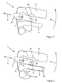
- Figure 1 shows a coupling device 1 for a lock, in which it is preferably around a door lock of a motor vehicle, in particular of a passenger car.
- the castle has usual Lock elements such as locking wedge, rotary latch (which are not shown) as well a pawl 2, which holds the catch in its locked position. In the door is locked in this position.
- Lock elements such as locking wedge, rotary latch (which are not shown) as well a pawl 2, which holds the catch in its locked position. In the door is locked in this position.
- Lock elements such as locking wedge, rotary latch (which are not shown) as well a pawl 2, which holds the catch in its locked position. In the door is locked in this position.
- Lock elements are known and therefore need not be explained further here, the Coupling device according to the invention in a variety of lock designs is applicable.
- the pawl 2 as the one element is a release lever as another element 3 assigned, the pawl 2 and the trigger lever 3 are movable about a common pivot point 4.
- the trigger lever 3 has approximately a T-shape, with one short end of the pivot point 4 and at the other short end a linkage area 5 are arranged.
- Bowden cables engage in the articulation area 5, Linkage or the like to at least one handle or several manipulations.
- the actuator which is not shown, and can the coupling member 6 and thus the pin 7 perform at least one linear movement 8 let the pin 7 between two positions (end positions) to move.
- the coupling member 6 and thus the pin 7 performs a rotary movement 9, which is from an actuation a handle is triggered.
- the Pawl 2 has a recess 10 which roughly the contours of the pin 7 corresponds. Other geometrical contours are a matter of course possible.
- the pin 7 is now from the actuating device, not shown between the one position DS in the second position shown Moveable and back. The mode of operation will be explained later using the Figure 2 explains.
- Figure 2 shows a further embodiment of the coupling device 1, wherein in addition to the trigger lever 3 with a further trigger lever 11 a further articulation area 12 also mounted around the pivot point 4 is available.
- a preferred embodiment is that on the Articulation area 5 an outer door handle and on the other articulation area 12 an inner door handle (or vice versa) is connected. It is believed, that a mechanical movement of a handle is also a mechanical one Movement of the trigger lever 3 or 11 results.
- the actuated release lever 3 or 11 rotates the pin 7 in the direction of the rotational movement 9 in the recess 10 in the pawl 2, so that it is not deflected around the pivot point 4 and in their shown position remains.
- the pawl 2 locks in this position the catch, so that the handle and thus the actuated release lever one Performs idle stroke and the door remains closed. This is particularly true in an anti-theft position.
- the actuating device in particular is electromechanical Actuators such as electromagnets, electric motors with downstream transmission or reduction gear, stepper motors or the like are used, in particular in their End positions remain without current, but also pneumatic, hydraulic or other control devices are conceivable.
- the release lever and possibly the pawl as a circular disc or form circular disk and this with openings (for example, holes) to be provided, the openings in the sense the recess 10 described are arranged. In these openings an elongated pin can then be extended and retracted along its longitudinal axis become.
Landscapes
- Lock And Its Accessories (AREA)
Description
- Figur 1:
- eine erste Ausführungsform einer Kopplungseinrichtung,
- Figur 2:
- eine zweite Ausführungsform einer Kopplungseinrichtung.
Claims (5)
- Kopplungseinrichtung (1) für ein Schloss, insbesondere ein Türschloss eines Kraftfahrzeuges, mit zumindest zwei Elementen, zwischen denen ein in zwei Positionen von einer Stelleinrichtung bewegbares Koppelglied (6) angeordnet ist, wobei ein Element auf ein Schlosselement wirkt oder ein Schlosselement ist und das zumindest eine weitere Element in Abhängigkeit der Betätigung zumindest einer Handhabe betätigbar ist oder von dieser selbst betätigt wird, und wobei das zumindest eine Element eine Ausnehmung (10) aufweist, in die in einer Position ein Zapfen (7) des Koppelgliedes (6) eingreift, dadurch gekennzeichnet, dass die zumindest zwei Elemente sowie das Koppelglied (6) um einen gemeinsamen Drehpunkt (4) herum bewegbar sind.
- Kopplungseinrichtung (1) nach Anspruch 1, dadurch gekennzeichnet, daß das zumindest eine Element eine eine Drehfalle arretierende Sperrklinke (2) ist.
- Kopplungseinrichtung (1) nach Anspruch 1, dadurch gekennzeichnet, daß das zumindest eine Element ein Auslösehebel (3) ist, der in Abhängigkeit der Betätigung einer Handhabe betätigbar ist oder von dieser selbst betätigt wird.
- Kopplungseinrichtung (1) nach Anspruch 3, dadurch gekennzeichnet, daß als weitere Elemente zwei Auslösehebel jeweils mit einer Ausnehmung, die sich überdecken, vorgesehen sind.
- Kopplungseinrichtung (1) nach Anspruch 1, dadurch gekennzeichnet, daß als weitere Elemente zwei Auslösehebel (3, 11) ohne Ausnehmung vorgesehen sind.
Applications Claiming Priority (2)
| Application Number | Priority Date | Filing Date | Title |
|---|---|---|---|
| DE19635415A DE19635415C2 (de) | 1996-08-31 | 1996-08-31 | Kopplungseinrichtung für ein Schloß, insbesondere ein Türschloß eines Kraftfahrzeuges |
| DE19635415 | 1996-08-31 |
Publications (3)
| Publication Number | Publication Date |
|---|---|
| EP0826856A2 EP0826856A2 (de) | 1998-03-04 |
| EP0826856A3 EP0826856A3 (de) | 1999-11-17 |
| EP0826856B1 true EP0826856B1 (de) | 2003-10-22 |
Family
ID=7804309
Family Applications (1)
| Application Number | Title | Priority Date | Filing Date |
|---|---|---|---|
| EP97113367A Expired - Lifetime EP0826856B1 (de) | 1996-08-31 | 1997-08-02 | Kopplungseinrichtung für ein Schloss, insbesondere ein Türschloss eines Kraftfahrzeuges |
Country Status (2)
| Country | Link |
|---|---|
| EP (1) | EP0826856B1 (de) |
| DE (2) | DE19635415C2 (de) |
Families Citing this family (4)
| Publication number | Priority date | Publication date | Assignee | Title |
|---|---|---|---|---|
| US6082158A (en) * | 1996-12-21 | 2000-07-04 | Mannesmann Vdo Ag | Closing device |
| DE19755207A1 (de) | 1996-12-21 | 1998-06-25 | Mannesmann Vdo Ag | Schließeinrichtung |
| DE19956674B4 (de) | 1999-11-25 | 2005-12-01 | Siemens Ag | Zentralverriegelungsantrieb |
| JP4342502B2 (ja) * | 2004-11-17 | 2009-10-14 | アイシン精機株式会社 | ドアロックチャイルドプロテクタ装置 |
Family Cites Families (3)
| Publication number | Priority date | Publication date | Assignee | Title |
|---|---|---|---|---|
| GB2073299B (en) * | 1980-03-27 | 1983-09-21 | Mitsui Mining & Smelting Co | Automobile door locking mechanism |
| US4492395A (en) * | 1981-08-07 | 1985-01-08 | Mitsui Kinzoku Kogyo K.K. | Automotive door latch system including a childproofing mechanism |
| DE4433994C1 (de) * | 1994-09-23 | 1996-03-14 | Kiekert Ag | Kraftfahrzeug-Türverschluß mit reversierbarem Zentralverriegelungsantrieb |
-
1996
- 1996-08-31 DE DE19635415A patent/DE19635415C2/de not_active Expired - Fee Related
-
1997
- 1997-08-02 EP EP97113367A patent/EP0826856B1/de not_active Expired - Lifetime
- 1997-08-02 DE DE59710877T patent/DE59710877D1/de not_active Expired - Fee Related
Also Published As
| Publication number | Publication date |
|---|---|
| EP0826856A3 (de) | 1999-11-17 |
| EP0826856A2 (de) | 1998-03-04 |
| DE19635415A1 (de) | 1998-03-05 |
| DE19635415C2 (de) | 2001-02-15 |
| DE59710877D1 (de) | 2003-11-27 |
Similar Documents
| Publication | Publication Date | Title |
|---|---|---|
| EP0826855B1 (de) | Schloss, insbesondere für Fahrzeugtüren oder dergleichen | |
| DE19702420B4 (de) | Steuervorrichtung für einen Verschluß, insbesondere von Kraftfahrzeugtüren | |
| DE19706952A1 (de) | Schmutzfreier Öffnungsgriff für Heckklappen von Fahrzeugen | |
| DE10046189B4 (de) | Schließeinrichtung für eine Kraftfahrzeugtür | |
| DE19755207A1 (de) | Schließeinrichtung | |
| DE4444581C2 (de) | Antidiebstahlsmechanismus für Fahrzeugtürschlösser | |
| DE19626745C1 (de) | Selbstverriegelndes Panikschloß | |
| DE102018100301A1 (de) | Schließsystem | |
| DE4005641C2 (de) | ||
| EP2799649B1 (de) | Schlossanordnung für Außentüren von Fahrzeugen, insbesondere von Schienenfahrzeugen, Außentür mit einer solchen Schlossanordnung sowie Schienenfahrzeug mit einer solchen Außentür | |
| DE102013000286A1 (de) | Türschlossvorrichtung für eine Tür mit mindestens einem Türflügel | |
| DE19534609C2 (de) | Selbstverriegelndes Motorschloss | |
| EP2520746B1 (de) | Elektrisch betätigbares Schloss | |
| DE19739340A1 (de) | Elektrisch betätigbares Schloß | |
| WO2016134696A1 (de) | Kraftfahrzeugtürverschluss | |
| DE19635415C2 (de) | Kopplungseinrichtung für ein Schloß, insbesondere ein Türschloß eines Kraftfahrzeuges | |
| DE19650928C2 (de) | Türschloß für ein Kraftfahrzeug | |
| DE4202698C2 (de) | Verschluß für Türen, Hauben o. dgl., insbesondere von Fahrzeugen, wie Kraftfahrzeugen | |
| EP1683936B1 (de) | Schloss mit Falle und Fallenantrieb | |
| AT409020B (de) | Mehrriegelverschluss | |
| EP1617018B1 (de) | Elektromechanisches Türschloss | |
| EP1191171A2 (de) | Kupplungsvorrichtung für Türverriegelungsanlagen | |
| DE10151870A1 (de) | Vorrichtung zur Betätigung eines Verschlusses von Türen oder Klappen, insbesondere an Fahrzeugen | |
| EP0942123A1 (de) | Vorrichtung zum Verriegeln einer Abdeckung nach Art einer Karosseriehaube eines Kraftfahrzeugs | |
| EP1317597B1 (de) | Schliesseinrichtung für ein fahrzeug |
Legal Events
| Date | Code | Title | Description |
|---|---|---|---|
| PUAI | Public reference made under article 153(3) epc to a published international application that has entered the european phase |
Free format text: ORIGINAL CODE: 0009012 |
|
| AK | Designated contracting states |
Kind code of ref document: A2 Designated state(s): DE FR GB |
|
| AX | Request for extension of the european patent |
Free format text: AL;LT;LV;RO;SI |
|
| PUAL | Search report despatched |
Free format text: ORIGINAL CODE: 0009013 |
|
| AK | Designated contracting states |
Kind code of ref document: A3 Designated state(s): AT BE CH DE DK ES FI FR GB GR IE IT LI LU MC NL PT SE |
|
| AX | Request for extension of the european patent |
Free format text: AL;LT;LV;RO;SI |
|
| 17P | Request for examination filed |
Effective date: 19991201 |
|
| AKX | Designation fees paid |
Free format text: DE FR GB |
|
| RAP1 | Party data changed (applicant data changed or rights of an application transferred) |
Owner name: SIEMENS AKTIENGESELLSCHAFT |
|
| 17Q | First examination report despatched |
Effective date: 20011219 |
|
| GRAH | Despatch of communication of intention to grant a patent |
Free format text: ORIGINAL CODE: EPIDOS IGRA |
|
| GRAS | Grant fee paid |
Free format text: ORIGINAL CODE: EPIDOSNIGR3 |
|
| GRAA | (expected) grant |
Free format text: ORIGINAL CODE: 0009210 |
|
| AK | Designated contracting states |
Kind code of ref document: B1 Designated state(s): DE FR GB |
|
| REG | Reference to a national code |
Ref country code: GB Ref legal event code: FG4D Free format text: NOT ENGLISH |
|
| REF | Corresponds to: |
Ref document number: 59710877 Country of ref document: DE Date of ref document: 20031127 Kind code of ref document: P |
|
| GBT | Gb: translation of ep patent filed (gb section 77(6)(a)/1977) |
Effective date: 20040106 |
|
| ET | Fr: translation filed | ||
| PG25 | Lapsed in a contracting state [announced via postgrant information from national office to epo] |
Ref country code: GB Free format text: LAPSE BECAUSE OF NON-PAYMENT OF DUE FEES Effective date: 20040802 |
|
| PLBE | No opposition filed within time limit |
Free format text: ORIGINAL CODE: 0009261 |
|
| STAA | Information on the status of an ep patent application or granted ep patent |
Free format text: STATUS: NO OPPOSITION FILED WITHIN TIME LIMIT |
|
| 26N | No opposition filed |
Effective date: 20040723 |
|
| PG25 | Lapsed in a contracting state [announced via postgrant information from national office to epo] |
Ref country code: DE Free format text: LAPSE BECAUSE OF NON-PAYMENT OF DUE FEES Effective date: 20050301 |
|
| GBPC | Gb: european patent ceased through non-payment of renewal fee |
Effective date: 20040802 |
|
| PG25 | Lapsed in a contracting state [announced via postgrant information from national office to epo] |
Ref country code: FR Free format text: LAPSE BECAUSE OF NON-PAYMENT OF DUE FEES Effective date: 20050429 |
|
| REG | Reference to a national code |
Ref country code: FR Ref legal event code: ST |