EP0825136B1 - Vorrichtung zum Transport, Speichern und Verteilen von Gütern - Google Patents
Vorrichtung zum Transport, Speichern und Verteilen von Gütern Download PDFInfo
- Publication number
- EP0825136B1 EP0825136B1 EP97114074A EP97114074A EP0825136B1 EP 0825136 B1 EP0825136 B1 EP 0825136B1 EP 97114074 A EP97114074 A EP 97114074A EP 97114074 A EP97114074 A EP 97114074A EP 0825136 B1 EP0825136 B1 EP 0825136B1
- Authority
- EP
- European Patent Office
- Prior art keywords
- coupling arrangement
- transporting
- drawing means
- rotating
- transport
- Prior art date
- Legal status (The legal status is an assumption and is not a legal conclusion. Google has not performed a legal analysis and makes no representation as to the accuracy of the status listed.)
- Expired - Lifetime
Links
Images

Classifications
-
- B—PERFORMING OPERATIONS; TRANSPORTING
- B65—CONVEYING; PACKING; STORING; HANDLING THIN OR FILAMENTARY MATERIAL
- B65G—TRANSPORT OR STORAGE DEVICES, e.g. CONVEYORS FOR LOADING OR TIPPING, SHOP CONVEYOR SYSTEMS OR PNEUMATIC TUBE CONVEYORS
- B65G19/00—Conveyors comprising an impeller or a series of impellers carried by an endless traction element and arranged to move articles or materials over a supporting surface or underlying material, e.g. endless scraper conveyors
- B65G19/02—Conveyors comprising an impeller or a series of impellers carried by an endless traction element and arranged to move articles or materials over a supporting surface or underlying material, e.g. endless scraper conveyors for articles, e.g. for containers
- B65G19/025—Conveyors comprising an impeller or a series of impellers carried by an endless traction element and arranged to move articles or materials over a supporting surface or underlying material, e.g. endless scraper conveyors for articles, e.g. for containers for suspended articles
Definitions
- the invention relates to a device for transporting, storing and distributing Goods according to the preamble of claim 1.
- the coupling arrangement is constantly in engagement with the traction means, which results in a very low-wear operation.
- the rotating movement of the coupling arrangement is blocked, so that the coupling arrangement acts like a driver. If the transport means runs against a stop with the coupling arrangement, the blocking is released, the coupling arrangement executes a rotating movement and the transport means is thus decoupled from the traction means.
- the stops can be swung in and out at loading or work stations and at the rear of the means of transport, so that the following transport container is disengaged when moving onto a standing transport container.
- the coupling arrangement is designed as a pinion that is constantly in engagement with a chain as a traction means.
- the blocking and release of the rotating movement of the pinion and thus the coupling and uncoupling to the traction means is realized by means of a slip clutch (DE-AS 1 192 103, DE-AS 1 289 781, DE-OS 2 306 712).
- a disadvantage of the known solutions is that the inward and outward transfer of the goods into the containers and other movements of the goods or containers, such as rotating and swiveling movements, can only be achieved with the aid of complex separate drives.
- the invention is therefore based on the object of a device according to the The preamble of claim 1 to create, with little equipment Effort tipping, swiveling or rotating movements of the containers of the means of transport or goods entry and / or exit movements.
- the coupling arrangement is advantageously a stored and wheel coupled to the traction means in a non-positive or positive manner.
- the coupling arrangement detects Claim 4 wheels on which a force or with the traction endless coupling element in positive engagement, e.g. Timing belt or Chain, running. This increases the coupling surface, so that higher forces can be transferred.
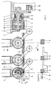
- a toothed disc 3 is rotatably mounted on a guided carrier 1 as a coupling arrangement on an axis 2 by means of a roller or slide bearing 4.
- the toothed pulley is in engagement with a toothed belt 5 as a traction means and is connected axially to the free hub 6 of a spring band coupling.
- Their fixed hub 7 is rigidly attached to the carrier.
- the spring band 8 of the clutch leaves the rotation of the free hub only in one direction to.
- the opposite direction of rotation is blocked as long as a switching cam 9 is not actuated.
- toothed belt 5 moves in the locked direction of rotation 17, it takes over the locked Toothed washer 3 with the carrier 1. If the switch cam 9 during transport bumps against the 1st surface 10 of a stop 14, the free hub is also in Reverse sense of rotation released and the toothed disc 3 begins to rotate. The carrier remains stand on the second stop surface 11, the toothed belt 5 continues to run.
- a stop 12 which moves with the support 1 and is laterally offset from the stop 14
- this arrangement can transport and transport any number of carrier systems individually can be positioned anywhere. Further transport takes place by withdrawing the Stop 14, whereby the switching cam moves back into the locked position. With the synchronous rotation of the toothed pulley is stopped and the carrier 1 transported. As a result, stop 12 also gives the following switching cams free, whereby the next carrier 13 is delayed in the direction of the stop 14 in motion puts
- stop 14 can be brought back in time Positioned to stop carrier 14.
- a short toothed belt can be used instead of a toothed pulley for higher power transmission or several tooth lock washers are used.
- timing belts can be aligned or - to achieve more compact Dimensions - offset.
- a tour of the Transport is carried out via appropriate guide elements.
- Fig. 3 the possible principle of a large letter distribution system is shown.
- the rotating traction device (chain / toothed belt) transports guided transport carriers with containers via the blocked combination coupling arrangement, blocking device 3, 6, 7, 8, 9.
- An activated stop in the infeed position 39 releases the rotation of the rotating body via the spring band coupling and stops the container.
- the traction device continues to run.
- the following combinations run onto a mobile stop (item 12) and form a memory.
- the identified letter is introduced into the container 35 horizontally or vertically.
- Technical solutions for this are known.
- the container is transported further by deactivating the stop in the infeed position 39.
- the stop 12 which is also transported, is released from the spring-loaded spring coupling, which locks itself, stops the rotation and brings the subsequent container into the infeed position. All stored containers carry out this short transport route one after the other.
- a container If a container reaches its target position 25 (end point), it will be activated by one stop 14 positioned at the end point, as described above, stopped.
- the in the Stop position of available rotation can be used to discharge letter 24 in a defined manner to be used. This can ensure that the discharge process also finished under difficult conditions before the next container the safety distance 27 reached After the end of the transfer process, the end stop is reached deactivated and the empty container is transported towards the storage tank. Letters after the passage through the distribution path are not removed, remain in circulation 26 (Buffer function).
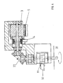
- FIG. 4 shows the generation of the rotation of a payload in the storage position by 360/720 °.
- the rotation of the coupling arrangement with chain wheel released by the cam-controlled spring band coupling is transmitted to the payload via an angular gear 22 and a second spring band coupling 31. After a rotation of max.
- the second spring band coupling 31 switches off the rotary movement of the payload 360 °.
- the angle of rotation can be increased by using a drag stop 32.
- a practical application is, for example, turning a workpiece through 180 ° for coating on both sides in a painting line.
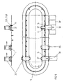
- a rotating transport system for supplying empty containers to a large mail distribution system (Fig. 5) transports a chain 5 over a locked coupling arrangement (Sprocket) a guided means of transport 1 with a container receptacle with corresponding Containers 35.
- an activated stop 14 releases the Locking function of the band spring and stops the container pick-up.
- the empty receptacle reaches the loading station 39.
- the Loading station 39 is the circulation of the Cross transport 37 completed, which supports the loading process and a possible required driver is brought back to the starting position.
- the traction means 5 moves at the speed V1, which is the coupling arrangement 3 blocked.
- a parallel traction device 40 runs at the speed V2, and a further coupling arrangement 41 coupled with this traction means 40 rotates.
- Runs in Switch cam 9 at the beginning of line 43 on a drag stop 44 begins to rotate the coupling element 3.
- a parallel one, with the towing fence 44 coupled stop 45 stops the rotation of the via a blocking device 42 Coupling arrangement 41, whereby the carrier 1 continues to run at the speed V2.
- the Rotation of the coupling arrangement 3 is proportional to the difference in Switzerlandstoffmaschineen.
- the towing stop 44 gives the Switching cam 9 again free, whereby the coupling arrangement 3 is blocked.
- the carrier 1 moves at the speed V1, because parallel to the blocking of the Coupling arrangement 3, the second coupling arrangement 41 via the drag stop 45 is disengaged.
Landscapes
- Engineering & Computer Science (AREA)
- Mechanical Engineering (AREA)
- Intermediate Stations On Conveyors (AREA)
- Discharge Of Articles From Conveyors (AREA)
- Attitude Control For Articles On Conveyors (AREA)
Description
Ein Nachteil der bekannten Lösungen besteht darin, daß das Ein- und Ausschleusen der Güter in die Behälter und sonstige Bewegungen der Güter bzw. Behälter, wie Dreh- und Schwenkbewegungen nur mit Hilfe aufwendiger separater Antriebe realisiert werden kann.
- Fig. 1
- eine Prinzipdarstellung der erfindungsgemäßen Vorrichtung mit der Kombination Zahnriemen - Zahnrad - Federbandkupplung - freie Nabe rotierend
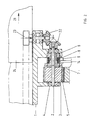
- Fig. 2
- eine Prinzipdarstellung mit der festen Nabe rotierend zur Erzeugung einer zusätzlichen Antriebsbewegung
- Fig. 3
- eine Prinzipdarstellung für den Einsatz der erfindungsgemäßen Vorrichtung zur Großbriefverteilung
- Fig. 4
- eine Prinzipdarstellung für die Erzeugung einer zusätzlichen Drehbewegung (360°/770°)
- Fig. 5
- eine Prinzipdarstellung für den Einsatz in einer Leerbehälterversorgungsanlage einer Großbriefverteilanlage
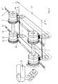
- Fig. 6
- eine Prinzipdarstellung mit zwei endlosen Zahnriemen/Ketten, zur Erzeugung einer Zusatzbewegung, während einer definierten Transportstrecke.
Die Zahnscheibe ist mit einem Zahnriemen 5 als Zugmittel im Eingriff und axial mit der freien Nabe 6 einer Federbandkupplung verbunden. Deren feste Nabe 7 ist starr am Träger befestigt.
Der identifizierte Brief wird in den Behälter 35 horizontal oder vertikal eingeschleust Technische Lösungen hierfür sind bekannt. Durch Deaktivierung des Anschlages in der Einschleuseposition 39 wird der Behälter weitertransportiert. Der mittransportierte Anschlag 12 löst sich von der aufgelaufenden Federbandkupplung, die selbsttätig sperrt, die Rotation stoppt und den Folgebehälter in die Einschleusposition bringt. Diesen kurzen Transportweg vollziehen alle gespeicherten Behälter nacheinander.
Die von der nockengesteuerten Federbandkupplung freigegebene Rotation der Kuppelanordnung mit Kettenrad wird über ein Winkelgetriebe 22 und eine zweite Federbandkupplung 31 auf die Nutzlast übertragen. Nach einer Drehbewegung von max. 360° schaltet die zweite Federbandkupplung 31 die Drehbewegung der Nutzlast ab. Durch Einsatz eines Schleppanschlages 32 läßt sich der Drehwinkel vergrößem. Eine praktische Anwendung ist z.B. das Drehen eines Werkstückes um 180° zum beidseitigen Beschichten in einer Lackierstraße.
Claims (7)
- Vorrichtung zum Transport, Speichern und Verteilen von Gütern unter Verwendung eines endlosen, ständig über Umlenkrollen umlaufenden Zugmittels (5), von geführten Transportmitteln (1, 13) mit jeweils einem Behälter, einer Koppelanordnung (3), die eine rotierende Bewegung ausführen kann und sich mit dem Zugmittel (5) ständig im Eingriff befindet, und einer Blockiervorrichtung (6 bis 9), die nur während ihrer Betätigung durch örtlich feste, in die Transportbahn der Transportmittel (1, 13) gesteuert eingreifende, sowie durch an den Transportmitteln (1, 13) befindliche Anschläge (12) die rotierende Bewegung der Koppelanordnung (3) freigibt und somit das Transportmittel (1, 13) vom Zugmittel (5) abkoppelt,
dadurch gekennzeichnet, daß die vom Zugmittel (5) hervorgerufenen rotierenden Bewegungen der Koppelanordnung (3) zum Antrieb von Kipp-, Schwenk- oder Drehanordnungen für die Behälter oder Güterein- und/oder Ausschleusanordnungen genutzt wird. - Vorrichtung nach Anspruch 1,
dadurch gekennzeichnet, daß neben dem Zugmittel (5) ein weiteres endloses, über Umlenkrollen geführtes bandförmiges Zugmittel (40) angeordnet ist, dessen Geschwindigkeit steuerbar ist, daß jedes Transportmittel über eine zweite Koppelanordnung (40), die eine rotierende Bewegung ausführen kann und zweite Blockiervorrichtung (42) mit diesem weiteren Zugmittel (40) im Eingriff steht, und daß die auf der Grundlage der Differenzgeschwindigkeit zwischen beiden endlosen Zugmitteln (5, 40) hervorgerufene rotierende Bewegung der ersten Koppelanordnung (3) zum Antrieb von Kipp-, Schwenk- oder Drehanordnungen für die Behälter oder Güterein- und/oder Auschleusanordnungen während des Transports der Transportmittel genutzt wird. - Vorrichtung nach Anspruch 1,
dadurch gekennzeichnet, daß die Koppelanordnung (3) ein gelagertes und mit dem Zugmittel kraft- oder formschlüssig gekoppeltes Rad ist. - Vorrichtung nach Anspruch 1,
dadurch gekennzeichnet, daß die Koppelanordnung Räder aufweist, auf denen mit dem Zugmittel kraft- oder formschlüssig im Eingriff befindliche endlose Koppelelemente laufen. - Vorrichtung nach Anspruch 1,
dadurch gekennzeichnet, daß die Blockiervorrichtung eine Federbandkupplung (8) ist. - Vorrichtung nach Anspruch 1,
dadurch gekennzeichnet, daß die Blockiervorrichtung durch einen Freilauf realisiert ist. - Vorrichtung nach Anspruch 1,
dadurch gekennzeichnet, daß die Blockiervorrichtung durch einen Exzenter oder eine Sperrklinke realisiert ist.
Applications Claiming Priority (2)
| Application Number | Priority Date | Filing Date | Title |
|---|---|---|---|
| DE19633096 | 1996-08-16 | ||
| DE19633096A DE19633096C1 (de) | 1996-08-16 | 1996-08-16 | Vorrichtung zum Transport, Speichern und Verteilen von Gütern |
Publications (2)
| Publication Number | Publication Date |
|---|---|
| EP0825136A1 EP0825136A1 (de) | 1998-02-25 |
| EP0825136B1 true EP0825136B1 (de) | 2003-04-16 |
Family
ID=7802823
Family Applications (1)
| Application Number | Title | Priority Date | Filing Date |
|---|---|---|---|
| EP97114074A Expired - Lifetime EP0825136B1 (de) | 1996-08-16 | 1997-08-14 | Vorrichtung zum Transport, Speichern und Verteilen von Gütern |
Country Status (2)
| Country | Link |
|---|---|
| EP (1) | EP0825136B1 (de) |
| DE (2) | DE19633096C1 (de) |
Families Citing this family (2)
| Publication number | Priority date | Publication date | Assignee | Title |
|---|---|---|---|---|
| DE102004006719B3 (de) * | 2004-02-11 | 2005-08-11 | WBS Fördertechnik GmbH | Vertikale Staufördervorrichtung |
| DE102004019922A1 (de) | 2004-04-21 | 2004-11-18 | Bär, Ralf, Dipl.-Ing. | Fördersystem für Werkstücke oder Gegenstände |
Family Cites Families (12)
| Publication number | Priority date | Publication date | Assignee | Title |
|---|---|---|---|---|
| GB601719A (en) * | 1946-06-04 | 1948-05-11 | King Ltd Geo W | Improvements in or relating to conveyor systems |
| USRE25886E (en) * | 1961-02-27 | 1965-10-26 | Manufacturing system using free floating fixture line | |
| BE639931A (de) * | 1963-01-14 | |||
| DE1256153B (de) * | 1966-07-27 | 1967-12-07 | Siemens Ag | Foerderanlage, insbesondere Kastenfoerderanlage, zur Befoerderung von Foerderbehaeltern in Fahrrinnen |
| FR2360485A1 (fr) * | 1976-08-06 | 1978-03-03 | Telecommunications Sa | Perfectionnements aux automates |
| DE3225595C2 (de) * | 1982-07-08 | 1986-01-30 | Bosch-Siemens Hausgeräte GmbH, 7000 Stuttgart | Transportbahn |
| DK174001B1 (da) * | 1987-11-13 | 2002-04-08 | Vortex Systems Srl | Apparat til transport og gruppering af emner |
| DE3836952C2 (de) * | 1988-10-29 | 1995-04-27 | Matthias Malatitsch | Palettenförderer |
| DE3926755A1 (de) * | 1989-08-12 | 1991-02-14 | Lanco Ag | Foerderanlage fuer werkstuecktraeger u. dergl. |
| DE4131068C2 (de) * | 1991-09-18 | 1994-05-05 | Beierling Annette | Vorrichtung zur Förderung und Drehung von Werkstücken |
| FR2719832B1 (fr) * | 1994-05-11 | 1996-08-02 | Mach Speciales Manutention | Plateau pour transporteur de type magasin à accumulation. |
| DE9416115U1 (de) * | 1994-10-06 | 1995-08-03 | F+S Automationstechnik GmbH, 74229 Oedheim | Paletten-Stauförderer |
-
1996
- 1996-08-16 DE DE19633096A patent/DE19633096C1/de not_active Expired - Fee Related
-
1997
- 1997-08-14 DE DE59709825T patent/DE59709825D1/de not_active Expired - Lifetime
- 1997-08-14 EP EP97114074A patent/EP0825136B1/de not_active Expired - Lifetime
Also Published As
| Publication number | Publication date |
|---|---|
| DE59709825D1 (de) | 2003-05-22 |
| EP0825136A1 (de) | 1998-02-25 |
| DE19633096C1 (de) | 1998-02-26 |
Similar Documents
| Publication | Publication Date | Title |
|---|---|---|
| EP2032481B1 (de) | Transporteur | |
| EP0930248B1 (de) | Vorrichtung zum Sortieren von Stückgütern | |
| DE4209115B4 (de) | System und Verfahren zum Befördern von Werkstücken | |
| DE4125573A1 (de) | Vorrichtung zum ein- oder auspacken von behaeltern | |
| DE10020608A1 (de) | Lager- und/oder Transportvorrichtung für Stückgüter | |
| DE102007040859A1 (de) | Querbandsorter und Verfahren zum Transportieren und Sortieren von Stückgut | |
| EP0249839B1 (de) | Seilförderanlage, insbesondere Seilschwebebahn | |
| EP1640294A2 (de) | Vorrichtung zum Ein- und Ausschleusen von Ladungsträgern oder Stückgütern | |
| EP0825136B1 (de) | Vorrichtung zum Transport, Speichern und Verteilen von Gütern | |
| EP2989030B1 (de) | Fördervorrichtung zum fördern von werkstücken, werkstückbehandlungsanlage und verfahren zum fördern von werkstücken | |
| DE4216721A1 (de) | Verfahren und Vorrichtung zum Ein- oder Auspacken von Artikeln in Gebinde oder aus Gebinden | |
| DE2429104A1 (de) | Huelsenlader | |
| DE8135650U1 (de) | "pufferkettenfoerderer" | |
| DE4119407C2 (de) | Behandlungsmaschine für Behälter, insbesondere Flaschen | |
| DE1275463C2 (de) | Vorrichtung zum periodischen Zufuehren von Behaeltern, z. B. Flaschen, an sich fortbewegende Traeger | |
| EP0912398B1 (de) | Verfahren und vorrichtung zum transportieren und gruppieren von scheibenförmigen produkten, insbesondere biskuits | |
| DE4131068C2 (de) | Vorrichtung zur Förderung und Drehung von Werkstücken | |
| DE1936371A1 (de) | Vorrichtung zur Abfoerderung fertiger Stapel von Druckwerken vom Auslauf einer Druckwerkstapelvorrichtung | |
| EP0015415B1 (de) | Werkstücktransporteinrichtung | |
| EP0824492B1 (de) | Übergabevorrichtung | |
| DE60222660T2 (de) | Vorrichtung für individuelle höhensortierung von platten | |
| EP0756994B1 (de) | Packmaschine zum gruppenweisen Ein- oder Auspacken von Flaschen oder dergl. Behältern in bzw. aus Flaschenkästen oder dergl. Gebinde | |
| DE3611494C2 (de) | ||
| DD143055A1 (de) | Kreisfoerderer mit radialen armen | |
| DE1117474B (de) | Verfahren und Vorrichtung zum Bewegen der Verteilerscheibe und der Transportscheibe bei Verpackungsmaschinen fuer Bonbons u. dgl. |
Legal Events
| Date | Code | Title | Description |
|---|---|---|---|
| PUAI | Public reference made under article 153(3) epc to a published international application that has entered the european phase |
Free format text: ORIGINAL CODE: 0009012 |
|
| AK | Designated contracting states |
Kind code of ref document: A1 Designated state(s): BE CH DE FR IT LI |
|
| AX | Request for extension of the european patent |
Free format text: AL;LT;LV;RO;SI |
|
| 17P | Request for examination filed |
Effective date: 19980505 |
|
| AKX | Designation fees paid |
Free format text: BE CH DE FR IT LI |
|
| RBV | Designated contracting states (corrected) |
Designated state(s): BE CH DE FR IT LI |
|
| GRAH | Despatch of communication of intention to grant a patent |
Free format text: ORIGINAL CODE: EPIDOS IGRA |
|
| GRAH | Despatch of communication of intention to grant a patent |
Free format text: ORIGINAL CODE: EPIDOS IGRA |
|
| GRAA | (expected) grant |
Free format text: ORIGINAL CODE: 0009210 |
|
| AK | Designated contracting states |
Designated state(s): BE CH DE FR IT LI |
|
| REG | Reference to a national code |
Ref country code: CH Ref legal event code: EP |
|
| REF | Corresponds to: |
Ref document number: 59709825 Country of ref document: DE Date of ref document: 20030522 Kind code of ref document: P |
|
| PG25 | Lapsed in a contracting state [announced via postgrant information from national office to epo] |
Ref country code: LI Free format text: LAPSE BECAUSE OF NON-PAYMENT OF DUE FEES Effective date: 20030831 Ref country code: CH Free format text: LAPSE BECAUSE OF NON-PAYMENT OF DUE FEES Effective date: 20030831 |
|
| ET | Fr: translation filed | ||
| PLBE | No opposition filed within time limit |
Free format text: ORIGINAL CODE: 0009261 |
|
| STAA | Information on the status of an ep patent application or granted ep patent |
Free format text: STATUS: NO OPPOSITION FILED WITHIN TIME LIMIT |
|
| 26N | No opposition filed |
Effective date: 20040119 |
|
| REG | Reference to a national code |
Ref country code: CH Ref legal event code: PL |
|
| PGFP | Annual fee paid to national office [announced via postgrant information from national office to epo] |
Ref country code: FR Payment date: 20090821 Year of fee payment: 13 |
|
| PGFP | Annual fee paid to national office [announced via postgrant information from national office to epo] |
Ref country code: DE Payment date: 20091019 Year of fee payment: 13 |
|
| PGFP | Annual fee paid to national office [announced via postgrant information from national office to epo] |
Ref country code: BE Payment date: 20090819 Year of fee payment: 13 |
|
| PGFP | Annual fee paid to national office [announced via postgrant information from national office to epo] |
Ref country code: IT Payment date: 20090826 Year of fee payment: 13 |
|
| BERE | Be: lapsed |
Owner name: *SIEMENS A.G. Effective date: 20100831 |
|
| REG | Reference to a national code |
Ref country code: FR Ref legal event code: ST Effective date: 20110502 |
|
| PG25 | Lapsed in a contracting state [announced via postgrant information from national office to epo] |
Ref country code: IT Free format text: LAPSE BECAUSE OF NON-PAYMENT OF DUE FEES Effective date: 20100814 |
|
| REG | Reference to a national code |
Ref country code: DE Ref legal event code: R119 Ref document number: 59709825 Country of ref document: DE Effective date: 20110301 |
|
| PG25 | Lapsed in a contracting state [announced via postgrant information from national office to epo] |
Ref country code: BE Free format text: LAPSE BECAUSE OF NON-PAYMENT OF DUE FEES Effective date: 20100831 Ref country code: FR Free format text: LAPSE BECAUSE OF NON-PAYMENT OF DUE FEES Effective date: 20100831 Ref country code: DE Free format text: LAPSE BECAUSE OF NON-PAYMENT OF DUE FEES Effective date: 20110301 |