EP0824008B1 - Essoreuse pour des bandes à franges ou serpillières - Google Patents
Essoreuse pour des bandes à franges ou serpillières Download PDFInfo
- Publication number
- EP0824008B1 EP0824008B1 EP97630047A EP97630047A EP0824008B1 EP 0824008 B1 EP0824008 B1 EP 0824008B1 EP 97630047 A EP97630047 A EP 97630047A EP 97630047 A EP97630047 A EP 97630047A EP 0824008 B1 EP0824008 B1 EP 0824008B1
- Authority
- EP
- European Patent Office
- Prior art keywords
- mop
- fringed
- wringer
- strips
- fact
- Prior art date
- Legal status (The legal status is an assumption and is not a legal conclusion. Google has not performed a legal analysis and makes no representation as to the accuracy of the status listed.)
- Expired - Lifetime
Links
- 238000009991 scouring Methods 0.000 title 1
- 239000007788 liquid Substances 0.000 claims description 17
- 238000003825 pressing Methods 0.000 claims description 7
- 238000009987 spinning Methods 0.000 description 13
- 210000002445 nipple Anatomy 0.000 description 5
- XLYOFNOQVPJJNP-UHFFFAOYSA-N water Substances O XLYOFNOQVPJJNP-UHFFFAOYSA-N 0.000 description 5
- 238000004140 cleaning Methods 0.000 description 4
- 238000003780 insertion Methods 0.000 description 4
- 230000037431 insertion Effects 0.000 description 4
- 230000003321 amplification Effects 0.000 description 2
- 230000015572 biosynthetic process Effects 0.000 description 2
- 230000006866 deterioration Effects 0.000 description 2
- 238000003199 nucleic acid amplification method Methods 0.000 description 2
- 239000002689 soil Substances 0.000 description 2
- 238000005406 washing Methods 0.000 description 2
- 241001644893 Entandrophragma utile Species 0.000 description 1
- 238000009825 accumulation Methods 0.000 description 1
- 239000000969 carrier Substances 0.000 description 1
- 230000006835 compression Effects 0.000 description 1
- 238000007906 compression Methods 0.000 description 1
- 238000010276 construction Methods 0.000 description 1
- 239000003599 detergent Substances 0.000 description 1
- 238000006073 displacement reaction Methods 0.000 description 1
- 238000001035 drying Methods 0.000 description 1
- 238000007654 immersion Methods 0.000 description 1
- 238000000034 method Methods 0.000 description 1
- 239000002245 particle Substances 0.000 description 1
- 230000003014 reinforcing effect Effects 0.000 description 1
- 238000000926 separation method Methods 0.000 description 1
- 238000002791 soaking Methods 0.000 description 1
- 238000003892 spreading Methods 0.000 description 1
- 238000009736 wetting Methods 0.000 description 1
Images


Classifications
-
- A—HUMAN NECESSITIES
- A47—FURNITURE; DOMESTIC ARTICLES OR APPLIANCES; COFFEE MILLS; SPICE MILLS; SUCTION CLEANERS IN GENERAL
- A47L—DOMESTIC WASHING OR CLEANING; SUCTION CLEANERS IN GENERAL
- A47L13/00—Implements for cleaning floors, carpets, furniture, walls, or wall coverings
- A47L13/10—Scrubbing; Scouring; Cleaning; Polishing
- A47L13/50—Auxiliary implements
- A47L13/58—Wringers for scouring pads, mops, or the like, combined with buckets
- A47L13/59—Wringers for scouring pads, mops, or the like, combined with buckets with movable squeezing members
Definitions
- the function of the bottom wall is generally to connect the two side walls and the front wall to provide sufficient structural strength to the wringer but it still meets an operational requirement.
- the bottom wall is a support plane and reception of the fringed or mop band to allow the spinning, in one action, the fringed band or mop, even if it has a longitudinal extension much greater than the height of the front wall.
- the bottom wall is perforated to allow, during the spinning fringe strips or mops, the outlet of the liquid they are impregnated.
- the rinse liquid is separated from the dirty liquid from the spin and the wringer is mounted on a two-bin bucket or mounted on a suitable container which collects the dirty wring water, a second container being available and containing clean water.
- a suitable container which collects the dirty wring water, a second container being available and containing clean water.
- the operator is forced, after plunging the fringed band or mop into the liquid for rinsing, to lift the fringed band or mop, barely soaked, with the structure that supports it, above the upper edge of the wringer to lower it down, by introducing it inside to perform the spin.
- the fringed band or mop that is introduced into these wringers can pass underneath, crossing them until it joins the underlying liquid and is immersed for the rinsing.
- the fringed or mop band is extracted from the liquid and lifted up to the useful height by remaining inside the wringer and then wrung out.
- the operator can thus quickly and easily rinse the fringed or mop band to rid it of the coarser particles of dirt in the liquid, and can then spin.
- the object of the invention is to solve all the aforementioned problems and disadvantages while at the same time improving the possibilities that could exist in prior spiners.
- the invention relates to a wringer which is provided with a movable pressing panel with parallel translational movement, acting against a flat bearing wall, and which has no bottom.
- the height of both the movable panel and the support wall is substantially equal to the entire extent of the fringed strips or mops to wring.
- the stroke of the control stick which is actuated by the operator, is reduced although it determines a wide translation of the movable pressing panel.
- the oscillating rotation of the handle determines the reciprocating rectilinear displacement of the movable panel by using kinematics with cranks and rods made according to principles known but appropriately dimensioned and located in a timely manner in the structure.
- the side walls have two guides of appropriate shape so that the mobile panel, at the end of its passive return stroke, tilts by enlarging the opening at the top to provide a entrance and a larger space for the insertion of the fringed band or mop.
- the nipples secured to the mobile wiper panel, which are applied to its blanks and which slide in the aforementioned guides, are in a parallel position set back from the previous active panel. That way, when the fringed band or mop is pushed, in front of the movable panel, against the front wall of support, the nipples do not intervene. This avoids, during the pressing phase, jamming due to the possible insertion of the threads of the fringed or mop band between the guides and the nipples, with consequent deterioration of the fringed band or mop itself .
- a first advantage of the wringer according to the present invention is due to the high uniformity of wringing of the surface of the fringed or mop band, substantially all of it, without accumulation in the lower part (as a result of absence of the bottom) and without the fringed or mop band being moved downward as happens with the roller wringers.
- a second advantage of the wringer according to the present invention is that it has, at the end of the return stroke of the mobile wiping panel, a wide mouth of entry for the band with fringes or mop which must be introduced and a light next satisfactory passage for the fringed band or mop that must pass through it to have access to the underlying container of the liquid for soaking and rinsing.
- a third advantage is due to the fact that the rinsing and subsequent wringing of the fringed or mop band take place during a single immersion and lifting operation and this, with great ease of introduction of the band with fringes or mop and another great ease of positioning and holding the fringed band or mop during spinning.
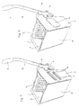
- Figure 1 shows the wringer according to the present invention viewed in perspective from one side and from above.
- This figure shows the centrifuge designated as a whole by the reference 1, the front end wall 2 provided with a multiplicity of holes, and the side walls 3 and 3 'connected at the rear by a cross member 16 ( not visible in Figure 1).
- the side walls 3 and 3 ' are formed the guide slots 4 and 4' in which the studs 12 integral with the movable panel 5 slide.
- the bearings 13 and 13' of a small shaft 8 which carries the levers 7 and 7 'to which are connected the rods 6 and 6' for controlling the movement of the movable panel 5.
- the shaft 8 is secured at one end, a hub 9 provided with a seat 14 in which is inserted a control sleeve 10 provided with a handle 11 for gripping on the part of the operator. If desired, it is possible to insert the handle 10 in seats which are provided with the lever arms 7 and 7 ', which allows to exclude, in such a case, the presence of the hub 9.
- the wringer is in the rest condition and the movable panel 5 is fully recessed so as to provide the maximum inlet opening for the insertion of the fringe tape. or mop. Note that in the wringer 1 the bottom is missing which gives a free passage through which can be made to pass the fringe or mop that must join the liquid in the underlying container.
- FIG. 2 differs from the preceding figure only in that a cap 15 is applied on the outside of the slots 4 for guiding the pins 12 of the movable panel 5.
- This cap 15 which can be easily removed, serves to prevent that, while spinning, water can be sprayed outside.
- the references assigned to the other parts have the same meaning as that previously adopted.
- FIG. 3 is a perspective view of the top of the wringer 1, taken from the rear, on which the movable panel 5 appears in the open position.
- This figure shows the lower crossmember 16 which connects the two side walls 3 and 3 ', the extensions 17 and 17' of the walls 3 and 3 ', which contribute to the formation of hook-shaped seats 18 for mounting the door. 1 on suitable carriers of a trolley or directly on the edge of suitable buckets.
- the front wall 2 and the slots 4 in which the studs 12 integral with the movable panel 5 slide.
- the bearings 13 and 13 'of the shaft 8 which carry the levers 7 and 7 ', the latter being connected to the connecting rods 6 and 6'.
- the hub 9 provided with the seat 14 inside which is inserted the handle 10 provided with the operating handle 11.
- FIG. 4 is a representation similar to that of FIG. 3 and it differs from the latter only as a result of the presence of the anti-projection cap 15 placed over the slots 4 for guiding the pins 12 of the movable panel 5. -projection 15 prevents the output of jets to from the slots 4 during the spin cycle.
- the references assigned to the other parts have the same meaning as that previously adopted.
- Figure 5 is a perspective view of the top of the wringer, taken from the front, on which the movable panel 5 is in an intermediate actuating position.
- the perforated front wall 2 provided with a series of reinforcing ribs 19.
- slots 20 and 20 ' provided for the insertion of the projections of a planar element which covers, at outside, almost completely the support wall, to prevent the release of any jets during the spin phase.
- FIG. 6 is a representation similar to that of FIG. 5 and it differs from this latter only by the addition of the anti-projection cap 15.
- the references which are assigned to the other parts have the same meaning as that previously adopted.
- Figure 7 shows the wringer seen in front lateral perspective taken from above.
- the movable panel 5 is in the maximum open position.
- the front wall 2 is provided with an anti-projection sheet 21 which is engaged by its two projections in the slots 20.
- Figure 8 is a representation similar to that of Figure 7 and differs from the latter only by the addition of the anti-projection cap 15.
- the references which are assigned to other parts, have the same meaning as previously adopted.
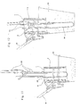
- Figure 9 shows the wringer 1 sectional view in a vertical and longitudinal plane, with the movable panel 5 being in the open position.
- This figure shows the perforated front wall 2 provided with the ribs 19, the side wall 3 extending through the extension 17 ensuring the formation of the hook-shaped seat 18.
- This figure also shows the guide slots 4 in FIG. which slide pins 12 secured to the movable panel 5. It may be noted that these nipples are in a position further back from the active spin panel, thus avoiding the jams that would occur during the spin if threads of the fringed band or mop came to engage in it.
- Figure 10 shows the wringer 1 in section along a vertical and longitudinal plane, the movable panel 5 is then in the maximum closed position. It should be noted that the movable panel 5 is completely leaning against the support wall 2, which allows to obtain a high uniformity of the spinning of the fringed band or mop.
- Figure 11 shows in section the wringer 1 mounted on the edge of a bucket 23 with an inserted fringe band 25.
- This figure shows the foldable articulated structure 24 supporting the fringed band 25 which is inserted inside the wringer in the space defined between the movable panel 5 and the support wall 2. In this position, the fringed band can be dewatered.
- Figure 12 shows in section the wringer 1 according to the present invention which is mounted on the edge of a bucket 23, being traversed by a fringed strip 25, and the relative support of the wringer.
- the fringed strip is immersed in the liquid of the bucket, the folding articulated structure 24 supporting it being insertable into the space defined between the movable panel 5 and the support wall 2.
- the absence of the bottom and the wide passage available between the support wall 2 and the movable panel 5 which is obtained with a normal stroke of the handle 10, constitutes as a whole the main innovative part of the wringer.
- Figure 13 and Figure 14 are representations corresponding to those of Figures 11 and 12, the support structure 24 and the associated fringe strip 25 being placed in profile and arranged flat.
- FIG. 15 and FIG. 16 are representations corresponding to those of FIGS. 11 and 12, the washing assembly previously consisting of the foldable articulated support 24 with the associated fringe band being replaced by a clamp support 26 with a fringed mop. associated 27.
Landscapes
- Cleaning Implements For Floors, Carpets, Furniture, Walls, And The Like (AREA)
- Treatment Of Fiber Materials (AREA)
- Cleaning In General (AREA)
Applications Claiming Priority (2)
| Application Number | Priority Date | Filing Date | Title |
|---|---|---|---|
| LU88802 | 1996-08-12 | ||
| LU88802A LU88802A1 (fr) | 1996-08-12 | 1996-08-12 | Essoreuse pour des bandes a franges ou serpilleres comprenant un panneau presseur a mouvement de translation parallele depourvue de fond pour permettre aux bandes a franges ou serpillieres de la traverser pour pouvoir etre plongee dans le liquide contenu dans un seau sous-adjacent |
Publications (3)
| Publication Number | Publication Date |
|---|---|
| EP0824008A2 EP0824008A2 (fr) | 1998-02-18 |
| EP0824008A3 EP0824008A3 (fr) | 1999-09-22 |
| EP0824008B1 true EP0824008B1 (fr) | 2008-01-02 |
Family
ID=19731618
Family Applications (1)
| Application Number | Title | Priority Date | Filing Date |
|---|---|---|---|
| EP97630047A Expired - Lifetime EP0824008B1 (fr) | 1996-08-12 | 1997-08-08 | Essoreuse pour des bandes à franges ou serpillières |
Country Status (9)
| Country | Link |
|---|---|
| EP (1) | EP0824008B1 (it) |
| AR (1) | AR006535A1 (it) |
| AT (1) | ATE382289T1 (it) |
| BR (1) | BR9703157A (it) |
| CA (1) | CA2215574C (it) |
| DE (1) | DE69738427D1 (it) |
| ES (1) | ES2297846T3 (it) |
| IT (1) | IT1294800B1 (it) |
| LU (1) | LU88802A1 (it) |
Cited By (1)
| Publication number | Priority date | Publication date | Assignee | Title |
|---|---|---|---|---|
| EP1937130A2 (en) | 2005-10-19 | 2008-07-02 | Unger Marketing International, LLC | Mop press having cam tracks |
Families Citing this family (17)
| Publication number | Priority date | Publication date | Assignee | Title |
|---|---|---|---|---|
| IL90188A0 (en) * | 1988-05-18 | 1989-12-15 | Cryopharm Corp | Process and medium for the lyophilization of erythrocytes |
| AU3156899A (en) * | 1998-04-03 | 1999-10-25 | Numatic International Limited | Mop press and mop press carrier |
| DE19827865C2 (de) | 1998-06-23 | 2001-06-21 | Gernot Hirse | Moppresse |
| GB9906023D0 (en) * | 1999-03-16 | 1999-05-12 | Jani Jack Ltd | Mop wringing devices |
| EP1185191B1 (en) | 1999-05-14 | 2006-12-13 | Numatic International Limited | Mop press |
| GB2352388B (en) * | 1999-07-26 | 2001-07-04 | Numatic Int Ltd | Improvements to mop presses |
| USD549414S1 (en) | 2005-01-31 | 2007-08-21 | Rubbermaid Commercial Products Llc | Mop frame |
| USD529294S1 (en) | 2005-01-31 | 2006-10-03 | Rubbermaid Commercial Products Llc | Universal joint |
| USD533356S1 (en) | 2005-01-31 | 2006-12-12 | Rubbermaid Commercial Products Llc | Universal joint |
| USD548913S1 (en) | 2005-05-10 | 2007-08-14 | Rubbermaid Commercial Products Llc | Mop bucket and wringer |
| USD528729S1 (en) | 2005-05-10 | 2006-09-19 | Rubbermaid Commerical Products Llc | Cart |
| USD547017S1 (en) | 2005-05-10 | 2007-07-17 | Rubbermaid Commercial Products Llc | Mop handle |
| WO2007136609A2 (en) * | 2006-05-16 | 2007-11-29 | Rubbermaid Commercial Products Llc | Mop bucket and wringer |
| USD549912S1 (en) | 2007-01-12 | 2007-08-28 | Rubbermaid Commercial Products Llc | Mop |
| US8938848B2 (en) * | 2009-10-30 | 2015-01-27 | Rubbermaid Commerical Products, Llc | Mop agitator |
| US9474429B2 (en) | 2013-03-15 | 2016-10-25 | Rubbermaid Commercial Products, Llc | Clean water mopping system |
| EP3288435B1 (en) | 2015-05-01 | 2022-04-13 | Ecolab USA Inc. | Mop bucket |
Family Cites Families (5)
| Publication number | Priority date | Publication date | Assignee | Title |
|---|---|---|---|---|
| US1954648A (en) * | 1931-12-31 | 1934-04-10 | George A Reitzel | Mop wringer |
| FR814316A (fr) * | 1936-09-19 | 1937-06-21 | Presse-balai | |
| US2651073A (en) * | 1947-09-25 | 1953-09-08 | Colson Corp | Mop wringer |
| DE8433865U1 (de) * | 1984-11-17 | 1985-02-14 | EWU AG, Rapperswil | Mop-flachpresse |
| DE3875742T2 (de) * | 1988-06-13 | 1993-06-09 | Dit International Hq A S | Mopwringer, mopwringsystem und eine walze. |
-
1996
- 1996-08-12 LU LU88802A patent/LU88802A1/fr unknown
-
1997
- 1997-04-04 AR ARP970101355A patent/AR006535A1/es not_active Application Discontinuation
- 1997-05-14 BR BR9703157A patent/BR9703157A/pt not_active IP Right Cessation
- 1997-07-30 IT IT97PD000174A patent/IT1294800B1/it active IP Right Grant
- 1997-08-08 AT AT97630047T patent/ATE382289T1/de not_active IP Right Cessation
- 1997-08-08 ES ES97630047T patent/ES2297846T3/es not_active Expired - Lifetime
- 1997-08-08 DE DE69738427T patent/DE69738427D1/de not_active Expired - Lifetime
- 1997-08-08 EP EP97630047A patent/EP0824008B1/fr not_active Expired - Lifetime
- 1997-08-12 CA CA002215574A patent/CA2215574C/fr not_active Expired - Fee Related
Cited By (1)
| Publication number | Priority date | Publication date | Assignee | Title |
|---|---|---|---|---|
| EP1937130A2 (en) | 2005-10-19 | 2008-07-02 | Unger Marketing International, LLC | Mop press having cam tracks |
Also Published As
| Publication number | Publication date |
|---|---|
| DE69738427D1 (de) | 2008-02-14 |
| LU88802A1 (fr) | 1997-02-13 |
| ATE382289T1 (de) | 2008-01-15 |
| IT1294800B1 (it) | 1999-04-15 |
| CA2215574C (fr) | 2004-03-02 |
| AR006535A1 (es) | 1999-09-08 |
| ITPD970174A1 (it) | 1999-01-30 |
| EP0824008A2 (fr) | 1998-02-18 |
| ES2297846T3 (es) | 2008-05-01 |
| EP0824008A3 (fr) | 1999-09-22 |
| CA2215574A1 (fr) | 1998-02-12 |
| BR9703157A (pt) | 1998-09-08 |
Similar Documents
| Publication | Publication Date | Title |
|---|---|---|
| EP0824008B1 (fr) | Essoreuse pour des bandes à franges ou serpillières | |
| EP1123683B1 (fr) | Dispositif d'ancrage du revêtement d'un balai de tissu sur son support associé | |
| FR2713912A1 (fr) | Dispositif pour collecter un liquide de lavage sale et contenir un liquide en vue d'imbiber une serpillière ou analogue pour laver à la main des sols ou similaires. | |
| FR2733141A1 (fr) | Ensemble a recipient et seau pour solution de nettoyage | |
| FR3010622A1 (fr) | Balai a tete basculante automatique pour nettoyage de surface | |
| EP0824336B1 (fr) | Outil d'assechement de surface et de recuperation simultanee de liquide | |
| FR2849364A1 (fr) | Dispositif de fixation pour fixer et detacher un receptable a poussiere d'un aspirateur de type cyclone et aspirateur comportant un tel dispositif | |
| FR2497629A1 (it) | ||
| EP2783619A1 (fr) | Combiné de lavage pour le nettoyage de sols ou autres surfaces planes | |
| FR2821735A1 (fr) | Lave-vaisselle et panier a couverts pour un tel lave-vaisselle | |
| FR2785785A1 (fr) | Distributeur de produits pour lave-vaisselle | |
| FR2490156A1 (fr) | Appareil pour le nettoyage, voire la conservation des instruments a appliquer la peinture | |
| FR2982757A1 (fr) | Combine de lavage pour le nettoyage de sols ou autres surfaces planes | |
| EP3937738B1 (fr) | Machine de preparation de boissons infusees munie d'un panier filtre relevable | |
| FR2997005A1 (fr) | Dispositif pour l'impregnation et l'essorage d'un ustensile de traitement de surface relie a un manche | |
| FR2817140A1 (fr) | Presse manuelle pour l'essorage de corps de nettoyage absorbants | |
| BE482699A (it) | ||
| FR3119305A1 (fr) | Outil d’asséchement et de récupération de liquide sur une surface, notamment vitrée. | |
| FR2665071A1 (fr) | Balai-brosse avec serpilliere a essorage integre. | |
| FR2701377A3 (fr) | Friteuse. | |
| BE425778A (it) | ||
| EP1369360A1 (fr) | Poubelle à tri sélectif | |
| BE385038A (it) | ||
| FR2737966A1 (fr) | Balai a serpilliere | |
| BE505756A (it) |
Legal Events
| Date | Code | Title | Description |
|---|---|---|---|
| PUAI | Public reference made under article 153(3) epc to a published international application that has entered the european phase |
Free format text: ORIGINAL CODE: 0009012 |
|
| AK | Designated contracting states |
Kind code of ref document: A2 Designated state(s): AT CH DE ES FR GB LI PT |
|
| AX | Request for extension of the european patent |
Free format text: AL;LT;LV;RO;SI PAYMENT 970822 |
|
| RAP1 | Party data changed (applicant data changed or rights of an application transferred) |
Owner name: A.Z. INTERNATIONAL S.A. |
|
| PUAL | Search report despatched |
Free format text: ORIGINAL CODE: 0009013 |
|
| AK | Designated contracting states |
Kind code of ref document: A3 Designated state(s): AT BE CH DE DK ES FI FR GB GR IE IT LI LU MC NL PT SE |
|
| AX | Request for extension of the european patent |
Free format text: AL;LT;LV;RO;SI PAYMENT 19970822 |
|
| 17P | Request for examination filed |
Effective date: 20000310 |
|
| AKX | Designation fees paid |
Free format text: AT CH DE ES FR GB LI PT |
|
| AXX | Extension fees paid |
Free format text: SI PAYMENT 19970822 |
|
| RAP1 | Party data changed (applicant data changed or rights of an application transferred) |
Owner name: L&M SERVICES B.V. |
|
| RAP1 | Party data changed (applicant data changed or rights of an application transferred) |
Owner name: FILMOP S.R.L. |
|
| GRAP | Despatch of communication of intention to grant a patent |
Free format text: ORIGINAL CODE: EPIDOSNIGR1 |
|
| GRAS | Grant fee paid |
Free format text: ORIGINAL CODE: EPIDOSNIGR3 |
|
| GRAA | (expected) grant |
Free format text: ORIGINAL CODE: 0009210 |
|
| AK | Designated contracting states |
Kind code of ref document: B1 Designated state(s): AT CH DE ES FR GB LI PT |
|
| AX | Request for extension of the european patent |
Extension state: SI |
|
| REG | Reference to a national code |
Ref country code: GB Ref legal event code: FG4D Free format text: NOT ENGLISH |
|
| REG | Reference to a national code |
Ref country code: CH Ref legal event code: EP |
|
| REF | Corresponds to: |
Ref document number: 69738427 Country of ref document: DE Date of ref document: 20080214 Kind code of ref document: P |
|
| REG | Reference to a national code |
Ref country code: ES Ref legal event code: FG2A Ref document number: 2297846 Country of ref document: ES Kind code of ref document: T3 |
|
| GBV | Gb: ep patent (uk) treated as always having been void in accordance with gb section 77(7)/1977 [no translation filed] | ||
| PG25 | Lapsed in a contracting state [announced via postgrant information from national office to epo] |
Ref country code: AT Free format text: LAPSE BECAUSE OF FAILURE TO SUBMIT A TRANSLATION OF THE DESCRIPTION OR TO PAY THE FEE WITHIN THE PRESCRIBED TIME-LIMIT Effective date: 20080102 |
|
| PG25 | Lapsed in a contracting state [announced via postgrant information from national office to epo] |
Ref country code: PT Free format text: LAPSE BECAUSE OF FAILURE TO SUBMIT A TRANSLATION OF THE DESCRIPTION OR TO PAY THE FEE WITHIN THE PRESCRIBED TIME-LIMIT Effective date: 20080602 |
|
| PLBE | No opposition filed within time limit |
Free format text: ORIGINAL CODE: 0009261 |
|
| STAA | Information on the status of an ep patent application or granted ep patent |
Free format text: STATUS: NO OPPOSITION FILED WITHIN TIME LIMIT |
|
| 26N | No opposition filed |
Effective date: 20081003 |
|
| PG25 | Lapsed in a contracting state [announced via postgrant information from national office to epo] |
Ref country code: GB Free format text: LAPSE BECAUSE OF FAILURE TO SUBMIT A TRANSLATION OF THE DESCRIPTION OR TO PAY THE FEE WITHIN THE PRESCRIBED TIME-LIMIT Effective date: 20080102 |
|
| PG25 | Lapsed in a contracting state [announced via postgrant information from national office to epo] |
Ref country code: DE Free format text: LAPSE BECAUSE OF FAILURE TO SUBMIT A TRANSLATION OF THE DESCRIPTION OR TO PAY THE FEE WITHIN THE PRESCRIBED TIME-LIMIT Effective date: 20080403 |
|
| PGFP | Annual fee paid to national office [announced via postgrant information from national office to epo] |
Ref country code: CH Payment date: 20110715 Year of fee payment: 15 |
|
| REG | Reference to a national code |
Ref country code: CH Ref legal event code: PL |
|
| PG25 | Lapsed in a contracting state [announced via postgrant information from national office to epo] |
Ref country code: CH Free format text: LAPSE BECAUSE OF NON-PAYMENT OF DUE FEES Effective date: 20130831 Ref country code: LI Free format text: LAPSE BECAUSE OF NON-PAYMENT OF DUE FEES Effective date: 20130831 |
|
| PGFP | Annual fee paid to national office [announced via postgrant information from national office to epo] |
Ref country code: FR Payment date: 20140723 Year of fee payment: 18 Ref country code: ES Payment date: 20140723 Year of fee payment: 18 |
|
| REG | Reference to a national code |
Ref country code: FR Ref legal event code: ST Effective date: 20160429 |
|
| PG25 | Lapsed in a contracting state [announced via postgrant information from national office to epo] |
Ref country code: FR Free format text: LAPSE BECAUSE OF NON-PAYMENT OF DUE FEES Effective date: 20150831 |
|
| REG | Reference to a national code |
Ref country code: ES Ref legal event code: FD2A Effective date: 20160926 |
|
| PG25 | Lapsed in a contracting state [announced via postgrant information from national office to epo] |
Ref country code: ES Free format text: LAPSE BECAUSE OF NON-PAYMENT OF DUE FEES Effective date: 20150809 |