EP0819198B1 - Selbstschwimmendes abschöpfgerät - Google Patents
Selbstschwimmendes abschöpfgerät Download PDFInfo
- Publication number
- EP0819198B1 EP0819198B1 EP96908017A EP96908017A EP0819198B1 EP 0819198 B1 EP0819198 B1 EP 0819198B1 EP 96908017 A EP96908017 A EP 96908017A EP 96908017 A EP96908017 A EP 96908017A EP 0819198 B1 EP0819198 B1 EP 0819198B1
- Authority
- EP
- European Patent Office
- Prior art keywords
- skimming
- floating
- floats
- skimming apparatus
- channel
- Prior art date
- Legal status (The legal status is an assumption and is not a legal conclusion. Google has not performed a legal analysis and makes no representation as to the accuracy of the status listed.)
- Expired - Lifetime
Links
- 238000007667 floating Methods 0.000 title claims abstract description 55
- 239000007788 liquid Substances 0.000 claims abstract description 68
- 238000007654 immersion Methods 0.000 claims description 30
- 230000007246 mechanism Effects 0.000 claims description 18
- 238000005259 measurement Methods 0.000 claims description 7
- 238000009966 trimming Methods 0.000 claims description 4
- 239000002131 composite material Substances 0.000 claims description 3
- 230000009182 swimming Effects 0.000 claims description 3
- 238000007599 discharging Methods 0.000 claims 3
- 238000010008 shearing Methods 0.000 claims 1
- 239000002344 surface layer Substances 0.000 abstract 1
- 241000238634 Libellulidae Species 0.000 description 84
- 230000000694 effects Effects 0.000 description 6
- 238000011161 development Methods 0.000 description 5
- 238000000034 method Methods 0.000 description 5
- 230000008569 process Effects 0.000 description 5
- 238000000926 separation method Methods 0.000 description 4
- 230000008878 coupling Effects 0.000 description 3
- 238000010168 coupling process Methods 0.000 description 3
- 238000005859 coupling reaction Methods 0.000 description 3
- 238000006073 displacement reaction Methods 0.000 description 3
- 238000011156 evaluation Methods 0.000 description 3
- 239000011324 bead Substances 0.000 description 2
- 230000008859 change Effects 0.000 description 2
- 238000005260 corrosion Methods 0.000 description 2
- 230000007797 corrosion Effects 0.000 description 2
- 238000013461 design Methods 0.000 description 2
- 238000004146 energy storage Methods 0.000 description 2
- 238000004064 recycling Methods 0.000 description 2
- 230000009467 reduction Effects 0.000 description 2
- 238000007789 sealing Methods 0.000 description 2
- 239000007787 solid Substances 0.000 description 2
- RZVAJINKPMORJF-UHFFFAOYSA-N Acetaminophen Chemical compound CC(=O)NC1=CC=C(O)C=C1 RZVAJINKPMORJF-UHFFFAOYSA-N 0.000 description 1
- 239000000654 additive Substances 0.000 description 1
- 239000000853 adhesive Substances 0.000 description 1
- 230000001070 adhesive effect Effects 0.000 description 1
- 230000002411 adverse Effects 0.000 description 1
- 230000008901 benefit Effects 0.000 description 1
- 150000001875 compounds Chemical class 0.000 description 1
- 238000011109 contamination Methods 0.000 description 1
- 230000009189 diving Effects 0.000 description 1
- 230000007613 environmental effect Effects 0.000 description 1
- 230000005484 gravity Effects 0.000 description 1
- 239000012535 impurity Substances 0.000 description 1
- 230000003993 interaction Effects 0.000 description 1
- 238000004519 manufacturing process Methods 0.000 description 1
- 239000000463 material Substances 0.000 description 1
- 239000000203 mixture Substances 0.000 description 1
- 230000000717 retained effect Effects 0.000 description 1
- 230000007704 transition Effects 0.000 description 1
- 230000000007 visual effect Effects 0.000 description 1
- 239000003643 water by type Substances 0.000 description 1
Images


Classifications
-
- E—FIXED CONSTRUCTIONS
- E02—HYDRAULIC ENGINEERING; FOUNDATIONS; SOIL SHIFTING
- E02B—HYDRAULIC ENGINEERING
- E02B15/00—Cleaning or keeping clear the surface of open water; Apparatus therefor
- E02B15/04—Devices for cleaning or keeping clear the surface of open water from oil or like floating materials by separating or removing these materials
- E02B15/10—Devices for removing the material from the surface
- E02B15/106—Overflow skimmers with suction heads; suction heads
Definitions
- the invention relates to a self-floating Skimmer for picking up the top layer of a liquid medium, with a drain for removal of the recorded medium and with one in a limited Angle around an axis between two fixed to each other spaced skimmers swiveling skimmer, the one receiving the skimmed-off medium Channel with an assigned inlet edge has, which acting on the skimming pan Buoyancy of the liquid medium compared to the Attacking edge and attacks behind the axis.
- Such a skimmer is from GB-A-1553-758 known. Also known as a skimmer Known skimmer, which has a central tube, into the liquid above the pipe flows in. The tube is surrounded by a flange in which it is held by clamping screws. To the Flanges are still connected by struts Swimmer. To stabilize the safe At least three swimmers are required for swimming. If the clamping screws are not tightened correctly or the pipe detaches from the corrosion Flange and sinks. This will in depth existing liquid removed and not on surface floating medium. You can also solids deposited on the floor become, causing pollution of the entire device or even to destroy device parts leads. The receiving cross section is only the cross section of the pipe.
- the invention is based on the object self-floating skimmer of the aforementioned Kind of creating the immersion depth the leading edge according to the type of medium to be picked up is adjustable, while overturning the skimming pan is prevented.
- this object is achieved by that one attached to the skimmer, adjustable plunge stop plunging and an exchange stop the replacement of the skimming pan limited, with both the plunge stop as also the exchange stop with a swimmer connecting connecting cross member and / or the Floats interacts.
- the immersion depth of the Leading edge to the type of liquid to be absorbed Medium are adjusted.
- the rollover continues prevents the skimming pan, which only properly run in liquid medium. Due to the adjustability of the immersion stop and the exchange stop does not have to each liquid medium to be skimmed is a separate one Skimmer or a separate skimmer pan provided become. So the skimmer is for Media of different consistency can be used.
- an off the gutter over the axis Inlet plate extending to the inlet edge intended.
- Through the from the gutter to the leading edge running inlet plate is an even one Guaranteed inflow of the liquid medium, wherein through a sloping slope from the leading edge to the gutter Inlet sheet strengthens the suction effect and so that a faster inflow is favored.
- the skimmer is designed for different skimming angles be applicable. No one is allowed to do this Fall liquid from a different side than that Feed the inlet edge into the gutter. Conveniently therefore end approximately, facing away from the axis outer wall of the channel running parallel to it and the gutter side walls above the level of the liquid medium, where one facing the axis and running parallel to it Inner wall of the gutter and that on the inner wall the inlet sheet that connects the gutter with the inlet edge in almost horizontal condition of the inlet plate below the level of the liquid medium lie.
- the elements interacting in the axis should be simple and expedient. To do this achieve, it is preferably provided that on the side walls the trough of the skimming pan bearing bushes are attached to the floats or to the Attached float-holding connecting cross beams The pivot pin engages the axis form.
- Such storage is easy to carry out and in the material pairing slightly to the liquid Medium customizable, increasing storage life is practically unlimited. Furthermore, the Length of the axis independent of the length of the skimming pan, which leads to a cost reduction.
- the skimmer So works according to the laws the physical buoyancy and displacement forces. As soon as the gutter of the skimming tank is empty, this floats up and turns the skimmer the axis. The full skimmer pan turns in the opposite direction the buoyancy around the axis, causing the Inlet edge above the level of the liquid medium protrudes. Through the resulting interplay between immersing and immersing the leading edge in the liquid medium is an unpowered mechanism guaranteed. This happens when immersed Filling the gutter. The filled gutter does that Dive out. After emptying the gutter the buoyancy forces plunge again and thus the filling. By this constellation one is certain functioning, no drive and therefore inexpensive Manufacture of the skimmer ensured.
- the plunge stop and / or the exchange stop or those interacting with it Elastic elements. This will the skimming pan is braked elastically with or without medium. Another advantage of this embodiment is noise reduction.
- the buoyancy force influences the filling volume of the Trough taken and therefore also on the rapid succession of Duty cycles.
- a Development of the invention on a skimmer arranged trim system adjustable buoyancy preferably consists of a cross to Axial trimmed weight recording and an adjustable Trim weight.
- trim weight is expedient attached to the immersion stop or to the immersion stop. This also results in the assembly of the one stop better handling as it works together with the trim weight is a large, easy-to-use part.
- the outflow of the Skimming pan at least one via a gutter hole on the Gutter attached drain hose. Through the downward connected and leading drain hose is therefore not further support of the process situation is required.
- the drain hose attached to the skimmer pan should also be used its weight does not have a great influence on the processes at Exercise immersion and immersion. Therefore, the gutter hole is convenient in the corner area between the inner wall and one Channel bottom of the channel provided. This allows the liquid Drain the medium completely out of the gutter.
- the Center of the gutter hole approximately in the middle in the corner area whereby from a semicircle from the bottom of the gutter and from the inner wall Rectangle is released, and a rectangular cut Pipe to which the drain hose is attached, the gutter hole covered.
- the Drainage of the skimming pan at least one immersed in the channel Suction pipe with a drain hose connected to it.
- the weight of the drain also affects this does not adversely affect the rotary movements of the skimming pan.
- the skimming pan is easy to seal. There are not any additional connection points available, about their attached elements of the drain hose to be attached ought to. So that the gutter can be emptied quickly, points the suction pipe prefers a large number over its circumference distribute pipe holes.
- the suction pipes immersed in the gutter and associated Drain hoses are to be held so that they function properly do not hinder. So the gutter with its inner wall, their outer wall and / or their side walls neither with the drain pipe, its holder or the drain hose in contact come. It is therefore expedient for the swimmers and / or the connecting crossbars connecting the floats a tube frame carrying the suction tubes is provided. To the Pipe frame is a simple holder of the necessary for the drain Elements possible. Access is possible at any time without being highlighted of the skimmer from the liquid possible.
- Closing and opening the gutter hole is also automatic feasible by rotating the skimming pan around its axis.
- the skimmer does not need any additional Units that monitor the position of the skimming pan and control the striking plate in the same way. Therefore, after a further development of the invention, the channel hole through the Strike plate locked when the leading edge is below the level of the liquid medium, and the striking plate releases the gutter hole when the skimmer pan turns around its axis tilts, and the leading edge from the level of the liquid Medium.
- the effects of physical Buoyancy and displacement forces acting on the skimming pan act, used twice.
- a rake is provided at the inlet edge of the skimming pan. Through the rake this is in the skimmer flowing medium already selected. This allows for example large impurities that affect the function would disturb, not flow.
- the computer has a closed top edge towards the top and has inflow openings spaced downward from the upper edge on.
- the invention is therefore on the float and / or the connecting crossbars at least one secondary float attached.
- the size of the secondary float is according to the one to be achieved Buoyancy is designed, which after removal of the secondary float dips the skimmer deeper and floats higher after adding.
- the float should be easy to carry out, and the secondary float should continue after loosening the skimmer remain local.
- the secondary float is therefore preferred attached at least one ring surrounding the float, wherein on the ring the position of the secondary swimmer towards the swimmer defining actuating means are arranged.
- the adjusting means arranged on the ring are preferred on the Circumference of the ring distributed screws with which the ring and thus the secondary float is attached to the float. No special tools are required for the adjustment, and the clamping force is distributed over the circumference of the float.
- the actuators immersed in the liquid are one exposed to increased corrosion. It is also cumbersome to operate the actuators below the liquid level. To also ensure a balance of the skimmer, is a simultaneous adjustment of the two secondary floats respectively.
- the actuating means is therefore preferred on the ring a truss stand on which an adjustment mechanism acts that adjusts both secondary floats.
- Actuators are preferably provided on the skimmer, which the adjustment mechanism, the striking plate and the Influence swivel limitation. This is largely automatic operation of the skimmer guaranteed.
- the actuator for the adjustment mechanism a cylinder acting on a scissors drive. Also for the use of all elements acting on the swivel movement is the use of inexpensive standardized components intended.
- the actuator is preferred for the swivel limitation a cylinder adjusting the trim weight and / or a drive controlling the swiveling movement of the skimming tank.
- a stepper motor can also be used for this Purpose builds small.
- Sensitive components must be protected from moisture and dirt to be protected.
- the actuators must be able to exercise required energy can be made available. To one great effort to protect these sensitive components avoid and to provide the energy in the vicinity of the actuator, is preferred in or on at least one of the Float an evaluation unit, an actuator and / or Energy storage provided.
- An unwanted swell is said to function as the skimmer do not unduly influence.
- the waves are said to be ahead the skimming pan are already weakened. Is achieved this in one embodiment of the invention by the Floats and / or secondary floats attached to the connecting crossbar, the at least partially in the longitudinal area reach into the skimmer. The acting waves are broken, and yet enough medium can be skimmed go directly to the skimming pan.
- skimming devices So that the skimmers don't get too big and still a large width can be blocked with skimmers, is expediently a composite system of several skimming devices combined into a skim chain. Here the merger also takes place by bringing them together the outflows in or above the liquid is feasible. By staggered one behind the other Uninterrupted protection is possible with skimming devices.
- a stationary use of installed, to a skim chain combined skimmers is advantageous there where liquid medium accumulates and is skimmed off must become.
- liquid medium accumulates and is skimmed off must become.
- the use in front of river weirs, behind industrial plants, in recycling plants, in which mixtures be separated into its components, and the like Systems conceivable.
- the liquid to be skimmed hits on a large one Surface, such as a lake or sea the skimmers connected to a skimming chain preferably integrated into a towing device.
- the skimmed Liquid is used by accompanying tankers added on which further separation of the liquid is carried out.
- the skimmer 3 floats freely in the container 1, the has a drain 4 which passes through the container wall 5.
- the drain 4 consists of a flexible drain hose 6, which is attached to pipe socket 8 with hose clips 7 is.
- the pipe socket 8 is sealed on the container side through the container bore 9. That from the container support 8 outflowing, skimmed medium is in one System not shown further processed.
- the pipe socket 8 on the side of the skimmer 3 has a quick coupling 10, via which the drain 4 is separated from the skimmer 3 becomes.
- the skimmer 3 has an elongated extension with a substantially rectangular skimmer 11.
- the Floats 12 are located on the narrow sides 13 of the skimming pan 11, being between the narrow sides 13 and Float 12 and float 12 and skimmer 11 connecting axis 14 is arranged.
- the skimmer 11 are arranged cross members 16, with which the float 12 are connected.
- the distance between the float 12 is chosen so that the skimming pan 11 can pivot freely about the axis 14.
- the connecting trusses 16 are round rods, each with a thread at their ends 17 wear with which they are screwed into threaded bushings 18 be welded to the floats 12.
- the skimming pan 11 consists essentially of three parts, two identical side walls 19 and a different axially parallel Bends 20 having center plate 21. On each the side walls 19 is out towards the float 12 each a bushing 22 welded. One each on Float 12 welded bearing pin 23 engages in the corresponding Bearing bush 22 and forms part of the axis 14. It is between the journal 23 and bearing bush 22 both Enough play in both radial and axial directions to prevent jamming when the movement of the Prevent skimmer 3.
- the side walls 19 of the skimming pan 11 form the shape of a lying on the side House.
- the middle plate 21 connected to the side walls 19 has approximately an L shape, the long leg 24 with the top edge 25 of the side walls 19 closes.
- the axis 14 is approximately horizontal centered on the side walls 19 and in the vertical direction arranged approximately in a ratio of 1: 1.5, the smaller one Part lies below.
- From the tip 26 of the side wall 19 extends compliant with the slope 27, an inlet plate 28, the a bend 20 forms a leading edge 29 and from there represents an inlet plate 30 running obliquely inwards downwards.
- the short leg 33 of the L-shape of the middle plate 21 represents the outer wall 31 of the skimmer 11, which is parallel to axis 14. Closer to axis 14, but still on the side of the outer wall 31, is the Inner wall 32, which is parallel to the axis 14 and to the outer wall 31 runs.
- the inner wall 32 and the outer wall 31 are opposite the long leg 24 between two bends 20 of the Middle plate 21 connected, this part of the channel bottom 34 represents a groove 35.
- the gutter settles 35 from the inner wall 32, corresponding to the height of the inner wall 32 Share the side walls 19 and the corresponding height the outer wall 31 together.
- This results in the skimming pan 11 is a one-sided cross-sectional shape opposite the leading edge 29 lying behind the axis 14 Channel 35 has. From the groove 35 extends to Leading edge 29 extending obliquely upwards over the axis 14 the inlet plate 30. Seen from above is the skimming pan 11 and thus the channel 35 closed all around.
- the skimmer 11 In a certain position, the skimmer 11 must be liquid Record medium. This position is shown in Fig. 4.
- the skimming pan 11 is in this case about the axis 14 Swiveled clockwise. This leads to the leading edge 29 to lie below the surface 2 of the liquid, and that medium to be recorded flows over the leading edge 29 and the like Inlet plate 30 in the empty channel 35.
- the inlet plate 30 has an almost horizontal alignment with a small one Inclination in the direction of the groove 35 in order to facilitate the inflow. In this position, the side walls 19 and the outer wall 31 over the surface 2 of the liquid.
- the skimming pan 11 In the position shown in FIG. 3, the skimming pan 11 is located skimmed liquid medium in the channel 35. As a result, the skimming pan 11 is counter to the axis 14 Swiveled clockwise, which next to those from the surface 2 of the liquid-looking side walls 19 and the outer wall 31 also the leading edge 29 above the surface 2 comes to rest. Liquid can no longer be skimmed off become. This is only after the skimmer has been emptied 11 possible again.
- the skimming pan 11 is empty (see FIG. 4), so is the buoyancy force 36 of the liquid acting thereon large that the skimming pan 11 about the axis 14 clockwise is rotated, and the medium to be skimmed over the Leading edge 29 into the skimming trough 11 or its trough 35 flows in. As the channel 35 fills, the buoyancy is sufficient 36 no longer out to the skimmer 11 in the to hold in the position shown in FIG. 4. It turns then counterclockwise to the position in Fig. 3.
- the displacement of the two stops 39, 40 is through the elongated holes 101 are limited in their in the guide insert, aligned parallel to the outer wall 31 wear and through which the screw 41 protrudes.
- On his the end facing the channel bottom 34 carries the exchange stop 39 a fold 43 and the immersion stop 40 a Bend 44.
- the bends 43, 44 are made so long that they extend into the area of the connecting cross member 16 and take them between them.
- the fold is there 44 of the immersion stop 40 below the connecting cross member 16 and the fold 43 of the exchange stop 39 above the connecting cross bar 16. If the distance between the folds 43, 44 changed, so also changes the angle through which the skimming pan 11 about the axis 14 pivots.
- the locking nut 42 is loosened and the immersion stop 40 down towards the channel bottom 34 moved, and after reaching the desired position the locking nut 42 tightened again.
- the fold 44 of the plunge stop 40 later on the connecting crossbar 16 to the system.
- the skimming pan 11 has covered a larger angle of rotation, and the leading edge 29 is immersed deeper. Analogously to this the rest of the adjustment is carried out.
- a trim system 46 is arranged above the skimming pan 11. It consists of a round bar 47 bent at right angles, an adjustment thread in the area above the skimming trough 11 49, which also the trim weight 50 is.
- a connector 48 bent at a right angle runs in Direction of the stops 39, 40 and is on the outside Exchange stop 39 arranged. So changes when adjusting the Austauchanschlag 39 also the trim system 46 its location what however in the position shown in Figs. 3 and 13 shows no effect. The one shown in FIG. 4 The center of gravity of the trimming system 46 changes slightly, which is generally negligible. Around To avoid this, the trimming system 46 can also be stationary, e.g. to be attached to the outer wall 31 of the skimmer 11.
- trim system 46 an influence on the buoyancy force 36 taken, i.e. it will affect the Exercised at the time of rotation of the skimming pan 11. Will that trim weight 51 located on the trim weight receptacle 50 shifted more to the right of the axis 14 in the direction of the leading edge 29, the skimmer tilts earlier clockwise until the immersion stop 40 comes into effect.
- the trim system 46 is transverse to axis 14 and is therefore less Adjusting the trim weight 51 has the greatest possible effect reached on the skimmer 11. Should the setting be more sensitive take place ', the trim system becomes oblique to the axis 14 arranged.
- a trough hole 52 In the trough 35 of the skimmer 11 there is a trough hole 52, to which the drain 4 with drain hose 6 is connected is.
- the channel hole 52 is in the corner area 54 between the inner wall 32 and the groove 35 delimiting the bottom Channel bottom 34 arranged.
- the center 53 of the gutter hole 52 is in the corner area 54.
- the alignment the axis of the channel hole 56 is perpendicular to the channel bottom 34.
- a semicircle is in the channel bottom 34 55 and a rectangle 56 is notched in the inner wall 32.
- With a rectangularly cut tube 57, which both the Semicircle 55 and rectangle 56 covers the gutter hole 52 tightly closed.
- One running all around The weld seam extends from the channel bottom 34 over the inner wall 32 to the inlet plate 30.
- On the pipe 57 is the quick coupling 10 attached, via which the drain 4 is connected.
- the suction pipes 59, 62 and 63 must have a certain fixed position Take 35 in the gutter. They are allowed to do the rotary movement the skimming pan 11 about the axis 14 do not hinder.
- a tubular frame 66 in the form of a bracket is attached to the Floats 12 attached. There are two holders on the tubular frame 66 67 attached, which surround the tube 68 of the tubular frame 66. The holders 67 run obliquely in the central region Direction of the trough 35 and there hold the suction pipe 59 or suction pipes 62 and 63.
- a rake 72 is attached above the inlet edge 29 of the skimmer 11 according to FIG. 10 .
- the Rake 72 In the lower area the Rake 72 a U-shape 73, which is between her legs engages around the end of the middle plate 21.
- the outside Leg is higher and has a leading edge 29 overlapping fold 74 with which the rake 72 over the Leading edge 29 is clipped.
- the rake plate 75 of the rake 72 runs parallel to the Edge of the side wall 19 runs.
- the width of the rake 72 is chosen so that it is exactly between the two side walls 19 of the skimmer 11 fits.
- the rake 72 according to FIG. 12 has a closed one Top edge 77. Spaced from top edge 77 inflow openings 78 are provided which are self-contained are and have the shape of a rectangle. In the immersion position can only medium through the inlet openings 78 flow, which is located at the level of the inflow openings 78.
- the floats 12 consist of a central pipe section 79, attached to the float cover 80 at both ends are.
- a bead 81 which is in the inner diameter 82 of the pipe section 79 is used and for a tight Connection provides.
- the float 12 becomes hermetic sealed.
- They are based on the same principle Secondary float 83 manufactured on the float 12th are attached. The attachment is done with two to the Pipe piece 79 of the float 12 circumferential rings 84. To the Rings 84 are attached to supports 85 which are connected to the secondary floats 83 are connected.
- adjusting means recessed as three that are offset by 120 ° to each other Screws 86 are formed.
- About the adjusting means is Secondary float 83 adjustable in height on float 12. If the skimmer 3 should float higher, then the secondary floats 83 are immersed deeper in the liquid, and this position is determined by means of the screws 86, which gives greater buoyancy to the whole Unity is exercised.
- the adjusting means in the arrangement according to FIGS. 15, 16 is a truss stand 87 attached to the rings 84.
- the middle part 88 of the truss stand 87 is rotatably mounted and via an adjusting rod 89 with an adjusting mechanism 90 connected.
- the adjustment mechanism 90 is one on one Cylinder 91 mounted scissors drive. Runs the push rod 99 of the cylinder 91, the outer nodes move 100 outward, and the secondary float 83 will pressed down, causing the skimmer 3 to float higher.
- the lowering takes place in the opposite direction. 15, 16 on the right Page by the adjustment mechanism 90 higher in weight is loaded, the secondary float 83 is on this side already set lower than on the opposite side. As a result, there is always a higher buoyancy available.
- Level sensors are on the float covers 80 of the floats 12 92 arranged with the skimmer 3 in the liquid immerse yourself. Via that determined by the level sensors 92 The result is the cylinder 91 of the adjustment mechanism 90 controlled accordingly and the optimal immersion depth set.
- a wave sensor detects the surface movement of the liquid Medium firmly in which the skimmer 3 floats.
- the wave sensor 17 is one of the coaxial on one Float 12 rotatably attached to the float axis 93 secondary float 83. The rotational movement is determined, converted and the measurement result for the corresponding adjustment mechanisms used.
- An evaluation unit is accommodated in the cavity 96 of the floats 12, which records the measurement results of the sensors and converted into control pulses for the actuators. Further is there is also the actuator (drive) for the swivel limitation the skimmer 11 housed. This is the bearing journal 23 inserted tightly into the float 12 and between the journal 23 and the bearing bush 22 is a forced driving arranged (not shown).
- the cavity is also suitable 96 best as an energy storage. It's filled with compressed air which are periodically reloaded via compressed air supply lines 96 becomes. Control lines go from the evaluation unit in the float 12 97 to cylinders 91 and 94 and the others Actuators.
- the secondary floats attached coaxially to the floats 12 83 extend with their longitudinal extent to the long sides 15 of the skimming pan 11. They thus serve also called a breakwater, causing the surface of the liquid Medium in front of the skimmer 11 is relatively quiet.
- the skimming devices 3 can be used in a variety of ways and are also of a size customizable. When several skimming devices are combined 3 to a skimming chain, the outflows are through a Compound system 98 summarized and transported away. In which The composite system 98 shown in FIG. 15 is the drain 4 held on the floats 12. The connection of the network system 98 takes place via corresponding couplings, e.g. Pipe swivel joints and quick connections. About this is the Skimming chain can be expanded as required. The skim chains are both stationary as well as behind a towing device Unit attached to ships can be used.
- the skimmers 3 are very versatile. So is in addition to the use in free waters also the use of smaller units in containers 1 conceivable.
- the various liquid media can be skimmed off. Next environmental protection is also used in recycling plants possible. Anywhere there is a medium in a liquid which floats at a certain height in the liquid is available, the skimmer 3 can be used.
- the medium to be skimmed can be liquid, doughy or also be firm. With a solid medium, the part of the Liquid that has been taken in for easy removal.
Landscapes
- Engineering & Computer Science (AREA)
- General Engineering & Computer Science (AREA)
- Environmental & Geological Engineering (AREA)
- Mechanical Engineering (AREA)
- Civil Engineering (AREA)
- Structural Engineering (AREA)
- Removal Of Floating Material (AREA)
- Catching Or Destruction (AREA)
- Agricultural Chemicals And Associated Chemicals (AREA)
- Crystals, And After-Treatments Of Crystals (AREA)
- Toys (AREA)
- Organic Low-Molecular-Weight Compounds And Preparation Thereof (AREA)
- Dry Shavers And Clippers (AREA)
- Non-Silver Salt Photosensitive Materials And Non-Silver Salt Photography (AREA)
- Level Indicators Using A Float (AREA)
Description
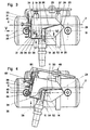
- Fig. 1
- einen Schnitt durch einen Behälter mit einem auf einer Flüssigkeit schwimmenden erfindungsgemäßen Abschöpfgerät,
- Fig. 2
- eine Draufsicht auf das Abschöpfgerät nach Fig. 1 in Pfeilrichtung II,
- Fig. 3
- einen Schnitt durch das Abschöpfgerät gemäß Fig. 1, in Richtung der Pfeile III-III, in vergrößerter Darstellung und in Ablauf Stellung,
- Fig. 4
- einen Schnitt gemäß Fig. 3 in Zulaufstellung,
- Fig. 5
- eine Darstellung der Einzelheit V gemäß Fig. 3,
- Fig. 6
- einen Teilschnitt durch Fig. 3 in Richtung der Pfeile VI-VI,
- Fig. 7
- einen Schnitt durch die Schwimmer gemäß Fig. 1 in Richtung der Pfeile VII-VII in vergrösserter Darstellung,
- Fig. 8
- einen Schnitt durch einen Behälter mit einem auf einer Flüssigkeit schwimmenden alternativen Abschöpfgerät nach der Erfindung,
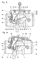
- Fig. 9
- einen Schnitt durch das Abschöpfgerät gemäß Fig. 8, in Richtung der Pfeile IX-IX, in vergrößerter Darstellung und in Ablaufstellung,
- Fig. 10
- einen Schnitt gemäß Fig. 9 mit verschiedenen alternativen Ausführungen,
- Fig. 11
- eine Ansicht auf die Einlaufkante gemäß Fig. 10 in Pfeilrichtung XI,
- Fig. 12
- eine alternative Ausführung der Einlaufkante nach Fig. 11,
- Fig. 13
- einen Schnitt durch eine alternative Ausführung eines Abschöpfgerätes in Ablaufstellung,
- Fig. 14
- einen Schnitt durch das Abschöpfgerät gemäß Fig. 13 in Zulaufstellung,
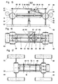
- Fig. 15
- eine Ansicht auf ein in einer Flüssigkeit schwimmendes Abschöpfgerät mit alternativen Zusätzen,
- Fig. 16
- eine Draufsicht auf das Abschöpfgerät gemäß Fig. 15 in Pfeilrichtung XVI und
- Fig. 17
- eine Draufsicht auf ein alternatives Abschöpfgerät.
Claims (38)
- Selbstschwimmendes Abschöpfgerät zur Aufnahme der Oberschicht eines flüssigen Mediums mit einem Abfluß (4) zum Abtransport des aufgenommenen Mediums und mit einer in einem begrenzten Winkel um eine Achse (14) zwischen zwei fest zueinander beabstandeten Schwimmern (12) schwenkbaren Abschöpfwanne (11), die eine das abgeschöpfte Medium aufnehmence Rinne (35) mit einer zugeordneten Einlaufkante (29 aufweist, wobei die auf die Abschöpfwanne (11) wirkende Auftriebskraft (36) des flüssigen Mediums gegenüber der Einlaufkante (29) und hinter der Achse (14) angreift, dadurch gekennzeichnet, daß ein jeweils an der Abschöpfwanne (11) befestigter, verstellbarer Eintauchanschlag (40) das Eintauchen und ein Austauchanschlag (39) das Austauchen der Abschöpfwanne (11) begrenzt, wobei sowohl der Eintauchanschlag (40) als auch der Austauchanschlag (39) mit einer die Schwimmer (12) verbindenden Verbindungstraverse (16) und/oder den Schwimmern (12) zusammenwirkt.
- Selbstschwimmendes Abschöpfgerät nach Anspruch 1, dadurch gekennzeichnet, daß die Abschöpfwanne (11) einseitig eine gegenüber einer Einlaufkante (29) hinter der Achse (14) liegende Rinne (35) für die Aufnahme des flüssigen Medius umfaßt, wobei ein von der Rinne (35) abgehendes, sich über die Achse (14) bis zur Einlaufkante (29) erstreckendes Zulaufblech (30) vorgesehen ist.
- Selbstschwimmendes Abschöpfgerät nach den Ansprüchen 1 und 2, dadurch gekennzeichnet, daß eine der Achse (14) abgewandte, parallel dazu verlaufende Außenwand (31) der Rinne (35) und die Rinne (35) seitlich abschließende Seitenwände (19) oberhalb des Niveaus des flüssigen Mediums enden, wobei eine der Achse (14) zugewandte, parallel dazu verlaufende Innenwand (32) der Rinne (35) und das sich an die Innenwand (32) anschließende Zulaufblech (30) mit der Einlaufkante (29) im annähernd waagrechten Zustand des Zulaufbleches (30) unterhalb des Niveaus des flüssigen Mediums liegen.
- Selbstschwimmendes Abschöpfgerät nach einem der Ansprüche 1 bis 3, dadurch gekennzeichnet, daß an den Seitenwänden (19) der Rinne (35) der Abschöpfwanne (11) Lagerbuchsen (22) befestigt sind, in die an den Schwimmern (12) oder an die Schwimmer (12) halternden Verbindungstraversen (16) angeordnete Lagerzapfen (23) drehbeweglich eingreifen, die die Achse (14) bilden.
- Selbstschwimmendes Abschöpfgerät nach einem der Ansprüche 1 bis 4, dadurch gekennzeichnet, daß die Auftriebskraft (36) des flüssigen Medims die leere Abschöpfwanne (11) um die Achse (14) dreht, wodurch die Einlaufkante (29) und das Zulaufblech (30) unter das Niveau des flüssigen Mediums tauchen.
- Selbstschwimmendes Abschöpfgerät nach einem der Ansprüche 1 bis 5, dadurch gekennzeichnet, daß die volle Abschöpfwanne (11) sich entgegen der Auftriebskraft (36) um die Achse (14) dreht, wodurch die Einlaufkante (29; über das Niveau des flüssigen Mediums hinausragt.
- Selbstschwimmendes Abschöpfgerät nach einem der Ansprüche 1 bis 6, dadurch gekennzeichnet, daß der Eintauchanschlag (40) und/oder der Austauchanschlag (39) oder die mit diesen zusammenwirkenden Elemente elastisch ausgeführt sind.
- Selbstschwimmendes Abschöpfgerät nach einem der Ansprüche 1 bis 7, dadurch gekennzeichnet, daß über ein an der Abschöpfwanne (11) angeordnetes Trimmsystem (46) die Auftriebskraft (36) einstellbar ist.
- Selbstschwimmendes Abschöpfgerät nach Anspruch 8, dadurch gekennzeichnet, daß das Trimmsystem (46) aus einer quer zur Achse (14) verlaufenden Trimmgewichtaufnahme (50) und einem daran verstellbaren Trimmgewicht (51) besteht.
- Selbstschwimmendes Abschöpfgerät nach Anspruch 9, dadurch gekennzeichnet, daß die Trimmgewichtaufnahme (50) am Eintauchanschlag (40) oder am Austauchanschlag (39) befestigt ist.
- Selbstschwimmendes Abschöpfgerät nach einem der Ansprüche 1 bis 10, dadurch gekennzeichnet, daß der Abfluß (4) der Abschöpfwanne (11) mindestens einen über ein Rinnenloch (52) an der Rinne (35) befestigten Ablaufschlauch (6) umfaßt.
- Selbstschwimmendes Abschöpfgerät nach Anspruch 11, dadurch gekennzeichnet, daß das Rinnenloch (52) im Eckbereich (54) zwischen der Innenwand (32) und einem Rinnenboden (34) der Rinne (35) vorgesehen ist.
- Selbstschwimmendes Abschöpfgerät nach den Ansprüchen 11 und 12, dadurch gekennzeichnet, daß das Zentrum (53) des Rinnenloches (52) sich etwa mittig im Eckbereich (54) befindet, wobei aus dem Rinnenboden (34) ein Halbkreis (55) und aus der Innenwand (32) ein Rechteck (56) ausgeklinkt ist, und ein rechteckig ausgeschnittenes Rohr (57), an dem der Ablaufschlauch (6) befestigt ist, das Rinnenloch (52) überdeckt.
- Selbstschwimmendes Abschöpfgerät nach einem der Ansprüche 1 bis 13, dadurch gekennzeichnet, daß der Abfluß (4) der Abschöpfwanne (11) mindestens ein in die Rinne (35) eingetauchtes Absaugrohr (59) mit einem daran angeschlosenen Ablaufschlauch (60) umfaßt.
- Selbstschwimmendes Abschöpfgerät nach Anspruch 14, dadurch gekennzeichnet, daß das Absaugrohr (59) eine Vielzahl von über seinen Umfang verteilten Rohrlöchern (61) aufweist.
- Selbstschwimmendes Abschöpfgerät nach Anspruch 14, dadurch gekennzeichnet, daß zwei an getrennte Ablaufschläuche (64, 65) angeschlossene Absaugrohre (62, 63) in die Rinne (35) eingetaucht sind, wobei bei einem Absaugrohr (63) die Rohrlöcher (61) zum Absaugen der oben schwimmenden Medien oberhalb der am anderen Absaugrohr (62) vorgesehenen Rohrlöcher (61) zum Absaugen der unten schwimmenden Medien angeordnet sind.
- Selbstschwimmendes Abschöpfgerät nach einem der Ansprüche 1 bis 16, dadurch gekennzeichnet, daß in der Rinne (35) und/oder dem Zulaufblech (30) Überlaufwehre und/oder Unterlaufwehre angebracht sind.
- Selbstschwimmendes Abschöpfgerät nach einem der Ansprüche 14 bis 17, dadurch gekennzeichnet, daß an den Schwimmern (12) und/oder den die Schwimmer (12) verbindenden Verbindungstraversen (16) ein die Absaugrohre (59, 62, 63) tragendes Rohrgestell (66) vorgesehen ist.
- Selbstschwimmendes Abschöpfgerät nach einem der Ansprüche 11 bis 19, dadurch gekennzeichnet, daß ein das Rinnenloch (52) verschließendes Schließblech (69) am Rohrgestell (66), den Schwimmern (12) oder den Verbindungstraversen (16) befestigt ist.
- Selbstschwimmendes Abschöpfgerät nach Anspruch 19, dadurch gekennzeichnet, daß das Rinnenloch (52) durch das Schließblech (69) verschlossen ist, wenn die Einlaufkante (29) unterhalb des Niveaus des flüssigen Mediums liegt, und daß das Schließblech (69) das Rinnenloch (52) freigibt, wenn die Abschöpfwanne (11) um ihre Achse (14) kippt, und die Einlaufkante (29) aus dem Niveau des flüssigen Mediums austaucht.
- Selbstschwimmendes Abschöpfgerät nach einem der Ansprüche 1 bis 20, dadurch gekennzeichnet, daß an der Einlaufkante (29) der Abschöpfwanne (11) ein Rechen (72) vorgesehen ist.
- Selbstschwimmendes Abschöpfgerät nach Anspruch 21, dadurch gekennzeichnet, daß der Rechen (72) noch oben hin offene Einströmöffnungen (76) aufweist
- Selbstschwimmendes Abschöpfgerät nach Anspruch 21, dadurch gekennzeichnet, daß der Rechen (72) nach oben hin eine geschlossene Oberkante (77) besitzt und von der Oberkante (77) nach unten beabstandet Einströmöffnungen (78) aufweist.
- Selbstschwimmendes Abschöpfgerät nach einem der Ansprüche 1 bis 23, dadurch gekennzeichnet, daß am Schwimmer (12) und/oder den Verbindungstraversen (16) mindestens ein Sekundärschwimmer (83) befestigt ist.
- Selbstschwimmendes Abschöpfgerät nach Anspruch 24, dadurch gekennzeichnet, daß der Sekundärschwimmer (83) höhenverstellbar am Schwimmer (12) und/oder den Verbindungstraversen (16) befestigt ist.
- Selbstschwimmendes Abschöpfgerät nach den Ansprüchen 24 und 25, dadurch gekennzeichnet, daß am Sekundärschwimmer (83) mindestens ein den Schwimmer (12) umgebender Ring (84) angebracht ist, wobei am Ring (84) die Stellung des Sekundärschwimmers (83) zum Schwimmer (12) festlegende Stellmittel angeordnet sind.
- Selbstschwimmendes Abschöpfgerät nach Anspruch 1 bis 26, dadurch gekennzeichnet, daß die am Ring (84) angeordneten Stellmittel auf dem Umfang des Ringes (84) verteilte Schrauben (86) sind, mit denen der Ring (84) und somit der Sekundärschwimmer (83) am Schwimmer (12) festgesetzt wird.
- Selbstschwimmendes Abschöpfgerät nach Anspruch 26, dadurch gekennzeichnet, daß das Stellmittel am Ring (84) ein Traversenständer (87) ist, auf den ein Verstellmechanismus (90) einwirkt, der beide Sekundärschwimmer (83) verstellt.
- Selbstschwimmendes Abschöpfgerät nach Anspruch 28, dadurch gekennzeichnet, daß an mindestens einem der Schwimmer (12) ein die Eintauchtiefe messender Niveausensor (92) angebracht ist, durch dessen Meßergebnis der Verstellmechanismus (90) die Lage der Sekundärschwimmer (83) einstellt.
- Selbstschwimmendes Abschöpfgerät nach Anspruch 28 oder 29, dadurch gekennzeichnet, daß ein Wellensensor die Oberflächenbewegungen des flüssigen Mediums feststellt, durch dessen Meßergebnis der Verstellmechanismus (90) die Lage der Sekundärschwimmer (83) einstellt, die Stellung des dem Rinnenloch (52) zugeordneten Schließbleches (69) beeinflußt und/oder den Winkel begrenzt, den die Abschöpfwanne (11) durchschwenkt.
- Selbstschwimmendes Abschöpfgerät nach einem der Ansprüche 19 bis 30, dadurch gekennzeichnet, daß Aktuatoren vorgesehen sind, die den Verstellmechanismus (90), das Schließblech (69) und die Schwenkbegrenzung beeinflußen.
- Selbstschwimmendes Abschöpfgerät nach Anspruch 31, dadurch gekennzeichnet, daß der Aktuator für den Verstellmechanismus (90) ein auf einen Scherentrieb wirkender Zylinder (91) ist.
- Selbstschwimmendes Abschöpfgerät nach Anspruch 31, dadurch gekennzeichnet, daß der Aktuator für die Schwenkbegrenzung ein das Trimmgewicht (51) verstellender Zylinder (94) und/oder ein die Schwenkbewegung der Abschöpfwanne (11) steuernder Antrieb ist.
- Selbstschwimmendes Abschöpfgerät nach einem der Ansprüche 1 bis 33, dadurch gekennzeichnet, daß in oder an mindestens einem der Schwimmer (12) eine Auswerteeinheit, ein Aktuator und/oder ein energiespendender Druckluftspeicher vorgesehen ist.
- Selbstschwimmendes Abschöpfgerät nach einem der Ansprüche 1 bis 34, dadurch gekennzeichnet, daß am Schwimmer (12) und/oder den Verbindungstraversen (16) Sekundärschwimmer (83) angebracht sind, die mindestens teilweise in den Längsbereich der Abschöpfwanne (11) hineinreichen.
- Selbstschwimmendes Abschöpfgerät nach einem der Ansprüche 1 bis 35, dadurch gekennzeichnet, daß ein Verbundsystem (98) mehrere Abschöpfgeräte zu einer Abschöpfkette zusammenschließt.
- Selbstschwimmendes Abschöpfgerät nach Anspruch 36, dadurch gekennzeichnet, daß die zu einer Abschöpfkette zusammengeschlossenen Abschöpfgeräte (3) stationär installiert sind.
- Selbstschwimmendes Abschöpfgerät nach Anspruch 36, dadurch gekennzeichnet, daß die zu einer Abschöpfkette zusammengeschlossenen Abschöpfgeräte (3) in eine Schleppvorrichtung integriert sind.
Applications Claiming Priority (3)
| Application Number | Priority Date | Filing Date | Title |
|---|---|---|---|
| DE19512279A DE19512279C2 (de) | 1995-04-01 | 1995-04-01 | Selbstschwimmendes schwenkendes Abschöpfgerät |
| DE19512279 | 1995-04-01 | ||
| PCT/DE1996/000606 WO1996031662A1 (de) | 1995-04-01 | 1996-03-27 | Selbstschwimmendes abschöpfgerät |
Publications (2)
| Publication Number | Publication Date |
|---|---|
| EP0819198A1 EP0819198A1 (de) | 1998-01-21 |
| EP0819198B1 true EP0819198B1 (de) | 2000-08-02 |
Family
ID=7758551
Family Applications (1)
| Application Number | Title | Priority Date | Filing Date |
|---|---|---|---|
| EP96908017A Expired - Lifetime EP0819198B1 (de) | 1995-04-01 | 1996-03-27 | Selbstschwimmendes abschöpfgerät |
Country Status (6)
| Country | Link |
|---|---|
| EP (1) | EP0819198B1 (de) |
| AT (1) | ATE195158T1 (de) |
| AU (1) | AU5142796A (de) |
| DE (2) | DE19512279C2 (de) |
| DK (1) | DK0819198T3 (de) |
| WO (1) | WO1996031662A1 (de) |
Cited By (1)
| Publication number | Priority date | Publication date | Assignee | Title |
|---|---|---|---|---|
| DE102020105262A1 (de) | 2020-02-28 | 2021-09-02 | Biogest International Gmbh | Klarwasser-Abzugseinrichtung (Dekanter) für eine Kläranlage |
Families Citing this family (9)
| Publication number | Priority date | Publication date | Assignee | Title |
|---|---|---|---|---|
| DE19713375A1 (de) * | 1996-04-17 | 1997-10-30 | Frembgen Fritz Herbert | Vorrichtung zum Absaugen der Oberflächenschicht einer Flüssigkeit |
| AU9652798A (en) * | 1997-10-13 | 1999-05-03 | Suparator B.V. | Device for continuously skimming off a floating toplayer |
| NO306248B1 (no) * | 1998-06-29 | 1999-10-11 | Norske Stats Oljeselskap | Röranordning for væskeutlöp fra en beholder, særlig en separasjonstank |
| DE10031160B4 (de) * | 2000-06-27 | 2010-01-14 | Meissner, Werner | Vorrichtung zum Entfernen von Verunreinigungen von der Oberfläche einer Flüssigkeit |
| ES2525682T3 (es) * | 2005-02-17 | 2014-12-29 | Suparator International B.V. | Aparato para desnatar continuamente una capa superior de un cuerpo de líquido |
| US8449768B2 (en) | 2010-10-07 | 2013-05-28 | National Response Corporation | Automatic tilting oil skimmer frame |
| DE102016101733A1 (de) * | 2016-02-01 | 2017-08-03 | Alfred Römhild | Vorrichtung zur Entfernung von Verunreinigungen aus Gewässern |
| RU171431U1 (ru) * | 2016-04-26 | 2017-05-31 | Научно-производственная фирма с ограниченной ответственностью "Экополимер" | Устройство сбора плавающих веществ |
| KR102223372B1 (ko) * | 2019-05-21 | 2021-03-05 | 서울대학교산학협력단 | 물-기름 분리 장치 |
Family Cites Families (8)
| Publication number | Priority date | Publication date | Assignee | Title |
|---|---|---|---|---|
| DE1282289B (de) * | 1958-08-25 | 1968-11-07 | Oscar Pauser | Geraet zum Entfernen von auf dem Wasser eines Schwimmbeckens oder auf einer aehnlichen Wasseransammlung schwimmendem Schmutz |
| FR2208697A1 (de) * | 1972-12-02 | 1974-06-28 | Erdol Raffinerie Noustadt Gmbh | |
| GB1391032A (en) * | 1973-01-25 | 1975-04-16 | Texaco Ltd | Liquid separator for surge pond and the like |
| US4010103A (en) * | 1974-08-12 | 1977-03-01 | Morgan Jerry E | Automatic oil-water separating device |
| GB1553758A (en) * | 1977-08-13 | 1979-09-26 | Lathe D C C | Skimming device |
| US4288324A (en) * | 1978-08-31 | 1981-09-08 | Urdanoff Howard D | Skimming apparatus |
| DE8632638U1 (de) * | 1986-12-05 | 1987-02-12 | Passavant-Werke AG, 6209 Aarbergen | Vorrichtung zum Abziehen von Schwimmstoffen |
| AU8749191A (en) * | 1990-10-29 | 1992-05-26 | Thomas Merlin Maddock | Apparatus and method for separating liquids of different relative densities |
-
1995
- 1995-04-01 DE DE19512279A patent/DE19512279C2/de not_active Expired - Fee Related
-
1996
- 1996-03-27 WO PCT/DE1996/000606 patent/WO1996031662A1/de not_active Ceased
- 1996-03-27 AT AT96908017T patent/ATE195158T1/de not_active IP Right Cessation
- 1996-03-27 EP EP96908017A patent/EP0819198B1/de not_active Expired - Lifetime
- 1996-03-27 AU AU51427/96A patent/AU5142796A/en not_active Abandoned
- 1996-03-27 DK DK96908017T patent/DK0819198T3/da active
- 1996-03-27 DE DE59605679T patent/DE59605679D1/de not_active Expired - Fee Related
Cited By (1)
| Publication number | Priority date | Publication date | Assignee | Title |
|---|---|---|---|---|
| DE102020105262A1 (de) | 2020-02-28 | 2021-09-02 | Biogest International Gmbh | Klarwasser-Abzugseinrichtung (Dekanter) für eine Kläranlage |
Also Published As
| Publication number | Publication date |
|---|---|
| DE19512279C2 (de) | 1997-09-11 |
| DE59605679D1 (de) | 2000-09-07 |
| AU5142796A (en) | 1996-10-23 |
| DE19512279A1 (de) | 1996-10-02 |
| DK0819198T3 (da) | 2000-11-13 |
| ATE195158T1 (de) | 2000-08-15 |
| WO1996031662A1 (de) | 1996-10-10 |
| EP0819198A1 (de) | 1998-01-21 |
Similar Documents
| Publication | Publication Date | Title |
|---|---|---|
| DE3234541C2 (de) | ||
| DE69633014T2 (de) | Konstruktion eines vakuumbehälters für eine vakuumtoilettenanordnung | |
| DE3026519C2 (de) | Einrichtung zur Regenerierung von verschlammten Gewässern | |
| EP0819198B1 (de) | Selbstschwimmendes abschöpfgerät | |
| DE2458192C3 (de) | Spülkasten für ein Wasserklosett | |
| DE2006659A1 (de) | Unterwassertank | |
| DE9013861U1 (de) | Tauchwand für Regen- und Klärbecken | |
| CH493707A (de) | Schwimmer | |
| DE69901362T2 (de) | Vorrichtung zur Aufbereitung von in Becken befindlichen Gewässern | |
| WO1991004087A1 (de) | Einrichtung zum absaugen von flüssigkeiten | |
| DE4302978C2 (de) | Schwimmende Filteranlage für Schwimmbecken | |
| EP0083358A1 (de) | Automatische einfüllvorrichtung für batteriezellen. | |
| DE2914007C3 (de) | Vorrichtung zum Trennen eines Gemisches von Flüssigkeiten verschiedener, spezifischer Gewichte, z.B. Öl und Wasser | |
| DE2406857C3 (de) | Vorrichtung für den Flüssigkeitsabzug aus Becken o.dgl., insbesondere Abwasserbecken | |
| DE2754472C2 (de) | Vorrichtung zum Abtrennen einer Flüssigkeit von einer anderen Flüssigkeit | |
| EP1287206B1 (de) | Vorrichtung zum bergen von öl eines ölteppichs auf einem gewässer | |
| CH617864A5 (en) | Apparatus for recovering oil | |
| DE2154934A1 (de) | Ventilanordnung an der Auslaßöffnung eines Flüssigkeitsbehälters | |
| DE1634156B2 (de) | Vorrichtung zum aufbringen einer schicht aus bituminoesem material auf den boden unter wasser | |
| EP2256575B1 (de) | Vorrichtung zum selbsttätigen Verschließen eines Zulaufes eines Behälters zur Aufnahme einer Flüssigkeit und Abscheidevorrichtung | |
| DE602004013432T2 (de) | Standregelung für flüssigkeitsdurchlauf | |
| DE10031160B4 (de) | Vorrichtung zum Entfernen von Verunreinigungen von der Oberfläche einer Flüssigkeit | |
| DE19618186C2 (de) | Abflußregelvorrichtung | |
| DE221873C (de) | ||
| DE2452574C3 (de) | Vorrichtung zum Belüften von Wasser |
Legal Events
| Date | Code | Title | Description |
|---|---|---|---|
| PUAI | Public reference made under article 153(3) epc to a published international application that has entered the european phase |
Free format text: ORIGINAL CODE: 0009012 |
|
| 17P | Request for examination filed |
Effective date: 19970925 |
|
| AK | Designated contracting states |
Kind code of ref document: A1 Designated state(s): AT CH DE DK FR GB IT LI NL |
|
| GRAG | Despatch of communication of intention to grant |
Free format text: ORIGINAL CODE: EPIDOS AGRA |
|
| 17Q | First examination report despatched |
Effective date: 19991018 |
|
| GRAG | Despatch of communication of intention to grant |
Free format text: ORIGINAL CODE: EPIDOS AGRA |
|
| GRAH | Despatch of communication of intention to grant a patent |
Free format text: ORIGINAL CODE: EPIDOS IGRA |
|
| GRAH | Despatch of communication of intention to grant a patent |
Free format text: ORIGINAL CODE: EPIDOS IGRA |
|
| GRAA | (expected) grant |
Free format text: ORIGINAL CODE: 0009210 |
|
| AK | Designated contracting states |
Kind code of ref document: B1 Designated state(s): AT CH DE DK FR GB IT LI NL |
|
| REF | Corresponds to: |
Ref document number: 195158 Country of ref document: AT Date of ref document: 20000815 Kind code of ref document: T |
|
| REG | Reference to a national code |
Ref country code: CH Ref legal event code: EP |
|
| REF | Corresponds to: |
Ref document number: 59605679 Country of ref document: DE Date of ref document: 20000907 |
|
| ITF | It: translation for a ep patent filed | ||
| REG | Reference to a national code |
Ref country code: CH Ref legal event code: NV Representative=s name: PA ALDO ROEMPLER |
|
| REG | Reference to a national code |
Ref country code: DK Ref legal event code: T3 |
|
| GBT | Gb: translation of ep patent filed (gb section 77(6)(a)/1977) |
Effective date: 20001027 |
|
| ET | Fr: translation filed | ||
| PLBE | No opposition filed within time limit |
Free format text: ORIGINAL CODE: 0009261 |
|
| STAA | Information on the status of an ep patent application or granted ep patent |
Free format text: STATUS: NO OPPOSITION FILED WITHIN TIME LIMIT |
|
| 26N | No opposition filed | ||
| REG | Reference to a national code |
Ref country code: GB Ref legal event code: IF02 |
|
| PGFP | Annual fee paid to national office [announced via postgrant information from national office to epo] |
Ref country code: GB Payment date: 20050322 Year of fee payment: 10 |
|
| PGFP | Annual fee paid to national office [announced via postgrant information from national office to epo] |
Ref country code: DK Payment date: 20050323 Year of fee payment: 10 |
|
| PG25 | Lapsed in a contracting state [announced via postgrant information from national office to epo] |
Ref country code: IT Free format text: LAPSE BECAUSE OF NON-PAYMENT OF DUE FEES;WARNING: LAPSES OF ITALIAN PATENTS WITH EFFECTIVE DATE BEFORE 2007 MAY HAVE OCCURRED AT ANY TIME BEFORE 2007. THE CORRECT EFFECTIVE DATE MAY BE DIFFERENT FROM THE ONE RECORDED. Effective date: 20050327 |
|
| PGFP | Annual fee paid to national office [announced via postgrant information from national office to epo] |
Ref country code: NL Payment date: 20050425 Year of fee payment: 10 |
|
| PG25 | Lapsed in a contracting state [announced via postgrant information from national office to epo] |
Ref country code: GB Free format text: LAPSE BECAUSE OF NON-PAYMENT OF DUE FEES Effective date: 20060327 |
|
| PG25 | Lapsed in a contracting state [announced via postgrant information from national office to epo] |
Ref country code: DK Free format text: LAPSE BECAUSE OF NON-PAYMENT OF DUE FEES Effective date: 20060331 |
|
| PGFP | Annual fee paid to national office [announced via postgrant information from national office to epo] |
Ref country code: FR Payment date: 20060331 Year of fee payment: 11 Ref country code: AT Payment date: 20060331 Year of fee payment: 11 |
|
| PGFP | Annual fee paid to national office [announced via postgrant information from national office to epo] |
Ref country code: CH Payment date: 20060425 Year of fee payment: 11 |
|
| PG25 | Lapsed in a contracting state [announced via postgrant information from national office to epo] |
Ref country code: NL Free format text: LAPSE BECAUSE OF NON-PAYMENT OF DUE FEES Effective date: 20061001 |
|
| REG | Reference to a national code |
Ref country code: DK Ref legal event code: EBP |
|
| GBPC | Gb: european patent ceased through non-payment of renewal fee |
Effective date: 20060327 |
|
| NLV4 | Nl: lapsed or anulled due to non-payment of the annual fee |
Effective date: 20061001 |
|
| REG | Reference to a national code |
Ref country code: CH Ref legal event code: PL |
|
| PG25 | Lapsed in a contracting state [announced via postgrant information from national office to epo] |
Ref country code: AT Free format text: LAPSE BECAUSE OF NON-PAYMENT OF DUE FEES Effective date: 20070327 |
|
| REG | Reference to a national code |
Ref country code: FR Ref legal event code: ST Effective date: 20071130 |
|
| PG25 | Lapsed in a contracting state [announced via postgrant information from national office to epo] |
Ref country code: LI Free format text: LAPSE BECAUSE OF NON-PAYMENT OF DUE FEES Effective date: 20070331 Ref country code: CH Free format text: LAPSE BECAUSE OF NON-PAYMENT OF DUE FEES Effective date: 20070331 |
|
| PG25 | Lapsed in a contracting state [announced via postgrant information from national office to epo] |
Ref country code: FR Free format text: LAPSE BECAUSE OF NON-PAYMENT OF DUE FEES Effective date: 20070402 |
|
| PGFP | Annual fee paid to national office [announced via postgrant information from national office to epo] |
Ref country code: DE Payment date: 20080523 Year of fee payment: 13 |
|
| PG25 | Lapsed in a contracting state [announced via postgrant information from national office to epo] |
Ref country code: DE Free format text: LAPSE BECAUSE OF NON-PAYMENT OF DUE FEES Effective date: 20091001 |